Table of Contents
Advertisement
Quick Links
Advertisement
Table of Contents

Related Manuals for Easy-Laser XT40


Summary of Contents for Easy-Laser XT40
- Page 1 User Manual English 05-0835 (EN) Revision 2.0 User Manual last built: 9/12/2017...
-
Page 3: Table Of Contents
DISPLAY UNIT XT11 Startscreen Info display on XT11 New, continue and save New or Continue session Save Finalize Finalize a measurement View a finalized measurement Create a template File manager Copy/Edit Filter Select filter Charge XT11 Camera IR camera Settings... - Page 4 Autorecord Calibration check Quick check Precision check HORIZONTAL Workflow Prepare Set up measuring units Rough align Enter distances Coupling diameter Tolerance Softfoot Thermal compensation Name the machine Measure using EasyTurn™ Measure using 9-12-3 Measure using Multipoint Measure using Continuous sweep Result Result table As found or As left...
- Page 5 Settings Align with targets Report TECHNICAL DATA Display unit XT11 Display unit Cables Brackets etc. Measuring units XT40 Laser classification Measuring units XT60 Laser classification XT440 Shaft A complete system contains Customize your XT11 XT660 Shaft A complete system contains...
- Page 6 This page intentionally left blank to ensure new chapters start on right (odd number) pages.
-
Page 7: Display Unit
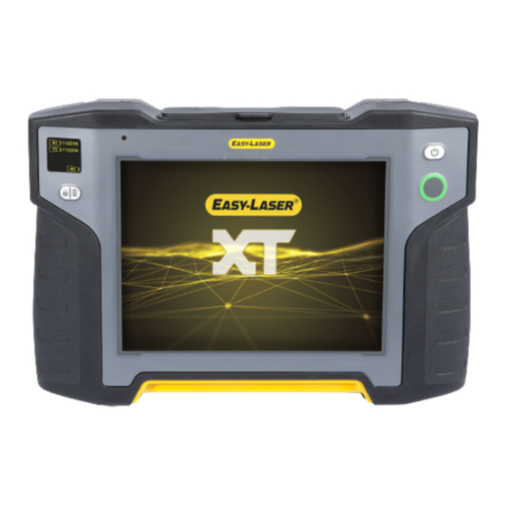
DISPLAY UNIT XT11 STARTSCREEN A. The info display show battery information. See "Info display on XT11" on the next page. B. On/Off button. C. Lock screen/Battery When the Display unit is off: Press to see the battery status. When the Display unit is on: Press to lock the touch function on the screen. Prevents unintentional clicks, for instance when moving between work positions. -
Page 8: Info Display On Xt11
B. Serial number for the measuring unit. This number is also found on the back of the measuring unit. C. The screen is locked. Press to enable the touch function on the screen again. D. Battery information for Display unit XT11. The remaining battery power is shown in percentage. Battery is low, please charge. -
Page 9: New, Continue And Save
DISPLAY UNIT NEW, CONTINUE AND SAVE A. Start a program. B. The measurement is saved automatically through the entire workflow. C. You can go to the home screen, have a coffee break, charge the batteries or even use another program. Even if you are interrupted, you are able to continue the same measurement session later on. -
Page 10: Finalize
DISPLAY UNIT FINALIZE The measurement is saved automatically through the entire workflow. When you have finished the measurement, you finalize it. When a measurement has been finalized, it is no longer editable. It is however possible to open a copy and continue working were the last session was ended. -
Page 11: Create A Template
DISPLAY UNIT Create a template You can choose to finalize before you have finished the measurement. This is a quick way to create a simple template. 1. Enter distances, RPM and thermal compensation for example. 2. Tap to finalize. 3. Name the file. The file is saved in the File manager. 4. -
Page 12: File Manager
Pdf-report. Tap a file to open it. Reports are stored as PDF-files.See " Report" on page 55. Excel file. It is not possible to view Excel files in the XT11 Display unit. To view it, share it to a USB memory stick. -
Page 13: Filter
DISPLAY UNIT FILTER If the laser beam passes through air with varying temperature, this may influence the direction of the laser beam. If measurement values fluctuate, this could mean unstable readings. Try to reduce air movements between laser and detector by, for instance, moving heat sources or closing doors. If the readings remain unstable, increase the filter value (more samples will become available to the statistical filter). -
Page 14: Charge Xt11
Charge the display unit by plugging in the power adapter. For information about the battery status See "Info display on XT11" on page 8. To fully charge the battery takes approximately 3 hours. It is possible to keep on using the equip- ment while it is charging. -
Page 15: Camera
DISPLAY UNIT CAMERA 1. Tap . The camera is also available from the start view. 2. Tap [TAKE PHOTO]. The camera is opened. 3. Tap to take a photo. The photo is saved in File manager as a .png file. It is named with current date and time. If you have an ongoing meas- urement, the photo is added to the report. -
Page 16: Ir Camera
DISPLAY UNIT IR CAMERA The IR (thermal) camera is optional equipment (Part No. 12-0968) and cannot be retrofitted. 1. Tap . The camera is also available from the start view. 2. Tap to start the IR camera. Allow the camera to acclimatise for about five minutes in the environment in which it is to be used. - Page 17 DISPLAY UNIT Show/hide If you hide the crosshair and/or metadata, it will not be shown on the saved image either. Emissivity (e) The emissivity value of the surface/object is captured by the crosshair. The correct emissivity value is important for an accurate calculation.
-
Page 18: Screenshot
DISPLAY UNIT SCREENSHOT It is possible to take screenshots of what is currently displayed on the XT11 screen. 1. Press the button. 2. Tap 3. The screen dump is saved in File manager as a .png file. It is named with current date and time. -
Page 19: Settings
Select logo 1. Insert a USB memory stick to the XT11. 2. Tap and select an image. (If you are not using the XT11, the file manager of your device will be opened.) 3. Tap "Use selected logotype". Reset logo to reset the logotype to standard Easy-Laser. -
Page 20: Time And Date
DISPLAY UNIT Time and date 1. Tap on the startscreen to open the Settings menu. 2. Tap to set the time and date. 3. Tap to close the Settings view. Your new settings are saved. Display Adjust the brightness to make it easier to read in bright sunlight for example. Remember however that a high contrast consume more battery power. -
Page 21: Wi-Fi
DISPLAY UNIT Wi-Fi 1. Tap on the startscreen to open the Settings menu. 2. Tap to open Wi-Fi settings. 3. Tap to close the Settings view. Your new settings are saved. Icons Connected to a Wi-Fi network. A locked Wi-Fi. A password is requested. Wi-Fi is turned off. -
Page 22: System Information
DISPLAY UNIT System information 1. Tap on the startscreen to open the Settings menu. 2. Tap to show system information. Update software 1. Go to our website to check for software updates. 2. Download the updates to a USB. 3. -
Page 23: Measuring Units
MEASURING UNITS OVERVIEW Select measuring units If you have used any measuring units before, these will automatically be connected. There are also demo detectors available. 1. Tap a target to display the detector list. 2. Select from the list. 3. Tap to close. -
Page 24: Xt40
MEASURING UNITS Edge warning Edge warning: When the laser beam is close to the edge, the edge is “lit up” as a warning. It is still possible to register values when edge warning is active. XT40 A. On/Off button B. Connection for charging cable C. -
Page 25: Xt60
MEASURING UNITS Something is wrong with the battery. It may be missing or damaged. The unit is shutting down. Shutting down takes approximately 3 seconds. Malfunction. Restart the unit, if it does not help, please contact your service center. System failure. Note the error code and contact your service center. Turn off the unit, do not charge. This icon indicates that wireless communication is established between the Display unit and meas- uring unit. - Page 26 MEASURING UNITS The unit is unable to give information about the battery. Charge the unit until the battery icon shows 100. Something is wrong with the battery. It may be missing or damaged. The unit is shutting down. Shutting down takes approximately 3 seconds. Malfunction.
-
Page 27: Values
VALUES OVERVIEW With the program Values, you can see live readings from the detectors. On the start view, tap to open the pro- gram. A. M-unit values. B. Registered values. C. Detector serial number. D. Edge warning. When the laser beam is close to the edge, the edge is “lit up” as a warning. It is still possible to register values when edge warning is active. - Page 28 VALUES Menu icons to open the menu. Add a note to the report. See " Report" on page 55 See "Camera" on page 15. See "Finalize" on page 10 Available if you have opened a finalized measurement. Opens a editable copy of the current measurement. See "New, continue and save"...
-
Page 29: Measure
VALUES MEASURE 1. Tap to register values. 2. Tap to finalize the measurement. The measurement is saved in the File manager. A. Filter See "Filter" on page 13 B. Autorecord. See "Autorecord" on the next page. C. Tap to register values. Halve value 1. -
Page 30: Autorecord
VALUES AUTORECORD In Values, it is possible to make automatic recording of values. This is very useful when you want to register values dur- ing a longer time period for example. 1. Tap to open the Autorecord tab. 2. Tap to start recording values. -
Page 31: Calibration Check
VALUES CALIBRATION CHECK Use the program Values to check if the detector readings are within specified tolerances. Quick check 1. Tap to zero set the value. 2. Place a shim under the magnet base to lift the M-unit 1 mm (100 mils). The M-unit’s reading shall correspond to the movement within 1 % (1 mil ±... -
Page 33: Workflow
HORIZONTAL WORKFLOW This program is used for horizontally mounted machines. The workflow on the top of the screen will guide you through your work. The current view is marked yellow. The report is constantly being filled out while the session is carried out. To see the report at its current state tap in the work- flow. -
Page 34: Prepare
HORIZONTAL PREPARE On the Prepare view, you enter machine and coupling properties. It is possible to go back to the Prepare view later and enter/alter information. to display a property menu for the Coupling or Machine. A. The Prepare icon is active in the workflow. B. -
Page 35: Rough Align
HORIZONTAL Rough align When making a new installation, a rough alignment can be necessary. Place the Measuring units on the rods, make sure they are at the approximately same rotational angle and radius. Also make sure that the adjustment knob is adjustable in both directions. -
Page 36: Enter Distances
HORIZONTAL Enter distances Tap any distance input field to enter distance. The field is zoomed in and the keyboard is displayed. A. Distance between S-unit and M-unit. Measure between the rods. B. Distance between S-unit and center of coupling. C. Distance between M-unit and feet pair one. It is pos- sible to enter a negative value here. -
Page 37: Rpm
HORIZONTAL The rotation speed of the shafts will decide the demands on the alignment. The higher the RPM of a machinery is, the tighter the tolerance must be. The acceptable tolerance is used for re-alignments on non-critical machinery. New installations and critical machines should always be aligned within the excellent tolerance. RPM is visible in the report. -
Page 38: Thermal Compensation
HORIZONTAL Twisted machinery foundations. Twisted or damaged machinery feet. Improper amount of shims under machine feet. Dirt or other unwanted materials under machine feet. Measure To perform a Softfoot check, you need to enter distances between the feet pairs. 1. - Page 39 HORIZONTAL A. Offset value. B. Angle value. C. Show V (vertical) or H (horizontal) view. D. Turn Thermal compensation on/off. If you turn it off, the values are saved but will not be used. Example without compensation A. Offline, no compensation set. The machines are aligned. B.
-
Page 40: Name The Machine
HORIZONTAL Name the machine Use if you want to change the default names on the machines. The name is visible in the report. 1. Tap on the machine. 2. Tap 3. Tap the text input field to change the name. -
Page 41: Measure Using Easyturn
HORIZONTAL MEASURE USING EASYTURN™ With EasyTurn™, it is possible to measure with as little as 40º spread between the measurement points. However, for an even more accurate result, try to spread the points as much as possible. Preparations Before you start measuring, make sure you have done the preparations you need. ... - Page 42 HORIZONTAL E. Delete registered value. F. This icon is gray when it not possible to register a value. Make a new measurement. This makes it possible to check the repeatability of the measurement. Measure using EasyTurn™. Measure using 9-12-3. Measure using Multipoint.
-
Page 43: Measure Using
HORIZONTAL MEASURE USING 9-12-3 The measuring positions are registered at positions 9, 12, 3 o’clock. The inclinometers are not used. Preparations Before you start measuring, make sure you have done the preparations you need. Mount the measuring units. To calculate results, you need to enter at least the distance between the measuring units, see "Enter distances"... - Page 44 HORIZONTAL Make a new measurement. This makes it possible to check the repeatability of the measurement. Measure using EasyTurn™. Measure using 9-12-3. Measure using Multipoint. Measure using Continuous sweep. Set Filter value. See also See "Result" on page 49 See "New, continue and save" on page 9...
-
Page 45: Measure Using Multipoint
HORIZONTAL MEASURE USING MULTIPOINT Preparations Before you start measuring, make sure you have done the preparations you need. Mount the measuring units. "Multipoint" is available when you use XT60 measuring units. To calculate results, you need to enter at least the distance between the measuring units, see "Enter distances" on page 36. - Page 46 HORIZONTAL Measure using EasyTurn™. Measure using 9-12-3. Measure using Multipoint. Measure using Continuous sweep. Set Filter value. Detailed information to show detailed information. The graph shows the measured PSD values for each data point, and sinusoidal curves fitted to the data points. For an ideal coupling with no backlash, perfect bearings, etc, the fitted lines will follow the measured points smoothly.
-
Page 47: Measure Using Continuous Sweep
HORIZONTAL MEASURE USING CONTINUOUS SWEEP Automatic recording of measurement values during continuous sweeping of the shaft. There is no limit on the number of points. Preparations Before you start measuring, make sure you have done the preparations you need. Mount the measuring units. - Page 48 HORIZONTAL Measure using 9-12-3. Measure using Multipoint. Measure using Continuous sweep. Set Filter value. Detailed information to show detailed information. The graph shows the measured PSD values for each data point, and sinusoidal curves fitted to the data points. For an ideal coupling with no backlash, perfect bearings, etc, the fitted lines will follow the measured points smoothly.
-
Page 49: Result
HORIZONTAL RESULT On the Result view, the offset, angle and feet values are clearly displayed. Both horizontal and vertical directions are shown. You can go back and forth between the views Measure, Result and Adjust. if you want to adjust the machine. After you have adjusted, it is possible to go back to the Result view. A. -
Page 50: Result Table
HORIZONTAL Tolerance indicators Values within tolerance are green. Values not within tolerance are red. The tolerance indicators are visible for a while. To show them after they have disappeared, simply tap the vertical or horizontal value. Indicates the tolerance level "good". Indicates the tolerance level "excellent". -
Page 51: As Found Or As Left
HORIZONTAL A. Use or do not use the measurement in the calculations. B. Quality assessment for the measurement. Available if you have used the method Continuous Sweep or Mul- tipoint. See "Quality assessment" on the next page C. Tap to show more information regarding a measurement. D. -
Page 52: Quality Assessment
HORIZONTAL A. This measurement has been adjusted. B. The view "As left" is active. Quality assessment The quality assessment is a sum of the following quality factors: Attainable accuracy The maximum accuracy that can be attained. Many measurement points that also have a good spread, will statistically ensure a high accuracy. -
Page 53: Adjust
HORIZONTAL ADJUST In the Adjust view, live values are displayed. When reading the values, face the stationary machine from the movable machine. For information how to read the values, See "Result" on page 49. Values within tolerance are green. 1. Shim the machine according to the vertical feet values. 2. -
Page 54: Live Values For
HORIZONTAL A. Vertical values are live. B. Horizontal values are not live. Live values for 9-12-3 The inclinometer is not used, instead you manually show in which position your measurement units are. 1. Turn the shafts with detectors to a live position. 2. -
Page 55: Report
. The report is added to the File manager. The Excel file is not possible to view in the XT11 Display unit. To view it, share it to a USB memory stick. See "Finalize" on page 10 Select a report template 1. -
Page 56: Add A Photo
HORIZONTAL Add a photo 1. Tap 2. Tap 3. Take the photo and tap [OK]. If you are using a template that will include a photo, it is now shown in the report. The photo is also saved in the File Manager. -
Page 57: Belt Overview
BELT OVERVIEW Easy-Laser® BTA system consists of a laser transmitter and a detector. Magnetic mountings on laser and detector make it easy to mount the equipment. Non-magnetic sheave/pulleys can be aligned as the units are very light and can be mounted using double-sided tape. All types of sheave/pulleys can be aligned, regardless of belt type. You can com- pensate for sheaves of varying widths. - Page 58 BELT A. Offset B. Angular C. Both offset and angular misalignment.
-
Page 59: Prepare
BELT PREPARE Check the sheaves for radial runout. Bent shafts will make it impossible to perform an accurate alignment. Check the sheaves for axial runout. If possible, adjust with the mounting screws of the bushings. Make sure that the sheaves are clean from grease and oil. ... -
Page 60: Sheave Width
BELT NOTE! All of the magnetic surfaces must be in contact with the object. Menu icons to open the menu. Add a note to the report. See "Report" on page 66 See "Camera" on page 15 Finalize the measurement. See "Finalize" on page 10 Sheave width Enter sheave width in program The distance from the belt to the axial face of the sheave can be different on the two sheaves. - Page 61 BELT A. Selected tolerance. B. Tap to select if you want to use a tolerance or not. C. Tap to select a tolerance. D. Add a custom tolerance. Tolerance table Recommended maximum tolerances from manufacturers of belt transmissions is 0.25–0.50°. Recommendations are always dependent on belt type.
-
Page 62: Measure With Display Unit
BELT MEASURE WITH DISPLAY UNIT Make sure that the laser line hits the detector aperture. The Display unit shows the offset and angular misalignment. The laser transmitter flashes when the battery is low. Change the batteries before you continue to measure. The E190 BTA can also be used as a separate tool. -
Page 63: Adjust
BELT Menu icons to open the menu. Add a note to the report. See " Report" on page 55 See "Camera" on page 15 Finalize the measurement. See "Finalize" on page 10 Adjust Start by adjusting the sheave, and then the machine. ... -
Page 64: Measure Without Display Unit
BELT MEASURE WITHOUT DISPLAY UNIT The E190 BTA can be used as a separate tool. Measure To change between XT or E-system, see Settings below. 1. Press to start the detector and ON to start the laser transmitter. 2. Read the values. Offset, horizontal angle and vertical angle are displayed. 3. - Page 65 BELT A. Misaligned sheave B. Aligned sheave, the laser beam disappears in the slot of the target.
-
Page 66: Report
BELT REPORT A. The report icon is active in the workflow. B. Green = within tolerance. C. Save as a Pdf or Excel file. The files are saved in the File manager. D. Tap to select a template. See " Report" on page 55 NOTE! The functions Share and Save as Pdf or Excel file are available after the measurement has been final- ized. -
Page 67: Technical Data
TECHNICAL DATA DISPLAY UNIT XT11 Part. no 12-0961 A. IR Camera (optional) B. 13 Mp Camera C. LED Light D. Fastening points for shoulder strap (x4) E. Charger F. USB A G. HDMI connector H. USB B Display unit Type of display/size SVGA 8"... -
Page 68: Cables
TECHNICAL DATA Cables Charging cable (splitter cable) Length 1 m [39.4”] Charging voltage Brackets etc. Type: V-bracket for chain, width 18 mm [0.7”]. Shaft diameters: 20–150 mm [0.8”–6.0”] Shaft brackets Material: anodize aluminum Length: 120 mm, 60 mm [4.72”, 2.36”] (extendable) Rods Material: Stainless steel... -
Page 69: Measuring Units Xt40
TECHNICAL DATA MEASURING UNITS XT40 Part. no 12-0943 Part. no 12-0944 The XT40 measuring units have large 30mm PSD, and OLED displays which shows the angle of the units. Type of detector TruePSD 30 mm [1.2"] Communication Wireless technology Battery type Heavy duty Li Ion chargeable Operating time Up to 24 h continuously... - Page 70 TECHNICAL DATA A. Laser beam on M-unit B. Laser beam on S-unit Labels with safety precautions Label on the back of XT40: Label on the front of XT40:...
-
Page 71: Measuring Units Xt60
TECHNICAL DATA MEASURING UNITS XT60 Part. no 12-1028 Part. no 12-1029 The XT60 measuring units have large 20x20mm PSD, and OLED displays which shows the angle of the units. Type of detector 1 axis TruePSD 20x20 mm [0.79x0.79"] Communication Wireless technology Battery type... - Page 72 TECHNICAL DATA Output power Max. 0.9 mW Pulse duration 4–7 µs Pulse energy Max. 7 nJ Wavelength 630–680 nm Beam divergence 1.5 mrad x 200 mrad Pulse repetition frequency 75–120 kHz A. Laser beam on M-unit B. Laser beam on S-unit Labels with safety precautions Label on the back of XT60: ...
-
Page 73: Xt440 Shaft
TECHNICAL DATA XT440 SHAFT System Easy-Laser® XT440 Shaft with Display unit XT11, Part No. 12-0967 A complete system contains Display unit XT11 Measuring unit XT40-M Measuring unit XT40-S Shaft brackets with chains and rods Rods 60 mm [2.36”] Measuring tape 3 m [9.8’] Hexagon wrench set Charger (100–240 V AC) - Page 74 TECHNICAL DATA Part No. 12-0985 Camera removed from XT11...
-
Page 75: Xt660 Shaft
TECHNICAL DATA XT660 SHAFT System Easy-Laser® XT660 Shaft with Display unit XT11, Part No. 12-1058 (Medium case) A complete system contains Display unit XT11 Measuring unit XT60-M Measuring unit XT60-S Shaft brackets with chains and rods Rods 60 mm [2.36”] Extension chain 900 mm [35.4"]... - Page 76 TECHNICAL DATA Part No. 12-0968 IR Camera added to XT11 Part No. 12-0985 Camera removed from XT11...
-
Page 77: Xt190 Bta
TECHNICAL DATA XT190 BTA Clean the units and the windows at the apertures with a dry cotton cloth. Part. no 12-1053 Laser transmitter Sheave diameter > 60 mm [2.5”] Laser class Output power <1 mW Laser wavelength 635–670 nm Beam angle 60°... -
Page 78: Detector
TECHNICAL DATA Detector Sheave diameter > 60 mm [2.5”] (Changeable between mm/inch) Axial offset: 0.1 mm [0.005”] Displayed resolution Angular value: 0.1° Measurement distance Up to 3 m [9.8’] between transmitter and detector Measurement range Axial offset: ±3 mm [0.12”] Angular value: ±8° Display resolution Offset: 0.1º... -
Page 79: Legal Notice
LEGAL NOTICE Declaration of conformity Equipment: Easy-Laser® product range Easy-Laser AB declares that the Easy-Laser® product range is manufactured in conformity with national and inter- national regulations. The system complies with, and has been tested according to the following requirements:... -
Page 80: Copyright
Changes to the Easy-Laser® equipment may also affect the accuracy of the information. Disclaimer ©Easy-Laser AB 2017 Easy-Laser AB and our authorized dealers will take no responsibility for damage to machines and plant as a result of the use of Easy-Laser® measurement and alignment systems. ... -
Page 81: Laser Safety
NOTE! The system must not be used in explosive risk areas. Laser safety Easy-Laser® is a laser instrument in laser class 2 which requires the following safety precautions: Never stare directly into the laser beam ...
Need help?
Do you have a question about the XT40 and is the answer not in the manual?
Questions and answers