Advertisement
Quick Links
Advertisement

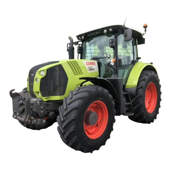
Summary of Contents for Claas ARION 500
- Page 1 ARION 650-620 CMATIC ARION 550-530 CMATIC Repair manual...
- Page 2 Validity of this repair manual This document is valid for the following tractors: Tractor serial number Description Type from ARION 600 A3700050 — ARION 500 A3500050 —...
-
Page 3: Complete Engine
Complete engine Number Value Note – Description 860 kg — Complete 6-cylinder engine 700 kg — Complete 4-cylinder engine For unspecified tightening torques, refer to the section entitled "Tightening torques". WARNING Lifting heavy components. Risk of death or serious injury. –... - Page 4 Coupling the engine to the chassis Number Value Note – Description 130 N·m + 40° — H, M16 x 2.00 CL 10.9 nut M16 x 2.00 L 80 CL 10.9 stud — Coat the studs with Loctite (638). 50 ± 5 N·m M14 x 1.50 L 82 CL 10.9 stud —...
-
Page 5: Timing Cover
Timing cover 6 cylinders Number Value Note – Description Diagram for applying the flexible seal to the cylinder block. — Use Loctite (515). 8 kg Weight of front panel. 25 N.m Torx® milled head bolts. M10 x 84 studs. Observe the tightening order as illustrated. - Page 6 Number Value Note – Description 97 N.m Oil pressure controller. 120 mm Length of the controller spring. 42.5 mm Length of the controller spring at a tension between 60 and 75 N. For unspecified tightening torques, refer to the section entitled: "Tightening torques". 4 cylinders Number Value...
- Page 7 Number Value Note – Description 60 N.m Access plug to the high-pressure pump pinion. Use a new O-ring. — Oil pressure controller. For unspecified tightening torques, refer to the section entitled: "Tightening torques". CAUTION Contact with very hot liquids or machine parts. Risk of burns ►...
- Page 8 Special tool Tool for fitting and removing the oil pressure controller. No. 60 0500 557 3 Special tool Slide hammer No. 77 0138 805 8 Removing the timing cover ► Drain the engine oil. ► Remove the sump.
- Page 9 Sump ► Remove the fan and its support. Ventilation and beltsFunction:01 Engine ► Remove the fan belt tensioner (1) and the roller (2). Ventilation and beltsFunction:01 Engine ► Remove the water pump (3). Water pump ► Remove the crankshaft torsional absorber (4). Crankshaft torsional absorber ►...
- Page 10 Note the position of the bolts and nuts before removing them. ► Remove the bolts (1) and nuts (2) of the timing cover. On a 4-cylinder engine, remove the bolt (3) located behind the front panel. ► Remove the timing cover. Removing the front panel On a 4-cylinder engine, remove the oil pressure controller.
- Page 11 ► Remove the lower intermediate pinion (5). ► Remove the oil pump (6). On a 4-cylinder engine, remove the two balancer shafts (7). Balancer shaft ► Remove the studs (1). On a 6-cylinder engine, remove the bolt (2). ► Remove the Torx® milled head bolt (3). ►...
- Page 12 Respect the technical specifications from the overview. ► Fit the front panel. ► Fit the bolts (3) and studs (1) and tighten them to the recommended torque, respecting the tightening order. On a 6-cylinder engine, fit and tighten the bolt (2) to the recommended torque. On a 4-cylinder engine, set the timing of the balancer shafts (7) and lower intermediate pinion (5).
- Page 13 Timing cover ► Fit the timing cover. ► Fit the high-pressure injection pump (2). High-pressure pump ► Fit the thermostat unit if it was removed. Thermostat unit Fitting the timing cover Respect the technical specifications from the overview. ► Install a new seal (1) and fit the timing cover (2). ►...
- Page 14 ► Fit the crankshaft position sensor (B231) (2). SensorsFunction:01 Engine ► Fit and tighten the bolts (1) securing the clamps on the wiring harness for the crankshaft position sensor (B231). Respect the technical specifications from the overview. On a 6-cylinder engine, fit the oil pressure controller (5). Timing cover ►...
- Page 15 Ventilation and beltsFunction:01 Engine ► Top up the engine oil. Removing the oil pressure controller 6 cylinders ► Undo the pressure controller (1). ► Remove the bolt, sealing washer, spring and pressure controller. 4 cylinders ► Remove the timing cover. Timing cover ►...
- Page 16 ► Insert the sleeve (1) of the special tool fully over the valve extractor. ► Using the special tool (1) equipped with a 11/16 – 16 (UNF) threaded end piece, remove the pressure controller (2). Fitting the oil pressure controller 6 cylinders Respect the technical specifications from the overview.
- Page 17 Position the sealing washer (1) in the right direction as illustrated. ► Insert the pressure controller assembly in the opening in the timing cover. ► Tighten the pressure controller to the recommended torque. 4 cylinders ► Insert the insertion tool (1) of the special tool in the pressure controller (2). ►...
- Page 18 Engine flywheel housing Number Value Note – Description 70 kg Weight of the engine flywheel housing — Lubricate the camshaft O-ring with clean engine oil The surfaces that will come into contact with the seal must be — clean and dry before fitting M20 x 70 bolt 530 N.m M20 x 100 bolt...
- Page 19 ► Use the jack or stand on a flat, horizontal, sufficiently firm surface. ► Place the jack or stand in a suitable location. WARNING Lifting heavy components. Risk of death or serious injury. – Use lifting equipment that will support the load. –...


Need help?
Do you have a question about the ARION 500 and is the answer not in the manual?
Questions and answers