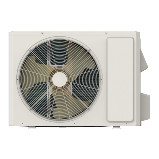
Summarization of Contents
2. Technical Specifications
2.1 Specification Sheet Details
Details technical specifications for indoor and outdoor units, including electrical, mechanical, and performance data.
2.2 Capacity Variation by Temperature
Presents graphical data showing how cooling and heating capacity varies with outdoor temperature.
2.3 Rated Frequency Performance Data
Provides data tables for cooling and heating performance under rated frequency conditions.
3. Outline Dimension Diagrams
3.1 Indoor Unit Dimensions
Provides detailed dimension diagrams and a table for various indoor unit models (ATC, ATD, ATE).
3.2 Outdoor Unit Dimensions
Shows dimension diagrams for different outdoor unit models, including measurements for placement.
4. Refrigerant System Diagrams
Cooling Model Refrigerant Flow
Illustrates the refrigerant flow for cooling-only models, detailing components like compressor, heat exchangers, and valves.
Cooling and Heating Model Refrigerant Flow
Shows the refrigerant circuit for models supporting both cooling and heating, including the 4-way valve.
5. Electrical Diagrams and Layouts
5.1 Wiring Diagrams
Explains wiring symbols and provides wiring diagrams for indoor and outdoor units.
5.2 PCB Printed Diagrams
Shows printed circuit board layouts for indoor and outdoor units, with numbered component references.
6. Functions and Controls
6.1 Remote Controller Operation
Introduces the remote controller, its buttons, display icons, and basic operation.
6.2 GREE+ App Control
Details the control flow and setup for the GREE+ smart app, including OS requirements.
6.3 Ewpe Smart App Control
Explains the control flow and setup for the Ewpe Smart app, including OS requirements and download instructions.
6.4 Modes and Functions Overview
Provides a detailed explanation of various operating modes (Cooling, Drying, Heating, Auto, Fan) and special functions.
7. Installation and Maintenance Safety
Important Safety Precautions
Provides critical safety warnings and guidelines to follow before installation and maintenance.
Electrical Safety Measures
Outlines essential electrical safety measures for installation and maintenance, including power disconnection and grounding.
Installation Safety Guidelines
Lists precautions for selecting installation location, handling units, and ensuring secure mounting.
Refrigerant Handling Safety
Details safety guidelines for handling refrigerants, including leak prevention and proper procedures.
8. Installation Procedures
8.1 Installation Dimension Requirements
Shows diagrams and specifies clearances required for indoor and outdoor unit installation.
Step-by-Step Installation Process
Outlines the step-by-step process for installing the air conditioning unit from start to finish.
8.6 Outdoor Unit Installation
Provides specific instructions and diagrams for mounting and connecting the outdoor unit.
8.2 Installation Parts Checklist
Lists the necessary parts for installation and maintenance to ensure all components are present.
8.3 Installation Location Selection
Guides on choosing appropriate locations for indoor and outdoor units to ensure proper function and avoid issues.
8.4 Electrical Connection Requirements
Details electrical safety, power supply, and grounding requirements for connecting the unit.
8.5 Indoor Unit Installation
Provides specific instructions and diagrams for mounting and connecting the indoor unit.
8.7 Vacuum Pumping and Leak Detection
Explains the procedure for vacuum pumping and detecting refrigerant leaks after installation.
8.8 Post-Installation Checks and Testing
Lists checks to perform after installation to ensure proper setup and verify unit functionality.
9. Troubleshooting and Error Codes
9.1 Error Code Reference
Lists error codes displayed by the unit, their A/C status, and possible causes for troubleshooting.
9.2 Troubleshooting Procedures
Provides systematic diagnostic flowcharts for common malfunctions and component issues.
9.3 Troubleshooting Normal Malfunctions
Offers solutions for common operational issues like unit not starting, poor cooling/heating, or louver problems.
10. Exploded Views and Parts Lists
10.1 Indoor Unit Parts
Displays an exploded view diagram of the indoor unit, with a numbered list of all components and their descriptions.
10.2 Outdoor Unit Parts
Shows an exploded view of the outdoor unit, with a numbered list of parts for identification and replacement.
11. Component Removal Procedures
11.1 Indoor Unit Disassembly
Step-by-step instructions with diagrams for safely removing components of the indoor unit.
11.2 Outdoor Unit Disassembly
Detailed guide with illustrations for disassembling the outdoor unit, component by component.
Appendix: Technical References
Appendix 1: Temperature Conversion Chart
Provides conversion tables between Celsius and Fahrenheit for temperature readings.
Appendix 2: Connection Pipe Configuration
Details pipe specifications, length limitations, and refrigerant charging amounts based on pipe diameter.
Appendix 3: Pipe Expanding Method
Explains the correct procedure for expanding pipes to prevent refrigerant leakage, including cutting and shaping.
Appendix 4: Temperature Sensor Resistance Values
Offers resistance tables for temperature sensors at various temperatures, used for diagnosing sensor faults.


Need help?
Do you have a question about the GWH12AT and is the answer not in the manual?
Questions and answers