
Related Manuals for Genesys ADMA-Speed


Summary of Contents for Genesys ADMA-Speed
- Page 1 User Manual ADMA-G ADMA-Speed ADMA-Slim Hardware V3.0 Firmware-Version 30.9.X.X GeneSys Elektronik GmbH Offenburg...
- Page 2 USER MANUAL Note GENESYS ELEKTRONIK strives to maximize the accuracy of all its data and specifications but cannot rule out the possibility of errors and reserves the right to future modifications without any prior notice. GENESYS ELEKTRONIK is not obliged to maintain secrecy over any received material or other information in the absence of any corresponding agreements made with GENESYS ELEKTRONIK prior to submission of such information.
-
Page 3: Table Of Contents
ADMA 3.0 USER MANUAL TABLE OF CONTENTS INTRODUCTION ADMA PRODUCT FAMILY ADMA-G ADMA-SPEED ADMA-SLIM ORDERING OPTIONS SCOPE OF DELIVERY ADMA-G COMPONENTS ADMA-SPEED COMPONENTS ADMA-SLIM COMPONENTS FRONT VIEW AND INTERFACES ADMA-G ADMA-SPEED ADMA-SLIM ADMA WEBINTERFACE TPC/IP SETTINGS CONNECT TO THE ADMA WEBINTERFACE... - Page 4 ADMA 3.0 USER MANUAL OPERATIONAL CONFIGURATIONS OVERVIEW OF POSSIBLE CONFIGURATIONS WITH ADMA TEST MANOEUVRES AND OPERATING CONFIGURATIONS RECEIVER SETTINGS DGNSS OPTIONS STEERING AND DRIVING ROBOT DATA OUTPUT SIGNAL OUT SIGNAL IN EXTERNAL VELOCITY RAW DATA RECORDING FOR POST-PROCESSING MEASUREMENT DATA 10.1 UTILISED COORDINATE SYSTEMS 10.2...
- Page 5 ADMA 3.0 USER MANUAL NOTES AND DRAWINGS TABLE OF FIGURES TABLE OF DIAGRAMS REVISION HISTORIE Document Revision 2.01 | 2021 Page 5/137...
-
Page 6: Introduction
ADMA 3.0 USER MANUAL Introduction This user manual serves as an aid in commissioning the ADMA (Automotive Dynamic Motion Analyzer) gyro system. The first part of the manual describes a routine for testing whether the ADMA gyro system's inertial sensors are operating without error. This function test is also a good way to become familiar with ADMA and to gain experience in setting up the ADMA. -
Page 7: Adma Product Family
Manual are available with ADMA-Speed or ADMA-Slim. Each distinction between ADMA- G, ADMA-Speed and ADMA-Slim is explained in this Manual. • Some functions require a license. Therefore, refer to the technical specifications of your device. ADMA-G-Pro+ ADMA-G-ECO ADMA-G ADMA-G-ECO+ ADMA-G-EntryLevel... -
Page 8: Adma-G
USER MANUAL 2.1 ADMA-G The ADMA-G models differ in performance of the applied inertial sensors. Higher precision sensors are less sensitive to GNSS interference or outages. Our gyro system does not require an export license. All models are available with variable GNSS accuracy, ranging from simple L1 receivers with meter accuracy to L1/L2 RTK receivers with centimeter accuracy. -
Page 9: Scope Of Delivery
ADMA 3.0 USER MANUAL Scope of delivery 3.1 ADMA-G components ADMA products are completely supplied including basic cables, GNSS antenna, software and manual. Other components are available, please contact us for more information. Description ADMA-G module ■ ■ ■ ADMA power cable ■... -
Page 10: Adma-Speed Components
ADMA 3.0 USER MANUAL 3.2 ADMA-Speed components ADMA-Speed product is completely supplied including basic cables, GNSS antenna, software and manual. Other components are available, please contact us for more information. Description ADMA-Speed control unit ■ ADMA-Speed sensor unit ■ ADMA-Speed power cable ■... -
Page 11: Adma-Slim Components
ADMA 3.0 USER MANUAL 3.3 ADMA-Slim components ADMA-Slim LEMO, MIL and OEM product is completely supplied including basic cables, GNSS antenna, software and manual. Other components are available, please contact us for more information. Description ADMA-Slim module ■ ■ □ ADMA power cable ■... -
Page 12: Front View And Interfaces
ADMA 3.0 USER MANUAL Front view and interfaces 4.1 ADMA-G Figure 2 ADMA-G front view Interface Description Ethernet 1 Interface for ADMA data output, configuration and firmware update, steering and driving robot data output, optional for relative data calculation (e.g. range) and DGNSS routing, input/output. - Page 13 GNSS Ant 2 Secondary GNSS Antenna (for Dual Antenna Systems) 9-32V DC In 12 VDC nominal supply voltage (input voltage range 9 - 32 VDC) Load dump protection 4.1.1 Status operating mode ADMA-G Port Description 9-32 V DC IN No supply voltage ⚫...
-
Page 14: Adma-Speed
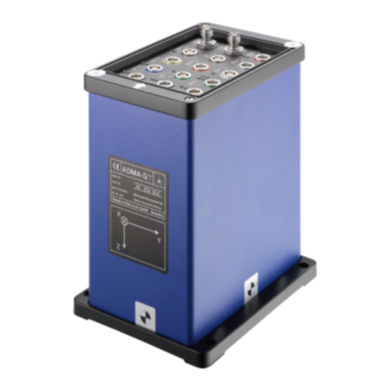
ADMA 3.0 USER MANUAL 4.2 ADMA-Speed Figure 3 ADMA-Speed front view Interface Description Ethernet 1 Interface for ADMA data output, configuration and firmware update, steering and driving robot data output, optional for relative data calculation (e.g. range) and DGNSS routing, input/output. Ethernet 2 Interface for driving robot data output, optional for relative data calculation (e.g. - Page 15 ADMA 3.0 USER MANUAL 4.2.1 Status operating mode ADMA-Speed Port Description 9-32 V DC IN No supply voltage ⚫ ⚫ 9-32 V DC IN Supply voltage connected ⚫ ⚫ ADMA boot process started 9-32 V DC IN Ready for operation ⚫...
-
Page 16: Adma-Slim
ADMA 3.0 USER MANUAL 4.3 ADMA-Slim Figure 4 ADMA-Slim Lemo version and ADMA-Slim MIL version front view Interface Description Ethernet For data output, configuration and firmware update, steering and driving robot data output, optional for relative data calculation (e.g. range) and DGNSS routing, input/output. - Page 17 ADMA 3.0 USER MANUAL 4.3.1 Status operating mode ADMA-Slim Port Description Power No supply voltage ⚫ 9-32 V DC IN ⚫ Supply voltage connected Core Status No supply voltage ⚫ ⚫ Ready for operation ⚫ booting Data output via COM ⚫...
-
Page 18: Adma Webinterface
ADMA 3.0 USER MANUAL ADMA Webinterface The ADMA provides options for certain user-specific and operational settings / configurations. On application of the supply voltage, the system runs through an initialization phase which ends in standby mode. Then the available settings and configuration parameters of the ADMA can be modified via Webinterface http://192.168.88.30. -
Page 19: Tpc/Ip Settings
ADMA 3.0 USER MANUAL 5.1 TPC/IP settings The Webinterface is integrated in the ADMA. For access, the following settings of the network connection must be done: Open Network Connections by clicking the Start button . Then click Control Panel. Open Network and Sharing Center click View network connections. -
Page 20: Figure 6 The Internet Protocol Version 4 (Tcp/Ipv4) Properties Dialog Box
ADMA 3.0 USER MANUAL To specify an IP address, click Use the following IP address, and then, in the IP address, Subnet mask, and type in the following IP address settings: IP – Adress: 192.168.88.XXX Subnet mask: 255.255.255.0 Figure 6 The Internet Protocol Version 4 (TCP/IPv4) Properties dialog box To check your settings, please start the internet browser of your computer. -
Page 21: Connect To The Adma Webinterface
ADMA 3.0 USER MANUAL 5.2 Connect to the ADMA Webinterface To access the ADMA Webinterface, enter http://192.168.88.30 in the address bar of your browser. For an easy handling of the ADMA Webinterface, an interactive help has been implemented. All adjustable parameters in the configuration mode are accompanied with a short hint which will be displayed on the right-hand side of the Webinterface. -
Page 22: Adma Laboratory Bench Test
ADMA 3.0 USER MANUAL ADMA laboratory bench test The routine described below is intended to test the functionality of the inertial sensors of the gyro system, i.e. the accelerometers and gyroscopes. This function test is also a good way to become familiar with the ADMA and to gain experience in setting up the ADMA via Webinterface. -
Page 23: Adma Configuration For Bench Testing
ADMA 3.0 USER MANUAL 7.2 ADMA configuration for bench testing 7.2.1 Configuring measurement data transmission via the CAN interface Go to menu DATA LINK . Activate CAN data out for testing. This sets up the ADMA to transmit the data via the CAN port. Please note, that COM and CAN mode can only be used exclusively! The default CAN settings are: •... -
Page 24: Figure 10 Dialog: Data
ADMA 3.0 USER MANUAL 7.2.2 Selection of data packets to be transmitted The Data dialog is used to individually select the data packets which shall be transmitted by the ADMA. Data packets which are not required can be deactivated in order to reduce the transmission data volume. -
Page 25: Figure 11 Dialog: Auxiliary Systems
ADMA 3.0 USER MANUAL 7.2.3 Auxiliary systems This dialog is used to specify parameters which are related to auxiliary systems such as DGNSS settings and external velocity systems. For the function test, it is necessary to deactivate all auxiliary systems as described below: •... -
Page 26: Figure 12 Dialog: Parameters
ADMA 3.0 USER MANUAL 7.2.4 Parameters The values of roll and pitch angle misalignment should be determinate via Auto Roll/Pitch alignment. Figure 12 Dialog: Parameters Page 26/137 Document Revision 2.01 | 2021... -
Page 27: Figure 13 Dialog: Load / Save / Start
ADMA 3.0 USER MANUAL 7.2.5 Save settings to ADMA The altered settings must be saved to the ADMA. This modified configuration can be saved on the hard disk for further tests. For this purpose, klick on Download. Figure 13 Dialog: Load / Save / Start Document Revision 2.01 | 2021 Page 27/137... -
Page 28: Figure 14 Start Measurement
ADMA 3.0 USER MANUAL 7.2.6 Starting measurement Please specify a pre-alignment duration of 10 seconds. To start a measurement, select Start measurement from the LOAD/SAVE/START menu. Start measurement will save settings as well. Figure 14 Start Measurement Page 28/137 Document Revision 2.01 | 2021... -
Page 29: Setup The Data Acquisition (Daq)
ADMA 3.0 USER MANUAL 7.3 Setup the Data Acquisition (DAQ) Configure your CAN device and load the GeneSys ADMA DBC Library v3.3.x in your Data Acquisition Software. Pre-alignment in progress data channel Status_Alignment and Status_Count is indicated as shown below. -
Page 30: Static Test
ADMA 3.0 USER MANUAL 7.4 Static test 7.4.1 Transient condition of the Kalman filter The Kalman filter of the ADMA can be activated without auxiliary systems like an external velocity or a (D)GNSS. It is possible to experience transient effects in the first few minutes (60-120 seconds). After this transient phase, stable values will be shown. -
Page 31: Figure 17 Checking The Accelerations
ADMA 3.0 USER MANUAL 7.4.3 Checking the accelerations The ADMA should be positioned on a laboratory bench or similar facility, thus being placed on a close to horizontal surface. In addition, keep a flat support surface ready so that the ADMA remains level even when tilted. -
Page 32: Figure 18 Checking The Rate Values
The measured rotational speed of all axis should be between ±0,1°/s. Without special software and hardware, it is not possible to test gyros accurately, so it is necessary to send the ADMA to GeneSys for calibration on a regular basis. Page 32/137... -
Page 33: Dynamic Test
ADMA 3.0 USER MANUAL 7.5 Dynamic Test As part of the dynamic test, the ADMA undergoes defined linear and rotary motion, i.e. along or about the systems sensor axis. The rotational speeds are checked first, beginning with the X-axis (roll), followed by the Y (pitch) and (yaw) axes, and then followed by the acceleration check in the same sequence of axes. - Page 34 ADMA 3.0 USER MANUAL 7.5.2 Checking the accelerations The system should be move linearly along the individual axes in the sequence X, Y and Z. The plotted data could appear as follows: Diagram 2 Plot - Accelerations body X/Y/Z This data plot shows that ADMA detects negative as well as positive accelerations along the three measurement axes.
-
Page 35: Installation And Cabling Inside The Vehicle
ADMA. Safe and secure installation of the ADMA is essential to receive reliable data. Figure 19 ADMA-G point of installation The GNSS antenna must be mounted on the roof of the vehicle. For best performance, it is necessary to mount the GNSS antenna(s) away from any object that may shadow the satellite signal. -
Page 36: Figure 20 Adma-Speed Point Of Installation
ADMA 3.0 USER MANUAL 8.1.2 ADMA-Speed Mount the ADMA-Speed antenna in a suitable position on the roof of the vehicle. The ideal position is in the front or back of the roof, on a rigid area away from any objects that may shadow the GNSS signal such as roof bars. -
Page 37: Figure 23 Adma-Slim With Detached Gnss Antenna
ADMA 3.0 USER MANUAL 8.1.3 ADMA-Slim The ADMA-Slim can be installed in a suitable position anywhere in or on the roof of the vehicle. The GNSS antenna must be mounted on the roof of the vehicle. For best performance, it is necessary to mount the GNSS antenna(s) away from any object that may shadow the satellite signal. -
Page 38: Figure 25 Adma-Slim Fixture Kit For Gnss Antenna Mounting
ADMA 3.0 USER MANUAL 8.1.3.1 ADMA-Slim fixture kit for GNSS antenna mounting Figure 25 ADMA-Slim fixture kit for GNSS antenna mounting The ADMA-Slim default mounting offsets with fitted GNSS antenna are: Figure 26 ADMA-Slim / (6) Parameter / Mounting offset position fitted GNSS Antenna 8.1.3.2 ADMA-Slim magnets for car roof mounting Figure 27 ADMA-Slim magnets for car roof mounting Page 38/137... -
Page 39: Figure 28 Dual Antenna Mounting
We recommend to keep the system at least 30 cm away from glass surface or outer edges of the vehicle. • It is important that both antennas are from GeneSys and of the same type. Using two different types of antenna may cause the solution to fail. •... -
Page 40: Figure 29 Ideal Antenna Installation Distance Of 1M To Each Other
ADMA 3.0 USER MANUAL 8.1.5 External velocity measuring system Usually, the external speed measuring system is attached to one side of the vehicle. For slalom tests involving a higher risk of damage to the sensor, a point at the front / rear of the vehicle can be used. 8.1.6 Auxiliary antennas The antennas for the ADMA, GNSS, Radio Modem or GPRS-Modem and Wireless LAN should be spaced out across the roof of the vehicle ideally across around 1 m. -
Page 41: Cabling
Technical Documentation. 8.2.3 ADMA and external velocity measurement ADMA-G systems can process analogue and digital velocity signals - including 2-axis signals - via the External Velocity interface. For this purpose, connect the external velocity sensor to the ADMA-G Ext.Vel. -
Page 42: Figure 30 Ideal Antenna Installation Distance Of 1M To Each Other
ADMA 3.0 USER MANUAL 8.2.4 ADMA and DGNSS For using the DGNSS or RTK-mode of the ADMA a Radio Modem, GSM/GPRS-modem or a Wireless Accesspoint is required to receive correction data. The modem LED indicates the supply of the modem with voltage. -
Page 43: Modify Threshold For Autoinit, Heading Ctrl. And Dual Antenna Use
ADMA 3.0 USER MANUAL 8.3 Modify threshold for AutoInit, Heading ctrl. and Dual Antenna use The AutoInit function of the ADMA is used to automatically set the ADMA inertial states after system start-up, including the yaw angle (Heading). This is only possible with an adequate vehicle velocity, since the yaw angle will be overwritten with the COG (GNSS Course Over Ground) value. -
Page 44: Standstill Detection
ADMA 3.0 USER MANUAL 8.4 Standstill detection The following describes standstill detection thresholds and their correct entry, which will increase the data integrity. Standstill allows a special form of augmentation for use with the Kalman filter, the so called Zero-Velocity-Update. This mode of the Kalman filter update increases the stability of the measurement mode in case of standstill. - Page 45 (function “Auto determine Max. rate”) or with a data recording and analyzing the rate signals in standstill. Typical threshold values for standstill detection in passenger cars are: Type Max. rate at standstill [0,1*deg/s] ADMA-G-PRO+ ADMA-ECO/ECO+ ADMA-Speed ADMA-Slim 8.4.3 Max. velocity for standstill detection If the ADMA is operated in a non-solo mode (Ext.
- Page 46 ADMA 3.0 USER MANUAL 8.4.5 Manual determination of the standstill thresholds Standstill detection (Standstill bit) must be “1” with the engine running at vehicle standstill. To determine the maximum rate at standstill, the horizontal rates of the vehicle must be considered at standstill, with the engine running.
-
Page 47: Modify Thresholds For Quality Indication
ADMA 3.0 USER MANUAL 8.5 Modify thresholds for quality indication After starting the measurement, the position-, tilt- and velocity-status is available after 120 sec. This status is based on the Kalman filter’s internal estimation of the quality of the state variable (standard deviation Stddev). - Page 48 ADMA 3.0 USER MANUAL With the GNSS re-entering after a GNSS outage the position quality will increase again. This leads to smaller standard deviations of the ADMA position and thus affecting the position standard deviation. Note: The position error can be reduced to a linear error behaviour by using an external velocity signal. Subsequently, a better position quality can be expected over a certain period of time.
-
Page 49: Relative Coordinate System
ADMA 3.0 USER MANUAL 8.6 Relative Coordinate System The ADMA can output position data referred to a relative coordinate system defined by the user. In order to set a local coordinate system, two parameters are required: • The origin (zero point) of the relative coordinate system defined by latitude and longitude. This origin must be in a area within a few kilometers to achieve the +/-1cm position accuracy. -
Page 50: Figure 35 Adma Web Interface Relative Coordinate System
ADMA 3.0 USER MANUAL The user defined relative coordinates system can be defined via web interface page PARAMETERS \ System Parameters. Enable the user defined relative CS, and type in the latitude, longitude and heading values. The heading angle is the rotation of the X-axes relative to North. For example, leaving this value 0 will set the X-axis to point North, and the Y-axis to West. -
Page 51: Compensating An Adma Misalignment
ADMA 3.0 USER MANUAL 8.7 Compensating an ADMA misalignment 8.7.1 ADMA misalignment As described earlier, an exact alignment of the measurement axes with the vehicle's axes is rarely achieved. However, it is possible to compensate such alignment errors mathematically. Compensation values can be entered in the Offsets dialog in the ADMA Webinterface (menu PARAMETERS). -
Page 52: Compensating The Installation Position
ADMA 3.0 USER MANUAL If a 2-axis speed sensor - for instance, one made by Corrsys - is employed, its mounting can be rotated. The corresponding misalignment can only be determined during a straight-ahead run. Similar to the misalignment in the case of the ADMA, a misalignment causes the vehicle's X-axis speed to produce a component along the sensor's Y-axis. -
Page 53: Figure 36 Dialog: Parameters / Mounting Offsets
ADMA 3.0 USER MANUAL Figure 36 Dialog: Parameters / Mounting offsets Document Revision 2.01 | 2021 Page 53/137... -
Page 54: Figure 37 Dialog: Parameters / Auto Roll / Pitch Setup
ADMA 3.0 USER MANUAL 8.8.1 Mounting offset angle The offset values for the roll axis (X) and the pitch axis (Y) can be determined automatically using the setup function "Auto Roll / Pitch Alignment". The compensation value of the yaw axis (Z) must be entered. -
Page 55: Figure 38 Mounting Offsets Adma-Gnss-Antenna
ADMA 3.0 USER MANUAL 8.8.3 Single antenna mounting offsets The position vector for the GNSS antenna consists of all three components (X, Y, Z) and refers to the ADMA. Figure 38 Mounting offsets ADMA-GNSS-Antenna Document Revision 2.01 | 2021 Page 55/137... -
Page 56: Figure 39 Dual Antenna Mounting
ADMA 3.0 USER MANUAL 8.8.4 Dual antenna mounting offsets The easiest way to install the dual antennas is to place both antennas on the same longitudinal axis at the same height. The primary GNSS antenna should be installed behind the second antenna with a minimum distance of 50 cm to a maximum distance of 200 cm. -
Page 57: Figure 40 Mounting Offsets Primary Gnss Antenna To Adma
ADMA 3.0 USER MANUAL 8.8.4.1 Determining the offset between the GNSS Antennas and ADMA 8.8.4.2 Mounting offsets Primary GNSS Antenna to ADMA The Primary GNSS Antenna always refer to GNSS ANT1 interface of the ADMA. This offset must always be determined. Figure 40 Mounting offsets Primary GNSS Antenna to ADMA Document Revision 2.01 | 2021 Page 57/137... -
Page 58: Figure 41 Mounting Offsets Secondary Gnss Antenna To Primary Gnss Antenna
ADMA 3.0 USER MANUAL 8.8.4.3 Mounting offsets Secondary GNSS Antenna to Primary GNSS Antenna The Secondary GNSS Antenna refers to the Primary GNSS Antenna, in case of lateral and/or height offset between Primary and Secondary GNSS Antenna the offsets must be determined. Figure 41 Mounting offsets Secondary GNSS Antenna to Primary GNSS Antenna 8.8.5 Virtual measuring point (POI - point of interest) If the ADMA is not mounted directly at the required measuring location, then a lever arm exists... -
Page 59: Operational Configurations
ADMA with (D)GNSS. The diagram below depicts these three configurations. External Velocity DGNSS Correction Data Signal IN Signal OUT ADMA-G Steering robot Post Processing Figure 42 Operational configurations – ADMA-G DGNSS Correction Data Signal IN Signal OUT Steering robot ADMA-Speed & ADMA-Slim Post Processing Figure 43 Operational configurations –... -
Page 60: Test Manoeuvres And Operating Configurations
ADMA 3.0 USER MANUAL 9.2 Test manoeuvres and operating configurations A practical operating configuration takes into account the data required for measurement runs as well as the necessary effort for technical preparations. If accurate position data are desired, for instance, the ADMA-DGNSS mode needs to be selected and related set-up tasks need to be performed. -
Page 61: Receiver Settings
ADMA 3.0 USER MANUAL 9.3 Receiver settings At the menu item AUX SYSTEM \ Used Receiver type the receiver to be used can be configured. The following selection options are available depending on the used hardware version: • None (IMU mode) •... -
Page 62: Dgnss Options
ADMA 3.0 USER MANUAL 9.4 DGNSS Options This operating configuration constitutes the most advanced system stage providing the best possible performance. A determination of absolute positions with (D)GNSS allows the most accurate inertial measurement to be performed. Should the reception of the (D)GNSS data be interrupted, position measurement is performed by the ADMA without external augmentation (pure INS operation). -
Page 63: Figure 45 Adma With Differential Corrections
ADMA 3.0 USER MANUAL 9.4.1 Wiring ADMA and DGNSS ADMA-CABLE-SUPPLY-xM [DC In] ADMA-CABLE-SUPPLY-xM Power In [GNSS Ant 1] GNSS Ant. ADMA-CABLE-GPS-xM ADMA-SPEED-CABLE-GPS-xM [GNSS Ant 1] [IMU] GNSS Ant. and ADMA-SPEED-CABLE-IMU-xM [Ethernet 1] ADMA-CABLE-ETH-xM WLAN-Access point ADMA-SPEED-CABLE-ETH-xM DAQ - Ethernet ADMA-CABLE-MODEM-xM [Modem] ADMA-SPEED-CABLE-MODEM-xM Radio Modem e.g. -
Page 64: Figure 46 Dialog: Aux Systems - Dgnss Options
GeneSys BASE - GSM Modem: Receiving of GNSS correction data from GeneSys BASE-Station via GSM Modem. The Correction data format will be detected automatically. GeneSys ADMA – Ethernet: Receiving of GNSS correction data from another ADMA via WLAN. The Correction data format will be detected automatically. (License required) Network Service - NTRIP-Box: Receiving of GNSS correction data from correction data service via NTRIP-DGPS-Box over GSM or GPRS. -
Page 65: Figure 47 Adma With Correction Data Via Base Station
USER MANUAL 9.4.2.1 DGNSS with a Base Station Differential corrections can be supplied by an GeneSys Base Station or other suitable Base Stations. Please see the Technical Documentation of GPS Base Station. Figure 47 ADMA with correction data via Base Station 9.4.2.2 DGNSS correction data via Ethernet... -
Page 66: Figure 49 Adma With Correction Data Via Correction Data Service
9.4.2.3 DGNSS correction data via Network Service Differential corrections can be supplied by GSM or NTRIP via correction data service. Please see the Technical Documentation of GeneSys DGNSS Box. Figure 49 ADMA with correction data via correction data service Page 66/137... -
Page 67: Figure 50 Sbas Systems
ADMA 3.0 USER MANUAL 9.4.2.4 Satellite based GNSS correction data (SBAS) With satellite based correction data (SBAS) the GNSS data accuracy can be improved. The satellites which are used transmitting the correction data. For this reason, signal coverage is only available in certain regions. -
Page 68: Steering And Driving Robot Data Output
ADMA 3.0 USER MANUAL 9.5 Steering and driving robot data output 9.5.1 Wiring ADMA and Steering, driving robot The following diagram shows an example wiring of the ADMA and steering robot. ADMA-CABLE-SUPPLY-xM [DC In] ADMA-CABLE-SUPPLY-xM Power In [GNSS Ant 1] GNSS Ant. ADMA-CABLE-GPS-xM ADMA-SPEED-CABLE-GPS-xM [GNSS Ant 1] [IMU] GNSS Ant. -
Page 69: Figure 52 Abd - Steering Robot
ADMA 3.0 USER MANUAL 9.5.2 Setup and configuration for ABD/Vehico-steering and driving robots You can activate the data output by checking the steering and driving robot output in the configuration dialog Data. Select the protocol version of the used robot to ABD or Vehico from the drop-down list. The sampling rate of the ADMA defines the maximum update frequency of the robot data. -
Page 70: Signal Out
ADMA 3.0 USER MANUAL 9.6 Signal Out The Signal OUT Ports of the ADMA can be used as Digital output. The following functions can be configured via Webinterface for Signal Out Port: • Synchronization output to indicate the ADMA's sampling time point, thus allowing simple synchronization with peripheral measurement systems which can be triggered externally. -
Page 71: Signal In
ADMA 3.0 USER MANUAL 9.7 Signal In The Signal In Ports of the ADMA can be used as: • Synchronization input to receive clock signals from an external data recording or measurement system to permit offline synchronization with other data sources. Note: This input only registers one pulse per ADMA cycle. -
Page 72: External Velocity
ADMA 3.0 USER MANUAL 9.8 External velocity If the ADMA is supplied with an external velocity signal, the orientation angles for roll and pitch do not drift, thus permitting measurements over longer periods. Supply of an external velocity signal allows the ADMA to calculate a relative position using the method of dead reckoning. -
Page 73: Figure 54 Example Wiring Diagram Of The Adma And External Velocity
ADMA 3.0 USER MANUAL 9.8.1 Wiring external velocity The following diagram shows an example wiring of the external velocity and data logging via Ethernet for use with GeneSys “ADMA-PP” Post Processing Software. ADMA-CABLE-SUPPLY-xM [DC In] Power In ADMA-CABLE-GPS-xM [GNSS Ant 1]... -
Page 74: Figure 55 Dialog: Aux. Systems - Configuration Of The External Velocity
ADMA 3.0 USER MANUAL 9.8.2 Setup and configuration At the dialogue Auxiliary Systems, the external velocity signal for additional support of the Kalman filter can be configured. It is possible to input analog or digital speed sensor signals. Depending on the velocity source. -
Page 75: Raw Data Recording For Post-Processing
GNSS raw data so that these data can subsequently be used in post-processing procedures. For post-processing, GeneSys offers the "ADMA-PP" software incorporating all necessary calculations and Kalman filters. Detailed information about post-processing and ADMA-PP is available from our sales department and distribution partners. -
Page 76: Measurement Data
ADMA 3.0 USER MANUAL Measurement data 10.1 Utilised Coordinate Systems 10.2 Generalities to the utilised coordinate systems Applicable to the coordinate systems used in ADMA (except for the positions): • They are right-handed Cartesian coordinate systems • Direction of rotation by the positive axis direction follows the "right hand rule" 10.2.1 The ADMA measuring axis coordinate system The type label of the ADMA shows the alignment of the measuring axes of the ADMA relative to the housing. -
Page 77: Figure 58 Body Coordinate System
ADMA 3.0 USER MANUAL 10.2.2 The body coordinate system The axes of the body coordinate system are permanently connected to the vehicle, usually to the chassis. The X axis points in the positive direction of travel. The origin of the body coordinate system is identical to the origin of the ADMA measuring axis coordinate system. -
Page 78: Figure 59 Horizontal (Levelled) Coordinate System
ADMA 3.0 USER MANUAL 10.2.3 The horizontal (levelled) coordinate system The axes of the horizontal coordinate system are aligned in such a way that the XY axis level is orthogonal to the acceleration of gravity vector (in the horizon), the X axis alignment is identical to that of the body coordinate system, and the Z axis is parallel to the vector of the gravitational. -
Page 79: Figure 60 Frame (Reference) Coordinate System
ADMA 3.0 USER MANUAL 10.2.4 The frame (reference) coordinate system The frame coordinate system is also known, respectively to the alignment, as the NED coordinate system (North-East-Down). Just as the horizontal coordinate system, the XY axes level is orthogonal to the acceleration of gravity vector. The axes of the reference coordinate system are defined as follows: •... - Page 80 ADMA 3.0 USER MANUAL 10.2.5 Output options for the body and the horizontal coordinate system The ADMA allows defining the output for all horizontal and referenced coordinate systems via Webinterface configuration. There are the following options: The classical (Navigation / SAE) •...
-
Page 81: Orientation Measurement
ADMA 3.0 USER MANUAL 10.3 Orientation measurement The definition of the ADMA yaw, pitch and roll angles follows the Euler angles rules. As defined in the automotive industry standards, former DIN 70000, now DIN 8855, the applied rotational sequences belong to the group of Tait-Bryan rotations around the three coordinate axes. The standards define: Symbol “Ψ”... -
Page 82: Poi-Transformed Adma Data
ADMA 3.0 USER MANUAL 10.4 POI-transformed ADMA data Following the calculation of data valid for the ADMA coordinate system origin, a defined subset of data can be transformed from the ADMA origin to a POI (Point of Interest), even though this requires acceptance of less precision of the transformed data. -
Page 83: Position Information
ADMA 3.0 USER MANUAL 10.5 Position information 10.5.1 WGS84 (World Geodetic System of 1984) Polar coordinates (longitude, latitude, height above mean sea level) are used as a standard technique of indicating positions for worldwide navigation. Most commercial GNSS receivers also output their measured positions in this format. -
Page 84: Figure 63 Height Value
ADMA 3.0 USER MANUAL 10.5.2 ETRS89 (European Terrestrial Reference System) The European Terrestrial Reference System 1989 (ETRS89) is an ECEF (Earth-Centred, Earth-Fixed) geodetic Cartesian reference frame, in which the Eurasian plate as a whole is static. The coordinates and maps in Europe based on ETRS89 are not subject to change due to the continental drift. Since then ETRS89 and ITRS diverge due to the continental drift at a speed about 2,5 cm per year. -
Page 85: Relative, Metric Coordinate System
ADMA 3.0 USER MANUAL 10.6 Relative, metric coordinate system For some applications, it is not useful to specify positions in terms of decimal degrees of longitude and latitude. In this case it would be more helpful to specify positions in meters, for example, to indicate braking distances, radii of steady state circular tests and track deviations. -
Page 86: Measuring Mode
ADMA 3.0 USER MANUAL Measuring mode 11.1 Start sequence After powering up, the system runs through a boot process which ends in standby mode. The ADMA's measuring mode can then be started via the configured data interface or operated with the Start and Stop commands. -
Page 87: Figure 64 Adma Start Sequence
ADMA 3.0 USER MANUAL ADMA start sequence Powering Up Booting Standby condition Start measurement Pre-alignment Auto Init Transient phase of the Kalman Filter Measurement End measurement Figure 64 ADMA start sequence Document Revision 2.01 | 2021 Page 87/137... -
Page 88: System Settings
ADMA 3.0 USER MANUAL 11.2 System settings Use the ADMA Webinterface to configure the system as required for your tests. The following items are parameterized here: • Data interface and (in the case of CAN) advanced options • Sampling frequency, pre-alignment time, autostart, etc. •... -
Page 89: Pre-Alignment
ADMA 3.0 USER MANUAL 11.4 Pre-alignment During pre-alignment, the roll- and pitch angles are calculated from accelerometer data, while the vehicle is at standstill. The duration of the pre-alignment determines the expected precision of the angle estimation. Typical time periods are in the range of 5 - 30 seconds. Make sure the vehicle is not exposed to any other vibrations then the vehicle engine during the pre- alignment period. -
Page 90: Transient Phase Of The Kalman Filter
ADMA 3.0 USER MANUAL 11.5.2 Yaw angle present If the ADMA is operated without GNSS or the ADMA is operating with (D)GNSS but there is no possibility to exceeding the velocity limit for yaw angle initialization, this entry will assure that earth rate is compensated correctly. -
Page 91: Figure 67 Kalman Filter Status Data Packets
ADMA 3.0 USER MANUAL 11.6.1 Kalman filter status The Kalman filter status information provides the transient state of a Kalman filter and indicates whether the system is adjusted, otherwise the specification of the system may not be reached especially in GNSS outage situations. It combines the stimulation of the lateral, longitudinal axis and steady state (acceleration-free state). -
Page 92: Figure 69 Example Kalman Filter Transient Phase Status Estimates
ADMA 3.0 USER MANUAL • Velocity Horizontal X [km/h] • Velocity Horizontal Y [km/h] • KF Lateral stimulation [%] • KF Longitudinal stimulation [%] • KF steady state [%] Figure 69 Example Kalman Filter transient phase status estimates If the Kalman filter status does not reach the 100% it can be caused by: •... -
Page 93: Add-On And Add-In
ADMA 3.0 USER MANUAL Add-On and Add-In 12.1 Add-On - DELTA Data The DELTA Data is an additional functionality (Add-On) of the ADMA. There are two ADMA’s needed: • one for the Target vehicle (called EGO-ADMA) and • one for the Hunter vehicle (called DELTA-ADMA) The DELTA ADMA computes internal relative data calculations of distance, velocity and angle between the two vehicles. -
Page 94: Figure 71 Delta Measurement Detailed
ADMA 3.0 USER MANUAL 12.1.1 DELTA Measurement Figure 71 DELTA Measurement detailed Page 94/137 Document Revision 2.01 | 2021... - Page 95 ADMA 3.0 USER MANUAL The DELTA Add-On calculates the distance between two moving vehicles. The measurement reference point is in the coordinate system of the DELTA-ADMA vehicle (Hunter vehicle). In this coordinate system, the Longitudinal direction (x direction) of the DELTA-ADMA is the INS-Angle- YAW.
-
Page 96: Figure 72 Example Wiring Diagram Of The Delta-Adma
ADMA 3.0 USER MANUAL 12.1.2 Wiring DELTA-ADMA The following diagram shows an example wiring of the DELTA-ADMA (Hunter vehicle). ADMA-CABLE-SUPPLY-xM [DC In] ADMA-CABLE-SUPPLY-xM Power In [GNSS Ant 1] GNSS Ant. ADMA-CABLE-GPS-xM ADMA-SPEED-CABLE-GPS-xM [GNSS Ant 1] [IMU] GNSS Ant. and ADMA-SPEED-CABLE-IMU-xM [Ethernet 1] ADMA-CABLE-ETH-xM WLAN-Access point... -
Page 97: Figure 74 Example Of Adma Add-On Delta Configuration
ADMA 3.0 USER MANUAL 12.1.4 Network configuration The ADMA’s communicate via UDP. The ADMA use datagram sockets to establish host-to-host communications. An application binds a socket to its endpoint of data transmission, which is a combination of an IP address and a service port. A port is a software structure that is identified by the port number, a 16 bit integer value, allowing for port numbers between 1024 and 65535. -
Page 98: Figure 75 Delta Measurement Poi
ADMA 3.0 USER MANUAL 12.1.5 Point of Calculation The DELTA Add-On calculate the delta values between the defined POI at the Ego-ADMA and POI at the DELTA-ADMA. This allows to compare the DELTA data directly with the VUT (Vehicle under Test) sensor measurements. -
Page 99: Figure 76 Delta Lateral Offset
ADMA 3.0 USER MANUAL 12.1.6 Offset Corrections In some cases, an offset correction of the lateral or longitudinal distance can be useful. To make a quick adjustment, user defined offset values can be added or subtracted from the lateral or longitudinal distance. - Page 100 ADMA 3.0 USER MANUAL 12.1.7 CAN recurrence interval The CAN recurrence interval determines how long the last valid DELTA value is repeated after a loss of the EGO data (Target data) until the DELTA result is output with 0. Example 1: Configured CAN recurrence interval of 100 msec with an ego data loss over 100 msec. ADMA-DELTA CAN 100msec recurrence interval 2,20 2,15...
-
Page 101: Add-On - Braking Data
ADMA 3.0 USER MANUAL 12.2 Add-On - Braking Data The Braking Data is an additional functionality (Add-On) of the ADMA. The Add-On allows you to output the result of braking data in high-accuracy via CAN or Ethernet interface. Note: For being authorized using the Braking Data a license is required. There are two main conditions for start/stop of braking distance measurement: Externally triggered e.g. -
Page 102: Figure 78 Genesys Ethernet Logger
USER MANUAL 12.2.2 Live results A Laptop or tablet PC running GeneSys UDP Logger software can be used to monitor the measured parameters in real time by using an Ethernet connection. All braking results can be stored as result chart and full data stream. This allows a detailed post processing. -
Page 103: Figure 79 Add-Ons / Braking Data
ADMA 3.0 USER MANUAL 12.2.3 Setup and configuration Configuration of the setup criteria can be set on menu ADD-ONS / Braking Data. Figure 79 ADD-ONS / Braking Data Document Revision 2.01 | 2021 Page 103/137... -
Page 104: Figure 80 Lever Arms
ADMA 3.0 USER MANUAL Data source Configure the reference point for braking distance calculation. To define the lever arms for POI1 please choose menu PARAMETERS. The image below shows the lever arm effect. Figure 80 Lever arms Braking Counter Reset The braking counter can be reset via external signal at Signal IN2 interface. -
Page 105: Figure 81 Main Braking Measurement
ADMA 3.0 USER MANUAL Example of a main braking measurement external and velocity triggered. Figure 81 Main braking measurement Document Revision 2.01 | 2021 Page 105/137... -
Page 106: Figure 82 Main And Intermediate Braking Measurement
ADMA 3.0 USER MANUAL Example of a main and intermediate braking measurement, external and velocity triggered. Figure 82 Main and Intermediate braking measurement Page 106/137 Document Revision 2.01 | 2021... -
Page 107: Figure 83 Fading Test
ADMA 3.0 USER MANUAL Example of a fading test procedure. Main braking measurement conditions, external and velocity triggered with activated “stop at external trigger”. The start velocity of the intermediate braking measurement is equal to the main start velocity. Figure 83 Fading Test Document Revision 2.01 | 2021 Page 107/137... -
Page 108: Figure 84 Intermediate Braking Window
ADMA 3.0 USER MANUAL Intermediate Window Start/Stop conditions The velocity limits should be between or equal to the main velocity window. They represent only a partial result and did not terminate the measurement. Figure 84 Intermediate Braking Window Page 108/137 Document Revision 2.01 | 2021... - Page 109 ADMA 3.0 USER MANUAL 12.2.4 Calculations Velocity averaging time Calculates the average velocity over x msec before external trigger event. Only supported on arming method according DIN70028. Normalizing velocity Normalizing velocity is a concept that takes dynamics out of the equation when calculating performance trends.
-
Page 110: Figure 85 Example Table Automatic Start Velocity
ADMA 3.0 USER MANUAL Abort conditions for measurement Defines abort conditions for braking distance measurement abort. Automatic start velocity Depending on the velocity at external trigger, the upper velocity (starting speed) will be automatically set to the next full 5km/h or 10km/h digit. Next full 5km/h threshold Next full 10km/h threshold Velocity at Start... -
Page 111: Add-On - Filter
ADMA 3.0 USER MANUAL 12.3 Add-On - Filter The Add-On Filter allows to filter ADMA acceleration and angular rates before output on the Ethernet or CAN interface. As a reproduction of true movements of the vehicle, accelerations and rotation rates of the measurement data may appear noisy. -
Page 112: Figure 88 Filter Frequency Response Example (Butterworth; Order 6; Cut-Off 10Hz)
ADMA 3.0 USER MANUAL The following diagram (Figure 88) shows an example of the frequency response of an 6th order Butterworth filter with a cut off frequency of 10Hz. Applied to the acceleration body in X axis, the curve shown as an example in the diagram (Figure 89) below results in comparison to the unfiltered acceleration signal Body X HR. -
Page 113: Add-In - Correction Data Forwarding
ADMA 3.0 USER MANUAL 12.4 Add-In - Correction Data Forwarding The DGNSS correction data forwarding is a free additional functionality (Add-In) of the ADMA. Note: For being authorized receiving DGNSS correction data via ethernet a license is required. The DGNSS correction data forwarding functionality of the ADMA allows to transmit correction data from one ADMA to another. -
Page 114: Figure 91 Example Wiring Diagram Of The Adma
ADMA 3.0 USER MANUAL 12.4.1 ADMA wiring The following diagram shows an example wiring of the Master-ADMA. ADMA-CABLE-SUPPLY-xM [DC In] ADMA-CABLE-SUPPLY-xM Power In [GNSS Ant 1] GNSS Ant. ADMA-CABLE-GPS-xM ADMA-SPEED-CABLE-GPS-xM [GNSS Ant 1] [IMU] GNSS Ant. and ADMA-SPEED-CABLE-IMU-xM [Ethernet 1] ADMA-CABLE-ETH-xM WLAN-Access point ADMA-SPEED-CABLE-ETH-xM... -
Page 115: Figure 92 Example Of Adma Dgnss Correction Data Forwarding
IP-Address: 192.168.88.50 IP-Address: 192.168.88.60 ❸ DATA ❺ AUX SYSTEMS DGNSS correction data forwarding DGNSS options ADMA Interface: Ethernet 1 DGNSS Preset: GeneSys ADMA Ethernet Destination IP: 192.168.88.255 *1 Source: Ethernet 1 Destination Port: 1126 Source IP: 192.168.88.50 Source Port: 1126... -
Page 116: Add-In - Correction Data Via Ethernet
Figure 93 ETH DGNSS Correction data forwarded via ADMA Option B: GeneSys Base Station via WLAN Figure 94 ETH DGNSS Correction data via GeneSys Base Station Note: For being authorized using DGNSS correction data via ethernet a license is required. -
Page 117: Figure 95 Example Wiring Diagram Of The Adma
[CAN1] ADMA-SPEED-CABLE-CAN-xM CAN-CASE Figure 95 Example wiring diagram of the ADMA The following diagram shows an example wiring of the GeneSys Base Station. [GPS Ant 1] GPS Ant. [Ethernet 1] WLAN-Access point Figure 96 Example wiring diagram of the Base Station Document Revision 2.01 | 2021... -
Page 118: Figure 97 Example Of Adma Dgnss Correction Data Form Genesys Base Station
Option A: Receiving correction data forwarded from another ADMA via WLAN see chapter 12.4 Add- In - Correction Data Forwarding. Option B: Receiving correction data form a GeneSys Base Station via WLAN. The following diagram shows an example configuration of the DGNSS correction data via Ethernet from a GeneSys Base Station. -
Page 119: Add-In - Gnss Raw Data Via Ethernet
Note: For being authorized using GNSS Raw data via Ethernet a license is required. The GNSS Raw Data via Ethernet functionality of the ADMA allows to transmit the GNSS receiver raw data via Ethernet for post processing (GeneSys ADMA-PP). The data can be received via GeneSys UDP Logger Software. -
Page 120: Figure 99 Example Of Gnss Raw Data Via Ethernet
ADMA 3.0 USER MANUAL 12.6.2 Setup and configuration The following diagram shows an example configuration of the DGNSS Raw Data logging via Ethernet. ADMA ❷ DATA LINK Ethernet Settings Ethernet Settings IP-Address: 192.168.88.100 IP-Address: 192.168.88.30 ❸ DATA Ethernet Logger Software Ethernet Data Output ADMA IP: 192.168.88.30... -
Page 121: License Management
ADMA 3.0 USER MANUAL License management The menu system offers the possibility for easy license handling and gives you an overview of all registered license options. The ADMA usually is delivered with a valid license, tied to the hardware. If you purchased an Add-On or Add-In option afterwards, you would get a license key file. -
Page 122: Firmware Updates
USER MANUAL Firmware Updates 15.1 ADMA - Firmware Update GeneSys Elektronik GmbH continuously releases free firmware updates for the ADMA. These firmware updates include enhancements to existing features and often new features for your ADMA. 1. Connect the Ethernet 1 interface of the ADMA with your network interface of your PC. -
Page 123: Gnss-Receiver - Firmware Update
Please see the following step by step instruction for GNSS receiver update: 15.2.1 Step 1: Wiring To be able to access the GNSS receiver connect the provided ADMA Modem to SubD9-Cable (ADMA- G and ADMA-Speed) or ADMA AUX to SubD9-Cable (ADMA-G only) with the serial interface of your computer. ADMA-CABLE-SUPPLY-xM... -
Page 124: Figure 103 Adma Configuration For The Gnss-Receiver Firmware Update
ADMA 3.0 USER MANUAL 15.2.2 Step 2: Setup and Configuration The following settings must be done via ADMA Webinterface: • BEHAVIOUR: Autostart off • DATA LINK: Modem Port or Aux Port Baudrate 115200 baud • AUX SYSTEM: DGNSS Preset off Figure 103 ADMA configuration for the GNSS-Receiver Firmware Update Save settings to ADMA. -
Page 125: Figure 104 Novatel Winload
ADMA 3.0 USER MANUAL 15.2.3 Step 3: Firmware Update Unzip the firmware update files and start the application WinLoad, which is located in the unzipped folder. • Unzip • Start WinLoad Figure 104 Novatel WinLoad Always use the WinLoad application contained in the *.ZIP file! Document Revision 2.01 | 2021 Page 125/137... -
Page 126: Figure 105 Novatel Winload Com Port Setup
ADMA 3.0 USER MANUAL Go to Settings / COM Settings... Select the used COM Port on your computer and enter the baud rate as shown in the following image: Figure 105 Novatel WinLoad COM Port Setup Open the **RN000.SHEX file via file menu File / Open Script File... Figure 106 Novatel WinLoad open *.SHEX file Page 126/137 Document Revision 2.01 | 2021... -
Page 127: Figure 107 Novatel Winload Start Write Flash
ADMA 3.0 USER MANUAL Click on the button Write Flash (1). Figure 107 Novatel WinLoad start Write Flash As soon as the dialog box on the display shows "Searching for card ... timeout in: 30 secs" (2), press the Button "Send Command"... -
Page 128: Figure 109 Novatel Winload Downloading
ADMA 3.0 USER MANUAL The Firmware Update will now be in progress. This might take a few minutes. Figure 109 Novatel WinLoad downloading Do not disconnect the link between ADMA and computer or power supply during the Firmware Update! Figure 110 Novatel WinLoad downloading done Power reset the ADMA to complete the Firmware Update. -
Page 129: Figure 111 Adma Page System Gnss Receiver Information
ADMA 3.0 USER MANUAL To check the successful Firmware Update, connect to the ADMA Webinterface. Start Measurement and open the menu SYSTEM, GNSS receiver Information, Firmware Version. Figure 111 ADMA page System GNSS Receiver Information Document Revision 2.01 | 2021 Page 129/137... -
Page 130: Figure 112 Note Your Mounting Offsets X/Y
ADMA 3.0 USER MANUAL Notes and drawings POI1 Figure 112 Note your mounting offsets X/Y Figure 113 Note your mounting offsets Z Page 130/137 Document Revision 2.01 | 2021... -
Page 131: Figure 114 Note Your Mounting Offsets X/Y
ADMA 3.0 USER MANUAL POI1 Figure 114 Note your mounting offsets X/Y Figure 115 Note your mounting offsets Z Document Revision 2.01 | 2021 Page 131/137... - Page 132 ADMA 3.0 USER MANUAL Page 132/137 Document Revision 2.01 | 2021...
- Page 133 ADMA 3.0 USER MANUAL Document Revision 2.01 | 2021 Page 133/137...
- Page 134 Figure 16 Status Standstill and Error Hardware ..............30 Figure 17 Checking the accelerations .................. 31 Figure 18 Checking the rate values ..................32 Figure 19 ADMA-G point of installation ................35 Figure 20 ADMA-Speed point of installation ................. 36 Figure 21 ADMA-Speed point of installation ................. 36 Figure 22 ADMA-Speed / (6) Parameter / Mounting offset position fitted GNSS antenna .....
- Page 135 Figure 95 Example wiring diagram of the ADMA ..............117 Figure 96 Example wiring diagram of the Base Station ............117 Figure 97 Example of ADMA DGNSS correction data form GeneSys Base Station ....118 Figure 98 Example wiring diagram of the ADMA ..............119 Figure 99 Example of GNSS Raw Data via Ethernet .............
- Page 136 ADMA 3.0 USER MANUAL Figure 106 Novatel WinLoad open *.SHEX file ..............126 Figure 107 Novatel WinLoad start Write Flash ..............127 Figure 108 ADMA page System Reset GNSS Receiver for Firmware Update ......127 Figure 109 Novatel WinLoad downloading ................128 Figure 110 Novatel WinLoad downloading done ..............
- Page 137 Add description of the Kalman filter status information. • Add system type ADMA-Slim. • More detailed application and system descriptions. V 1.7 • Merged ADMA-G and ADMA-Speed manuals. • More detailed description of Add-On and operational functions Document Revision 2.01 | 2021 Page 137/137...
Need help?
Do you have a question about the ADMA-Speed and is the answer not in the manual?
Questions and answers