Advertisement
CONFIDENTIAL
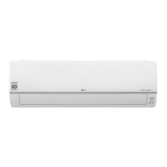
Room Air Conditioner
SVC MANUAL (Exploded View)
MODEL : S4-W12JA1ZD.EC6GERU (B12TS.SSJ)
CAUTION
Before Servicing the unit, read the safety precautions in General SVC manual.
Only for authorized service personnel.
Copyright © 2018 LG Electronics Inc. All rights reserved. Only training and service purposes.
Advertisement
Table of Contents

Summarization of Contents
Air Conditioner Specifications
Capacity Specifications
Details on cooling and heating capacity, including rated and T3 conditions.
Power Input and Running Current
Information on power consumption and operational current for cooling and heating modes.
Performance Metrics
Covers EER, COP, and SEER ratings for the air conditioner unit.
Moisture Removal and Air Flow
Specifications for moisture removal rate and air flow rates for indoor and outdoor units.
Indoor Unit Specifications
Dimensions, weight, sound pressure, and sound power level for the indoor unit.
Outdoor Unit Specifications
Dimensions, weight, sound pressure, and sound power level for the outdoor unit.
Refrigerant and Compressor Details
Information on refrigerant type, charge, and compressor specifications.
Heat Exchanger Information
Details on evaporator and condenser materials, fins, and dimensions.
Air Conditioner Functions
Air Flow Control
Features for controlling airflow direction and fan speed.
Air Purifying Features
Details on filters and air purification technologies used in the unit.
Reliability and Operation Modes
Covers self-diagnosis, de-ice control, dry operation, and auto modes.
Convenience and Control Options
Includes timer functions, sleep mode, voice control, and display options.
Energy Saving Functions
Features related to energy efficiency and power management.
Individual and Network Control
Details on wired/wireless controllers, CAC, and network solutions.
Special Functions and Others
Information on special kits, sensors, and other operational modes.
Refrigerant Cycle and Components
Refrigerant Cycle Diagram
Visual representation of the refrigerant flow and major components.
Thermistor Locations
Mapping of thermistor locations (Th1-Th5) to PCB connectors.
Refrigerant Pipe Sizes
Diameters for gas and liquid refrigerant pipe connections.
Component Appendix
Diagrams and labels for various components like EEV, valves, and sensors.
Wiring Diagrams
Indoor Unit Wiring Diagram
Schematic and PCB layout for the indoor unit's electrical connections.
Outdoor Unit Wiring Diagram
Schematic and PCB layout for the outdoor unit's electrical connections.
Exploded Views
Indoor Unit Exploded View
Detailed illustration of indoor unit components with part identification.
Outdoor Unit Exploded View
Detailed illustration of outdoor unit components with part identification.


Need help?
Do you have a question about the B12TS.NSJ and is the answer not in the manual?
Questions and answers