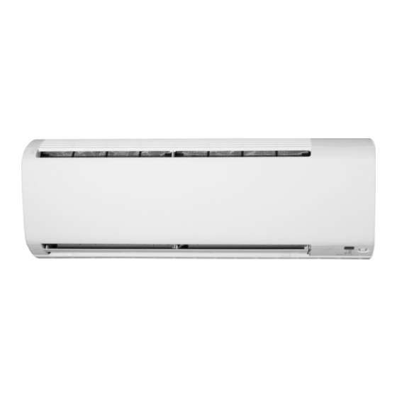
Summarization of Contents
1. Air Filters
1. Remove the air filters.
Procedure to remove the main air filters from the indoor unit.
2. Remove the optional filters.
Procedure to remove optional air filters if available.
2. Front Panel
1. Open the front panel.
Steps to open the indoor unit's front panel to its stopping position.
2. Slide and release the left shaft.
Procedure to slide and release the left shaft of the front panel.
3. Remove the right shaft.
Method to remove the right shaft of the front panel.
4. Remove the front panel.
Final step to detach the front panel from the unit.
3. Front Grille
1. Remove screw covers and screws.
Instructions for removing screws and their covers on the front grille.
2. Unfasten top hooks.
Steps to unfasten the three hooks securing the front grille.
3. Remove front grille.
Procedure to pull out and lift the front grille for removal.
4. Horizontal Blade / Vertical Blade ASSYS
1. Remove horizontal blade.
Steps to unfasten shafts and remove the horizontal blade.
2. Unfasten left shaft.
Procedure to unfasten the left shaft of the horizontal blade assembly.
3. Unfasten right shaft and remove blade.
Steps to unfasten the right shaft and remove the horizontal blade.
4. Horizontal Blade / Vertical Blade ASSYS
2. Remove vertical blade ASSYS.
Instructions for removing the vertical blade assemblies.
1. Unfasten front hooks.
Procedure to unfasten the two hooks on the front of the vertical blade ASSY.
2. Unfasten vertical blade ASSY hooks.
Steps to unfasten the three hooks using a flat screwdriver.
3. Remove vertical blade ASSY.
Procedure to remove the vertical blade ASSY.
4. Remove other vertical blade ASSY.
Method to remove the second vertical blade ASSY.
5. Electrical Box
1. Remove service cover.
Steps to remove the screw and service cover of the electrical box.
2. Remove wire fixture.
Procedure to remove the screw and wire fixture from the electrical box.
3. Remove terminal board screws.
Steps to remove four screws from the terminal board and disconnect wiring.
4. Disconnect connectors.
Procedure to disconnect the three connectors for the electrical box.
5. Release harnesses from hooks.
Steps to release the harnesses from their hooks.
5. Electrical Box
6. Remove drip proof plate.
Procedure to remove the screw and the drip proof plate.
7. Pull out heat exchanger thermistor.
Steps to pull out the indoor heat exchanger thermistor.
8. Remove earth/ground wire.
Procedure to remove the screw and detach the earth/ground wire.
9. Remove electrical box screw.
Step to remove the screw securing the electrical box.
10. Lift and pull electrical box.
Procedure to lift and pull out the electrical box.
11. Unfasten top hook and remove box.
Steps to unfasten the top hook and remove the electrical box.
6. PCBs
1. Remove shield plate.
Steps to unfasten hooks and remove the shield plate from the electrical box.
2. Remove electrical box cover.
Disconnect connector [S2] for the terminal board.
6. PCBs
2. Remove electrical box cover.
Unfasten hooks and slide the electrical box cover to the left for removal.
3. Remove signal receiver unit.
Unfasten upper hook and remove the signal receiver unit.
6. PCBs
4. Remove display/signal receiver PCB.
Unfasten hooks and disconnect connector [S27] to remove PCB.
5. Remove INTELLIGENT EYE sensor PCB.
Remove fixing plate and unfasten hooks to take out sensor PCB.
6. PCBs
6. Remove control PCB.
Unfasten lower hooks and lift to remove the control PCB.
7. Drain Pan Unit / Swing Motor
1. Remove drain pan unit.
Steps to remove the screw, press side, twist, and remove drain pan unit.
2. Remove swing motor.
Procedure to remove the motor screw, shaft, and swing motor.
8. Indoor Heat Exchanger
1. Remove screws fixing unit to plate.
Remove two screws fixing the indoor unit to the installation plate.
2. Disconnect liquid and gas pipes.
Procedure to disconnect the liquid and gas pipes.
3. Remove indoor unit from plate.
Steps to remove the indoor unit from the installation plate.
4. Unfasten piping fixture hook.
Unfasten hook of piping fixture and pull out piping.
8. Indoor Heat Exchanger
5. Slightly pull out auxiliary piping.
Procedure to slightly pull out the auxiliary piping.
6. Unfasten left hook.
Use a flat screwdriver to unfasten the left hook.
7. Unfasten right hook.
Procedure to unfasten the right hook.
8. Lift and remove indoor heat exchanger.
Lift up and remove the indoor heat exchanger assembly.
9. Fan Motor / Fan Rotor
1. Remove right side plate screws.
Remove the two screws from the right side plate.
2. Release fan motor lead wire.
Release lead wire from hooks and remove the right side plate.
3. Remove fan motor fixing plate screws.
Remove the two screws from the fan motor fixing plate.
4. Remove fan motor fixing plate.
Procedure to remove the fan motor fixing plate.
5. Remove fan motor and fan rotor.
Loosen screw and remove the fan motor and fan rotor assembly.


Need help?
Do you have a question about the FTKP35QRV16 and is the answer not in the manual?
Questions and answers