
Related Manuals for Sime OPEN HYBRID MEM-ECO 25-12


Summarization of Contents
SAFETY WARNINGS AND REGULATIONS
General Safety Precautions
Important safety warnings and guidelines for appliance operation and installation.
RESTRICTIONS AND PROHIBITIONS
Forbidden Actions
List of prohibited actions to ensure safe operation and prevent damage.
SYSTEM OVERVIEW AND SYMBOLS
Compliance Information
Details on directives and regulations the boilers comply with.
Warning Symbols Guide
Explanation of warning, hazard, prohibition, and caution symbols used.
SYSTEM DESCRIPTION AND INSTALLATION OVERVIEW
1 SYSTEM DESCRIPTION
Overview of system components, operation, and technical features.
2 INSTALLATION
Section covering installation from product receipt to electrical connections.
SYSTEM COMPONENTS DETAILS
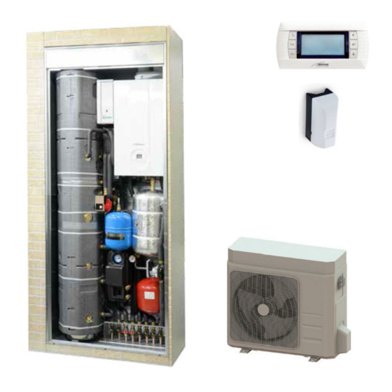
Basic OPEN HYBRID MEM-ECO Structure
Description of the core components forming the system.
Additional Appliances and Devices
Details on optional components like heat pumps and remote controls.
OPERATIONAL MODES AND HEATING
Domestic Hot Water (DHW) Preparation
How the system prepares DHW using solar thermal and heat pump.
Heating System Operation
Management of heating requests by heat pump and boiler.
ADVANCED OPERATIONAL FUNCTIONS
Cooling Functionality and Protection Features
Details on cooling mode, anti-freeze, anti-blocking, and degassing functions.
SYSTEM STRUCTURE AND CONNECTIONS
Component Identification Diagram
Diagram keying the main system components and their identification.
Water Circuit Connections
Diagrams illustrating water connections for the system.
BOILER TECHNICAL SPECIFICATIONS
Boiler Certifications and Performance Data
Technical specs including certifications, performance, efficiency, and electrical data.
Combustion Data
Details on smoke temperature, flow, CO2, and NOx emissions.
GAS AND HEAT PUMP SPECIFICATIONS
Gas System Parameters
Nozzle details, gas consumption, and pressure/temperature limits.
Heat Pump Performance Data
Capacity, power, COP, SEER, and water flow for heat pump models.
EXTERNAL FANS AND HEAT EXCHANGER DATA
External Fans, Heat Exchanger, and Water Circuit
Specifications for external fans, internal heat exchanger, and water circuit.
MAIN WATER CIRCUITS
Base Configuration Water Circuit
Diagram of the basic system water circuit.
High Temperature Kit Water Circuit
Diagram showing the water circuit with the high temperature kit.
SYSTEM WATER CIRCUIT DIAGRAMS
High Temp Kit and Solar Kit Water Circuit
Diagram showing the water circuit with high temp kit and solar kit.
Diagram Component Key
Legend explaining symbols and abbreviations in the water circuit diagrams.
SENSORS AND EXPANSION VESSELS
Sensor Specifications and Data
Details on sensor characteristics and temperature/resistance correlation.
Expansion Vessel Characteristics
Information on expansion vessel capacity and prefilling pressure.
CONTROL AND COMMUNICATION INTERFACES
Operating LED Status and Troubleshooting
Explanation of LED indicators and their troubleshooting.
Mem Remote Control Functions
Overview of the Mem Remote Control buttons, display, and functions.
ELECTRICAL PANEL AND WIRING DIAGRAM
Electrical Panel Component Identification
Diagram and key for electrical panel components.
System Wiring Diagram Overview
Schematic showing electrical connections between components.
DETAILED ELECTRICAL WIRING DIAGRAMS
Boiler and Electrical Panel Wiring
Detailed wiring for boiler terminal board and electrical panel.
Heat Pump and Power Supply Wiring
Wiring for heat pump power supply and connections.
INSTALLATION GUIDELINES
Receiving Product, Dimensions, and Handling
Procedures for receiving, checking dimensions, and handling the appliance.
Installation Room Requirements
Specifications for the installation room, including ventilation and temperature.
BOILER AND WATER SYSTEM INSTALLATION
Boiler Installation in Frame
Steps for positioning and securing the boiler within its frame.
Water System Kit Connections
Guidelines for connecting water system kit components.
WATER CIRCUIT PIPING CONNECTIONS
Boiler and Storage Tank Pipe Connections
Details on connecting pipes for DHW output, gas, and ACS inlet.
Diverter Valve and Heat Pump Pipe Connections
Instructions for connecting pipes to the diverter valve and heat pump.
PUFFER AND SYSTEM PIPE CONNECTIONS
Puffer Installation and Pipe Connections
Steps for fitting the puffer and connecting system pipes.
Low Temperature System Pump Assembly
Instructions for assembling the pump and connecting pipes for the low temp system.
HEAT PUMP INSTALLATION AND PLUMBING
External Heat Pump Installation Guidelines
Recommendations for external heat pump installation, including service gaps.
Heat Pump Plumbing Connections
Requirements for plumbing connections and components for the heat pump.
SMOKE OUTLET AND COMBUSTION AIR INLET
Frame Openings for Ducts
Diagram showing positions and dimensions for duct openings in the frame.
Smoke Duct Safety Warnings
Safety notes on smoke flue, duct materials, and air-tightness.
SMOKE DUCT ACCESSORIES
Coaxial Duct System Accessories
List of accessories for coaxial duct systems.
Split Pipe System Accessories
List of accessories for split pipe systems.
REMOTE CONTROL INSTALLATION
Mem Remote Control Mounting and Connection
Instructions for mounting and connecting the Mem Remote Control.
Duct Extension Length Limitations
Warning on maximum duct extension lengths based on diameter and load loss.
SENSOR POSITIONING AND WIRING
Sensor Placement Guidelines
Instructions for correct positioning of system sensors.
External Sensor Installation and Wiring
Guidance on installing the external sensor and its wiring.
ELECTRICAL CONNECTIONS
Mains Power Connection Requirements
Mandatory requirements for safe connection to the mains network.
Component and Boiler Connections
Details on connecting system components and the boiler to the panel.
SYSTEM FILLING PROCEDURES
Filling the DHW Storage Tank
Steps for filling the domestic hot water storage tank.
System Filling and Initial Setup
Procedure for filling the heating system and initial setup.
AUTOMATIC DEGASSING AND PARAMETER ACCESS
Activating Automatic Degassing Function
Step-by-step guide to activate the automatic degassing function.
Accessing Boiler Parameter Menu
Instructions on how to access the boiler parameters menu.
EMPTYING OPERATIONS AND IMPORTANT NOTES
Emptying DHW Storage Tank
Procedure for draining the domestic hot water storage tank.
Post-Operation Checks and Warnings
Mandatory checks and warnings after draining operations.
COMMISSIONING PROCEDURE
Preliminary Operations and Checks
Essential checks before commissioning the appliance.
Boiler Startup and Self-Calibration
Steps for boiler startup and the automatic self-calibration procedure.
PARAMETER SETTING AND DISPLAY
Accessing and Navigating Parameters
Guide on entering and navigating the parameter menu.
Modifying Parameter Values
Instructions on adjusting and confirming parameter values.
COMPLETE LIST OF PARAMETERS (PART 1)
General Settings Parameters
Parameters for climate control, DHW modes, language, and time.
Generation System Settings Parameters
Parameters for anti-blocking, degassing, filling, and system types.
COMPLETE LIST OF PARAMETERS (PART 2)
Input/Output Configuration Parameters
Parameters for configuring digital/analogue inputs and outputs.
Heating Circuit Parameters
Parameters for low and high temperature heating circuits.
COMPLETE LIST OF PARAMETERS (PART 3)
Cooling Circuit and DHW Settings
Parameters for cooling setpoints and domestic hot water functions.
Energy Settings and Communication Parameters
Parameters for energy costs, photovoltaic system, and Modbus communication.
GENERAL SETTINGS CONFIGURATION
Climate Control Operating Mode Selection
How to set the climate control operating mode.
Domestic Hot Water Operating Mode Selection
Options for selecting the DHW operating mode.
GENERATION SYSTEM SETTINGS
Anti-blocking, Air Venting, and Filling Functions
Configuration of system functions like anti-blocking, air venting, and filling.
Heat Pump Priorities and Solar System Type
Settings for heat pump priorities and solar thermal system type.
SOLAR AND COOLING SETTINGS
Solar Pump Operation and Anti-Freeze
Configuration for solar pump operation, anti-freeze, and cooling functions.
INPUT AND OUTPUT CONFIGURATION
Displaying and Configuring I/O Values
Viewing and configuring analogue/digital input/output values.
HEATING CIRCUIT PARAMETER SETTINGS
Low Temperature Circuit Adjustment Types
Selecting adjustment types for the low temperature circuit.
Low Temperature Circuit Fixed Setpoint
Setting the fixed temperature setpoint for the low temperature circuit.
LOW TEMPERATURE CIRCUIT CURVE ADJUSTMENT
Curve Rotation and Transfer for Mild Temperatures
Adjusting the heating curve for mild external temperatures.
Setpoint Limits and Safety Thermostat
Configuring setpoint limits and the 50°C safety thermostat.
HIGH TEMPERATURE AND COOLING SETTINGS
High Temperature Circuit Setpoint and Priority
Setting setpoints and priority for the high temperature circuit.
Cooling System Setpoint Configuration
Setting cooling system setpoints and humidistat requests.
DOMESTIC HOT WATER (DHW) SETTINGS
DHW Comfort and Reduced Setpoints
Configuring temperature setpoints for DHW comfort and reduced modes.
Anti-Legionella Function and Storage Tank Management
Activating anti-legionella function and managing DHW storage tank.
ENERGY SETTINGS AND PHOTOVOLTAIC FUNCTION
Electrical-Primary Energy Conversion Factor
Setting the factor for converting energy sources to a common unit.
Energy Costs and Photovoltaic System Setup
Inputting energy costs and configuring photovoltaic system.
COMMUNICATION SETTINGS
Modbus Address Configuration
Setting Modbus addresses for boiler and heat pump.
Boiler and Heat Pump Information Display
Viewing operational data for boiler and heat pump.
CIRCULATION PUMP CONTROL
Circulation Pump Settings Mode and Curves
Selecting pump settings mode and characteristic curves.
Pump Functions: Venting, Restart, and Locking
Using pump functions like venting, restart, and keypad locking.
MAINTENANCE AND ALARMS
Annual Adjustments and Anode Check
Recommendations for annual maintenance and anode inspection.
Alarm Codes and Descriptions
List of alarm codes, their causes, and solutions.
ALARM HANDLING AND TROUBLESHOOTING
Specific Alarm Causes and Solutions
Detailed solutions for various alarms like thermostat, pressure, and Modbus faults.
Remote Control Unit Faults Troubleshooting
Troubleshooting steps for remote control unit power and connectivity issues.
PUMP AND ALARM LOG TROUBLESHOOTING
Pump Fault Indicators and Solutions
Troubleshooting pump status based on LED color and fault type.
Accessing and Interpreting the Alarm Log
How to display and scroll through the alarm log.
APPLICATION DIAGRAMS - HEATING ONLY
Diagram 1a: Radiating Panel Heating Only
Wiring diagram for a system with radiating panels for heating only.
APPLICATION DIAGRAMS - HEATING AND COOLING
Diagram 2a: Radiating Panel Heating & Fan Convectors Cooling/Dehumidifying
Wiring for radiating panels (heating) and fan convectors (cooling/dehumidifying).
APPLICATION DIAGRAMS - HEATING AND COOLING (CONT.)
Diagram 2b: Radiating Panel Heating & Fan Convectors Cooling/Dehumidifying (with Diverter Valve)
Wiring for panels (heating) and fan convectors (cooling/dehumidifying) using a diverter valve.
APPLICATION DIAGRAMS - FAN CONVECTORS
Diagram 3a: Fan Convectors Heating + Cooling/Dehumidifying
Wiring diagram for systems using fan convectors for heating, cooling, and dehumidifying.
APPLICATION DIAGRAMS - RADIATING PANELS WITH DEHUMIDIFIERS
Diagram 4a: Radiating Panel Heating+Cooling with Electrical Dehumidifiers
Wiring for panels (heating/cooling) with electrical dehumidifiers.
APPLICATION DIAGRAMS - RADIATING PANELS WITH HYDRONIC DEHUMIDIFIERS
Diagram 4b: Radiating Panel Heating+Cooling with Hydronic Dehumidifiers
Wiring for panels (heating/cooling) with hydronic dehumidifiers.
APPLICATION DIAGRAMS - PANELS AND FAN CONVECTORS
Diagram 4c: Radiating Panel Heating+Cooling with Fan Convectors Cooling/Dehumidifying
Wiring for panels (heating/cooling) and fan convectors (cooling/dehumidifying).
APPLICATION DIAGRAM - HIGH TEMPERATURE CIRCUIT KIT
High Temperature Circuit Wiring
Diagram illustrating the wiring for a high temperature circuit kit.
ANNEXES - BOILER PRODUCT BOARD (MODELS 25)
Product Board Data for 25-6A to 25-12 Models
Technical product data for 25-6A through 25-12 models.
ANNEXES - BOILER PRODUCT BOARD (MODELS 30)
Product Board Data for 30-6 to 30-12 Models
Technical product data for 30-6 through 30-12 models.
ANNEXES - BOILER PRODUCT BOARD (MODELS 35)
Product Board Data for 35-6 to 35-12 Models
Technical product data for 35-6 through 35-12 models.
ANNEXES - BOILER PRODUCT BOARD (S MODELS - PART 1)
Product Board Data for 25-6 S to 25-10 S Models
Technical product data for 25-6 S through 25-10 S models.
ANNEXES - BOILER PRODUCT BOARD (S MODELS - PART 2)
Product Board Data for 30-6 S to 30-12 S Models
Technical product data for 30-6 S through 30-12 S models.
ANNEXES - BOILER PRODUCT BOARD (S MODELS - PART 3)
Product Board Data for 35-6 S to 35-12 S Models
Technical product data for 35-6 S through 35-12 S models.
DESCRIPTION OF THE APPLIANCE
1.1 Characteristics
Overview of the OPEN HYBRID MEM ECO boilers' design and features.
1.2 Check and Safety Devices
List of integrated safety devices like thermostats and sensors.
TECHNICAL DATA PLATE INFORMATION
1.3.1 Technical Data Plate Details
Information found on the technical data plate.
SYSTEM STRUCTURE AND COMPONENTS
1.4 Structure - Component Identification
Diagram and key identifying the main internal boiler components.
MAIN WATER CIRCUIT AND SENSORS
1.5 Main Water Circuit Diagram
Schematic showing primary water connections within the boiler.
1.6 Sensor Specifications and Data
Details on sensor characteristics and temperature/resistance correlation.
CIRCULATION PUMP PERFORMANCE
1.8 Circulation Pump Flow-Head Curve
Graph showing the performance curve for the circulation pump.
CONTROL PANEL OPERATION
1.9 Control Panel - Functional Buttons
Explanation of the control panel's buttons and their functions.
1.9 Control Panel - Display Symbols
Guide to understanding the symbols and indicators on the control panel.
WIRING DIAGRAMS AND ELECTRICAL CONNECTIONS
1.10 Wiring Diagram Overview
Schematic showing electrical connections between components.
Electrical Connection Safety Precautions
Safety notes for electrical connections, including earthing.
INSTALLATION GUIDELINES
2.1 Receiving Product, Dimensions, and Handling
Procedures for receiving, checking dimensions, and handling the appliance.
2.4 Installation Room Requirements
Specifications for the installation room, including ventilation and temperature.
SYSTEM PREPARATION FOR INSTALLATION
2.5 New Installation or Replacement Considerations
Checks for installing on old systems or replacing generators.
2.7 Water System Treatment Recommendations
Advice on water quality, filters, and chemical treatments.
PLUMBING AND GAS CONNECTIONS
2.8 Plumbing Connections Layout
Diagram and dimensions for plumbing connections.
2.10 Gas Supply Requirements
Instructions for connecting the gas supply.
SMOKE OUTLET AND COMBUSTION AIR INLET
2.11 Permitted Outlets and Configurations
Overview of permitted smoke outlet and air inlet configurations.
Smoke Duct Safety Warnings
Safety notes on smoke flue, duct materials, and air-tightness.
SMOKE DUCT ACCESSORIES AND LOSS CALCULATIONS
Coaxial and Split Pipe System Accessories
Lists of accessories for coaxial and split pipe systems.
Load Loss Calculation Guidelines
Instructions for calculating load loss of duct accessories.
SMOKE DUCT LOAD LOSS DATA
Load Loss Data for Ø 60mm and Ø 80mm Ducts
Tables detailing load loss for accessories used with Ø 60mm and Ø 80mm ducts.
ELECTRICAL CONNECTIONS AND REFILLING
2.12 Electrical Connections Requirements
Mandatory requirements for electrical connections.
2.13.1 Refill Operations
Step-by-step guide for refilling the DHW and heating circuits.
SYSTEM REFILLING AND EMPTYING
Refilling Procedure Notes and Panel Refitting
Notes on air removal during refilling and refitting the front panel.
2.13.2 Emptying Operations
Procedure for emptying the DHW circuit and boiler.
COMMISSIONING PROCEDURE
3.1 Preliminary Operations and Checks
Essential checks before commissioning the appliance.
3.2 Boiler Startup and Self-Calibration
Steps for boiler startup and the automatic self-calibration procedure.
PARAMETER SETTING AND DISPLAY
3.3 Parameter Setting Interface
Guide to navigating and setting parameters on the display.
3.4 List of System Parameters (Part 1)
Table listing system parameters, ranges, and defaults.
SYSTEM PARAMETER LIST (PART 2)
3.4 List of System Parameters (Part 2)
Continuation of parameter list for DHW and heating.
Malfunction/Fault Alarm Codes
List of fault codes, their causes, and solutions.
OPERATING DATA AND COUNTERS
3.5 Display of Operating Data
Viewing system operating data like temperatures and pressures.
3.5 Counters and Activated Alarms
Accessing system counters and the list of activated alarms.
CHIMNEY SWEEPER FUNCTION
3.6.1 Chimney Sweeper Function Procedure
Step-by-step guide to use the chimney sweeper function for checks.
DHW COMFORT AND GAS CONVERSION
3.7 DHW Comfort Function (Preheating)
Activating and configuring the DHW comfort function.
3.8 Gas Conversion Procedure
Instructions for converting the boiler between different gas types.
MAINTENANCE PROCEDURES
4.1 Adjustments and Cleaning Recommendations
Guidelines for annual adjustments and cleaning the cladding.
4.3.1 Removing Components for Cleaning
Steps for removing internal components for cleaning.
INTERNAL CLEANING AND CHECKS
4.3.2 Burner and Combustion Chamber Cleaning
Procedure for cleaning the burner and combustion chamber.
4.4 Checks: Smoke Duct and Expansion Vessel
Recommended checks for smoke duct integrity and expansion vessel pressure.
UNSCHEDULED MAINTENANCE AND FAULT CODES
4.5 Replacing Electronic Board and Parameter Setup
Instructions for setting parameters when replacing the electronic board.
Malfunction/Fault Alarm Codes
Comprehensive list of malfunction codes, causes, and solutions.
FAULT CODES AND MAINTENANCE REQUEST
Specific Fault Code Solutions
Troubleshooting solutions for various fault codes.
4.6.1 Maintenance Request Symbol
Indication of the symbol that appears when maintenance is due.
ANNEXES - BOILER PRODUCT BOARD (MODELS 25)
Product Board Data for 25-6A to 25-12 Models
Technical product data for 25-6A through 25-12 models.
ANNEXES - BOILER PRODUCT BOARD (MODELS 30)
Product Board Data for 30-6 to 30-12 Models
Technical product data for 30-6 through 30-12 models.
ANNEXES - BOILER PRODUCT BOARD (MODELS 35)
Product Board Data for 35-6 to 35-12 Models
Technical product data for 35-6 through 35-12 models.
Need help?
Do you have a question about the OPEN HYBRID MEM-ECO 25-12 and is the answer not in the manual?
Questions and answers