
Related Manuals for Chroma 6415


Summarization of Contents
SAFETY SUMMARY
SAFETY SYMBOLS
Explains the meaning of various safety symbols used in the manual and on the instrument.
1. An Overview of the Products
1.1 Introduction
Introduces the Chroma 6400 series AC power sources and their capabilities.
1.2 The Features
Details the configuration and input/output features of the Chroma 6400 series AC sources.
1.3 Specifications
Lists the operational specifications for Chroma 6430/6420/6415 models, including output ratings and input ratings.
1.4 Operational Panels
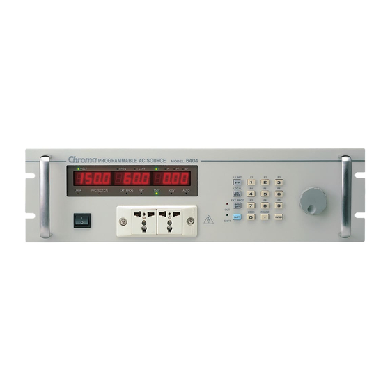
1.4.1 Front Panel
Describes the front panel layout, including display areas and control buttons, of the AC source.
1.4.2 Rear Panel
Details the rear panel connectors and ports for input, output, and communication interfaces.
2. Installation
2.1 Inspection
Provides instructions for inspecting the instrument for damage after unpacking.
2.2 Preparation for Use
Outlines essential preparation steps for operating the instrument, including environmental and air circulation requirements.
2.3 Requirements of Input Power
Specifies the necessary input voltage, frequency, and current ratings for the AC source.
2.4 Output Connection
Explains how to safely connect the output power terminals to the load with appropriate wiring.
2.5 Remote Sense Connection
Details the procedure for connecting remote sensing to improve voltage regulation at the load.
2.6 Power-on Procedures
Guides users through the step-by-step process of powering on the instrument and its self-test sequence.
2.7 I/O Connectors (Optional)
Describes the optional GPIB and RS-232C connectors for external control and communication.
3. Local Operation
3.1 Introduction
Introduces local and remote operational modes for configuring and controlling the AC source.
3.2 Setup
Covers essential configuration settings such as GPIB address, RS-232C baud rate, OVP, and system tests.
3.2.1 GPIB Address
Instructions for setting the GPIB address required for remote operational mode.
3.2.2 RS-232C
Details on configuring RS-232C communication protocol, including baud rate and parity.
3.2.3 Over Voltage Protection
Explains how to set the upper limit for output voltage to protect connected devices.
3.2.4 Sound (ON/OFF)
Describes how to enable or disable the beep sound feature during programming.
3.2.5 System Test
Procedure for checking if the output power meets the instrument's specifications.
3.2.6 Power on Status
Guides setting the initial output values for voltage, frequency, and range upon power-on.
3.2.7 Remote Sense (ON/OFF)
Explains how to enable or disable the remote sensing feature for output voltage.
3.3 Output Setting and Execution
Details on setting output parameters like current limit, voltage range, and frequency.
3.3.1 I Limit
Describes setting the output current limit to protect loading devices from overcurrent.
3.3.2 Range
Instructions for selecting the output voltage range (150V, 300V, or AUTO).
3.3.3 Output V and F
Demonstrates setting specific output voltage and frequency values.
3.4 Save and Recall
Explains how to save and recall frequently used settings using memory channels.
3.5 Data Lock
Procedure to lock the front panel keypad to prevent accidental changes to settings.
3.6 Ext Prog
Details using an external DC voltage for linear control of output Vrms.
3.7 Measurement
Describes how to measure actual performances like V, F, I, P, PF, and CF of a connected load.
3.7.1 Select the Items of Measurement
Instructions on selecting specific measurement items (I, P, PF, CF) for read-back.
3.7.2 Functions of Measurement
Explains the six measurement functions: Voltage, Frequency, Current, Power, Crest Factor, and Power Factor.
3.8 Local Operation
Guides returning the instrument to local operation mode from remote control.
3.9 Protection
Details the instrument's protection features against voltage, current, power, and temperature issues.
4. Theories of Operation
4.1 General Information
Provides a general overview of the AC power source, its components, and their functions.
4.2 Description of Overall System
Presents a block diagram and explanation of the instrument's overall system architecture and signal flow.
4.3 AC/DC Power Stage Converter
Explains the functionality of the switch-mode PWM converter used for AC/DC power conversion.
4.4 DC/DC Power Stage Converter
Details the DC/DC power stage converter responsible for generating isolated DC power outputs.
4.5 DC/AC Inverter
Describes the DC/AC inverter system, including its PWM technology and components.
4.6 CPU
Explains the role of the CPU (80C188) in controlling the instrument's operations and communication.
4.7 Measurement
Describes how the measurement circuits monitor and process voltage, current, and power data.
4.8 Sine Wave Generator
Explains the sine wave generator's function in producing sinusoidal waveforms.
4.9 Keyboard and Display
Details the interface provided by the keyboard and the seven-segment LED display.
4.10 GPIB/RS-232C/External Reference
Covers remote control via GPIB/RS-232C and the use of external references for voltage control.
5. Self-Test and Troubleshooting
5.1 General Information
Provides guidance on performing self-tests and troubleshooting common issues with the AC source.
5.2 Self-Test Routine
Describes the instrument's built-in test program for verifying functionality and performing adjustments.
5.3 Troubleshooting
Lists common operational problems, their probable causes, and suggested solutions.
6. Remote Operation
6.1 General Information
Overview of controlling the AC source remotely using GPIB or RS-232C interfaces.
6.2 The GPIB Capability of the AC Source
Details the GPIB interface capabilities, including talker/listener functions and service requests.
6.3 Introduction to Programming
Explains programming conventions, ASCII codes, and data transfer for remote control.
6.3.1 Conventions
Defines standard programming conventions, including parameter abbreviations and optional syntax.
6.3.2 Numerical Data Formats
Describes the various numerical data formats accepted by the instrument for programming.
6.3.3 Boolean Data Format
Explains the format for boolean parameters like ON/OFF or 1/0.
6.3.4 Character Data Format
Details the formats for character strings returned by query commands.
6.3.5 Basic Definition
Defines key programming terms like command tree structure, headers, and message units.
6.4 Traversal of the Command Tree
Explains how to navigate and construct commands using the hierarchical command tree structure.
6.5 Execution Order
Describes the sequence of execution for program messages, including coupled commands.
6.6 The Commands of the AC Source
Provides a comprehensive list and description of the commands available for controlling the AC source.
6.6.1 Command Tree Table
Presents a hierarchical table outlining the structure of the instrument's commands.
6.6.2 Command Dictionary
Provides detailed explanations for specific programming commands and queries.
OUTPut
Commands to enable or disable the AC source output and query its state.
OUTPut:PROTection:CLEar
Command to clear any latched protection conditions that have disabled the output.
CURRent
Commands for setting and querying the output current limit.
FREQuency
Commands for setting and querying the output frequency.
VOLTage
Commands for setting and querying the output voltage amplitude.
VOLTage:EPRogram
Commands to enable or disable external program mode for voltage control.
VOLTage:LIMit
Commands to set the maximum bounds for the AC rms output voltage.
VOLTage:RANGE
Commands to select the output voltage range (150V or 300V).
VOLTage:RANGE:AUTO
Commands to enable or disable the automatic output voltage range selection.
STATus:PRESet
Command to preset the status registers for Questionable and Operation status.
STATus:OPERation?
Query to retrieve the content of the Operation Event Register.
STATus:OPERation:CONDition?
Query to retrieve the content of the Operation Condition Register.
STATus:OPERation:ENABle
Command to set the enable mask for the Operation Event Register.
STATus:QUEStionable?
Query to retrieve the content of the Questionable Event Register.
STATus:QUEStionable:CONDition?
Query to retrieve the content of the Questionable Condition Register.
STATus:QUEStionable:ENABle
Command to set the enable mask for the Questionable Event Register.
STATus:QUEStionable:NTRansition
Command to set the Questionable Negative Transition (NTR) register.
STATus:QUEStionable:PTRansition
Command to set the Questionable Positive Transition (PTR) register.
SYSTem:ERRor?
Query to retrieve error messages from the instrument's error queue.
SYSTem:LOCal
Command to set the instrument to local control mode via RS-232C.
SYSTem:REMote
Command to set the instrument to remote control mode via RS-232C.
SYSTem:RWLock
Command to set the instrument to remote-lockout mode via RS-232C.
*CLS, Clear Status Command
Clears all status registers and the error queue in the instrument.
*ESE, Standard Event Status Enable Command
Command to set the enable mask for the Standard Event Status Register.
*ESR?, Standard Event Status Register Query
Query to retrieve the content of the Standard Event Status Register.
*IDN?, Identification Query
Query to retrieve the instrument's manufacturer, model, serial number, and firmware level.
*OPC, Operation Complete Command
Command to set the OPC bit when all pending operations are completed.
*OPC?,Operation Complete Query
Query to confirm completion of all pending operations.
*RST, Reset Command
Resets the AC source to its default operational states and settings.
*SRE, Service Request Enable Command
Command to configure which events trigger a service request.
*STB?, Read Status Byte Query
Query to retrieve the status byte register, indicating operational states.
*TST?, Self-Test Query
Query to initiate and report the results of an internal self-test.
*WAI, Wait-to-continue
Command to pause execution until all pending operations are finished.
6.7 Status Reporting
Explains the status data structure and reporting mechanisms based on IEEE 488.2.
6.7.1 Questionable Status
Details signals and registers that indicate abnormal operation and potential issues.
6.7.2 Standard Event Status
Lists the conditions that are latched by the Standard Event Status Register.
6.7.3 Status Byte Register
Explains the summary-messages from other status registers within the Status Byte Register.
6.8 Error Messages
Lists common error codes, their descriptions, and potential causes encountered during operation.
Need help?
Do you have a question about the 6415 and is the answer not in the manual?
Questions and answers