Table of Contents
Advertisement
Advertisement
Table of Contents

Related Manuals for Chroma 6408


Summarization of Contents
Product Overview
Introduction
Overview of the Chroma 6404/6408 AC Power Source and manual content.
Key Features
Highlights the main capabilities and configuration options of the AC source.
Specifications
Lists the detailed operational specifications for the 6404/6408 models.
Operational Panels
Describes the front and rear panels of the instrument.
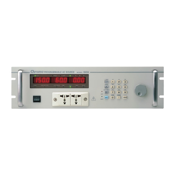
Front Panel
Detailed description of the front panel controls and indicators.
Rear Panel
Details of connectors and ports on the rear panel.
Installation
Inspection
Procedures for inspecting the instrument upon receipt for shipping damage.
Preparation for Use
Steps for preparing the instrument for initial operation and installation.
Input Power Requirements
Specifies voltage, frequency, and current requirements for power input.
Local Operation
Introduction
Explains operation using the front panel keypad in local mode.
Set up
Configuration settings for GPIB, RS-232, OVP, sound, and system test.
Output Setting & Execution
Procedures for setting output voltage, frequency, and current limits.
I limit
Setting the maximum output current limit for device protection.
Range
Selecting the output voltage range (150V, 300V, AUTO).
Output V & F
Setting output voltage and frequency values.
Save & Recall
Saving and recalling frequently used settings to/from memory channels.
Data Lock
Locking the front panel keypad to prevent accidental changes.
Ext Prog
Enabling external control of output voltage via DC reference.
Measurement
Measuring output performance parameters like V, F, I, P, PF, CF.
Select Measurement Items
Choosing which measurement items to display.
Measurement Functions
Explains available measurement functions (V, F, I, P, PF, CF).
Local
Returning from remote mode to front panel operation.
Protection
Overview of protection mechanisms like UVP, OCP, OTP, and FAN failure.
Theory of Operation
General
Overview of the instrument's main boards and components.
Overall System Description
High-level overview of the instrument's system block diagram.
CPU
Description of the CPU (A board) and its function.
Measurement & Sine wave Generator (B Board)
Function of the B board for measurement and sine wave generation.
Keyboard & Display
Description of the K board (keyboard) and display interface.
GPIB/RS-232C/External reference
Details on communication interfaces and external reference input.
Self-test and Troubleshooting
General
Introduction to self-test and troubleshooting procedures.
Self-test Routine
Information on the built-in self-test program for verifying unit functionality.
Troubleshooting
Common problems, reasons, and suggested solutions for instrument issues.
Remote Operation
General Information
Introduction to remote control capabilities via GPIB or RS-232.
GPIB Capability of the AC Source
Overview of GPIB interface capabilities and functions.
Introduction to Programming
General information on programming commands, syntax, and conventions.
Numerical Data Formats
Formats accepted for numeric data input in commands.
Boolean Data Format
Format for boolean parameters (ON/OFF) in commands.
Character Data Format
Formats for character string responses from the instrument.
Basic Definition
Definitions of programming terms like headers, messages, and terminators.
The AC Source Commands
Introduction to the command structure and available commands for remote control.
Command Dictionary
Detailed descriptions of specific commands, their syntax, and parameters.
Need help?
Do you have a question about the 6408 and is the answer not in the manual?
Questions and answers