Table of Contents
Advertisement
Quick Links
Advertisement
Table of Contents
Troubleshooting

Related Manuals for Chroma 61705


Summary of Contents for Chroma 61705
- Page 3 Programmable AC Source 61705 User’s Manual Version 1.6 November 2015...
- Page 4 The information in this document is subject to change without notice. Chroma ATE INC. makes no warranty of any kind with regard to this manual, including, but not limited to, the implied warranties of merchantability and fitness for a particular purpose.
- Page 5 All of Chroma’s instruments are warranted against defects in material and workmanship for a period of one year from date of shipment. Chroma agrees to repair or replace any assembly or component found to be defective, under normal use during this period. Chroma’s obligation under this warranty is limited solely to repairing any such instrument, which in Chroma’s sole...
- Page 6 “” indicates that the level of the specified chemical substance exceeds the threshold level specified in the standards of SJ/T-11363-2006 and EU 2005/618/EC. Chroma is not fully transitioned to lead-free solder assembly at this moment; however, most of the components used are RoHS compliant.
- Page 7 Material Contents Declaration Chroma provides material contents declaration for RoHS compliant products as below: Hazardous Substances Lead Mercury Cadmium Hexavalent Polybrominated Polybromodiphenyl Part Name Chromium Biphenyls Ethers PBDE PCBA CHASSIS ACCESSORY PACKAGE “O” indicates that the level of the specified chemical substance is less than the threshold level specified in the standards of SJ/T-11363-2006 and EU 2005/618/EC.
- Page 9 Failure to comply with these precautions or specific WARNINGS given elsewhere in this manual will violate safety standards of design, manufacture, and intended use of the instrument. Chroma assumes no liability for the customer’s failure to comply with these requirements.
- Page 10 Safety Symbols DANGER – High voltage. Explanation: To avoid injury, death of personnel, or damage to the instrument, the operator must refer to the explanation in the instruction manual. High temperature: This symbol indicates the temperature is hazardous to human beings. Do not touch it to avoid any personal injury.
- Page 11 Version Revised Sections Oct. 2003 1.0 Complete this manual Aug. 2005 1.1 Change the address and phone no. of Chroma ATE Inc. Aug. 2007 1.2 “Material Contents Declaration”. “Notice” in the section of “OUTPUT RELAY”. Modify the tables and figures in the section of “Appendix B: Built-in Waveforms”.
-
Page 13: Table Of Contents
Programmable AC Source 61705 User’s Manual Table of Contents General Information ....................1-1 Introduction ......................1-1 Key Features ....................... 1-1 Specifications ....................... 1-1 Names of Parts ....................1-4 1.4.1 The Front Panel ................... 1-4 1.4.2 The Rear Panel .................... 1-6 1.4.3... - Page 14 Programmable AC Source 61705 User’s Manual 4.2.1 Output Voltage and Voltage Measurement Calibration ......... 4-3 4.2.2 Current Measurement Calibration ..............4-5 4.2.3 Phase Angle Calibration ................4-6 Application........................ 5-1 General ........................ 5-1 List Mode (Optional Function) ................5-1 Pulse Mode (Optional Function) ................5-5 Step Mode (Optional Function) ................
-
Page 15: General Information
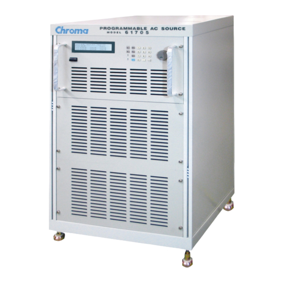
General Information Introduction The Chroma AC Source 61705 is a high efficiency, 3-phase AC power source which provides sine wave output with low distortion, and accurate measurement of power. The DSP microprocessor generates accurate, stable output voltage and frequency. The PWM design of power stage allows for full volt-ampere into loads. - Page 16 Programmable AC Source 61705 User’s Manual Model 61705 AC OUTPUT RATING Max. Power 12000 VA Power Per Phase 4K VA Voltage Range 150V / 300V Output Voltage 0~150V/0~300V, 0~140V/0~280V@>1000Hz Accuracy 0.2%+0.2%F.S. Resoluction 0.1 V Distortion 0.3% @50/60Hz 1.5%15- 1.2KHz Line Rregulatoin 0.1%...
- Page 17 General Information 0 °C to 40 °C Operation -40 °C to 85 °C Storage Humidity 30 % to 90 % Safety & EMC Note 1. Maximum distortion is tested under output 125VAC (150V RANGE) and 250VAC (300V RANGE) with maximum current to linear load. 2.
-
Page 18: Names Of Parts
Programmable AC Source 61705 User’s Manual Names of Parts 1.4.1 The Front Panel Figure 1-1 The Front Panel... - Page 19 General Information Item Symbol Description Display: The LCD displays the configuration, output setup, and measurement results. Indicator LED: “OUT” and “SHIFT”, for showing activation of output and shift mode, are available and located on the keypad area next to the corresponding keys. Cursor moving keys: These two keys move the cursor to ...
-
Page 20: The Rear Panel
Programmable AC Source 61705 User’s Manual 1.4.2 The Rear Panel Figure 1-2-2 The Rear Panel Figure 1-2 The Rear Panel Table 1-2 The Description of the Rear Panel... - Page 21 General Information Item Name Description Label The label includes model number, serial number of the AC Source. The BNC connector inputs control waveform amplitude from Ext. Ref. external analog signal. (This function is reserved now.) The 9-pin, D-type female connector transfers control commands RS-232C to and from the remote PC for remote operation.
-
Page 22: The Rear Panel (With Usb & Ethernet)
Programmable AC Source 61705 User’s Manual 1.4.3 The Rear Panel (with USB & Ethernet) Table 1-2 Description of Rear Panel Item Name Description Ext. Ref. A BNC connector to control waveform amplitude via external analog (simulated). Connecting AC source and PC for communication. -
Page 23: Installation
If any damage is found, please file a claim with the carrier immediately. Do not return the instrument to the factory without obtaining prior RMA acceptance from Chroma. Preparation for Use In the beginning, the instrument must be connected with an appropriate AC line input. Then, since fans intelligently cool it, it must be installed in sufficient space for circulation of air. - Page 24 Programmable AC Source 61705 User’s Manual Slip the safety cover over the ac input terminal strip, and secure the cover with four screws. WARNING To protect the operators, the wire connected to the GND terminal must be connected to the earth. Under no circumstances shall this AC Source be operated without an adequate ground connection.
-
Page 25: Output Connection
Installation Figure 2-3 Terminal Safety Cover Output Connection The output terminal block is located in the rear of the AC Source. Load connecting to the “Φ1/L”, “Φ2/L”, “Φ3/L”, “N” and “G” are done at the output terminals. To meet the safety requirements, the safety cover must be fastened. -
Page 26: Remote Sense Connection
Programmable AC Source 61705 User’s Manual Φ1/L Φ2/L Φ3/L N PE (Earth Ground) Figure 2-4 Output Terminal Connection Remote Sense Connection The remote sense function of the AC Source monitors the voltage at the load instead at the output terminal of the AC Source. It ensures the delivery of accurate voltage as programmed at the load by automatically compensating the output voltage drop over the connecting cable. -
Page 27: Power-On Procedures
Installation Figure 2-5 Output & Remote Sense Connection Power-On Procedures WARNING Before turning on the instrument, all protective earth terminals, extension cords, and devices connected to the instrument must be connected to a protective earth ground. Any interruption of the protective earth grounding will cause a potential shock hazard that could result in personal injury. - Page 28 Programmable AC Source 61705 User’s Manual 2. VERSION QUERY WAVEFORM1 1.02 PANEL 1.02 WAVEFORM2 1.02 REMOTE 1.05 WAVEFORM3 1.02 If any failure is detected on a certain item, an “ERROR CODE” will be shown at the right side of that item. The error messages and trouble-shooting are shown on section 6.2 in this manual.
-
Page 29: I/O Connectors (Option)
Installation I/O Connectors (Option) Figure 2-6 Option Board This option board is for remote control interface: GPIB and RS-232. Figure 2-7 Option Board (with USB and Ethernet) -
Page 31: Local Operation
Local Operation Local Operation Introduction The AC Source can be configured to operate in local or remote mode. The operation in remote mode through a remote GPIB controller or RS-232C is described in Chapter 8. In this section the operation in local mode via keypad on the front panel for data entry and test is described. - Page 32 Programmable AC Source 61705 User’s Manual In CHOICE PAGE, users can press numeric key then to choose the functional lists. ENTER After entering each functional list, press , to move the cursor to destination. If number expresses the settings, users can use numeric and decimal keys or RPG to set the value, then press to confirm.
- Page 33 Local Operation COUNT, TRIG, BASE, COUPLE 5. LIST SEQ, DEGREE Vs, Fs, DCs (start) Ve, Fe, DCe (end) WAVE, TIME/CYCLE 6. PULSE COUNT Vac, F, Vdc DUTY, PERIOD TRIG, WAVE, DEGREE 7. STEP CO COUNT, DWELL Vac, F, Vdc dV, dF, dDC TRIG, WAVE, DEGREE 8.
-
Page 34: Main Page (Output Setting And Measurement)
Programmable AC Source 61705 User’s Manual MAIN PAGE (Output Setting and Measurement) When users turn on the AC Source, the display shows the MAIN PAGE after self-tests. The upper line of display shows the output settings. The state of default output settings can be set on POWER ON STATUS in CONF functional list (see 3.6.4). -
Page 35: Choice Page (Functional List Choice)
Local Operation The definitions of measurement parameters are: : It is the measurement readings of total Power in Watts. : It is the measurement readings of Voltage in Volts. (True RMS measurement) : It is the measurement readings of Current in Amperes. (True RMS measurement) Freq : It is the output frequency in Hertz. -
Page 36: Range
Programmable AC Source 61705 User’s Manual RANGE = 150V_ [ SETUP ] Vac LIMIT = 300 Vdc LMT (+) = 424.2 Vdc LMT (-) = 0.0 I LIMIT (A) = 0.0 DELAY (s) = 0.0 , then to change to next page. -
Page 37: Vdc Limit (+), Vdc Limit
Local Operation 2. Press then press ENTER to change the value to “120.0”. Vac LIMIT(A) = 120.0 The setting of Vac LIMIT is not restricted by RANGE, but the Vac on MAIN PAGE is restricted by RANGE. For example, in 150V RANGE, although Vac LIMIT= 200V, the largest value of Vac setting is 150V. -
Page 38: Output Relay
Programmable AC Source 61705 User’s Manual 1. Move the cursor to the command line of “I LIMIT(A) = ”. I LIMIT(A) = 0.00_ DELAY(S) = 0.0 3. Press , then press to change I LIMIT(A) = 4_ DELAY(S) = 0.0 ENTER the value to “4.00”... -
Page 39: Datalock
Local Operation 2. Turn the RPG to change the option from ON to OFF, then press Buzzer = OFF ENTER 3.5.7 DATALOCK The AC Source allows users to lock data entries, so the pre-defined parameters can be protected from being modified by unauthorized personnel. Users can set DATALOCK on SETUP functional list (see 3.5). - Page 40 Programmable AC Source 61705 User’s Manual PAGE CHOICE = 2_ 1. SETUP 2.CONF 3.OUTPUT 4. MANUAL CALI 5. LIST 6. PULSE 7. STEP 8. INTERHAR REMOTE INHIBIT= OFF [ CONF ] GPIB ADD= 30 BAUD= 19200 WAVEA[Φ1]= SINE WAVEB[Φ1]= SINE...
-
Page 41: Remote Inhibit
Local Operation 3.6.1 REMOTE INHIBIT The output of the AC Source can be inhibited by the external control or by manual trigger. The remote inhibit signal is received from 9-pin female connector on the rear panel (see Appendix A). Users can set REMOTE INHIBIT on CONF functional list (see 3.6). There are three states for remote inhibit: OFF, LIVE, and TRIG. -
Page 42: Gpib Address, Rs-232C
Programmable AC Source 61705 User’s Manual THD to 10%. MODE = THD PER = 10.0 % 1. The clipped sine is programmed by “AMPlitude” or “Total Harmonic Distortion”. Programming ranges from 0 to 100% for amplitude (100%: no clipped sine), and from 0 to 43% for THD (0%: no distortion). -
Page 43: Power On Status
Local Operation 3.6.4 POWER ON STATUS The AC Source allows users to set the output state when the power is switched on. Users can set POWER ON STATUS on CONF functional list (see 3.6). After setting, users should save them before powering off (see 3.8.2). Users also can pre-set voltage of each phase individually if V_SET = INDIVIDUAL (see 3.7.1). -
Page 44: V_Set
Programmable AC Source 61705 User’s Manual , then to change to next page. Press SHIFT [OUTP] Phase 1-2 = 120.0 Phase 1-3 = 240.0 Vs (V/ms) = 0.000 DCs (V/ms) = 0.000 3.7.1 V_SET There are two AC Source output setting modes: ALL and INDIVIDUAL. Users can set V_SET on OUTPUT functional list (see 3.7) to fit the application. -
Page 45: Output Degree
Local Operation 3.7.2 Output Degree The AC Source can control the transition angle of the waveform when it is out or quits. Users can set DEG ON and DEG OFF to achieve it in OUTPUT functional list (see 3.7.) The procedures for setting output phase angle DEGREE ON = 90 and OFF=180 are described as below: 1. -
Page 46: Slew Rate Of Output Transient
Programmable AC Source 61705 User’s Manual 61700 can program the phase angle 0~360°, not fix to 120° only. Users can set PHASE 1-2 and PHASE 1-3 to achieve it in OUTPUT functional list (see 3.7). The parameter of PHASE 1-2 means the phase angle between Phase 1 (Φ1/L) and Phase 2 (Φ2/L). -
Page 47: Save And Recall
Local Operation Save and Recall The AC Source offers two modes for the user to save and recall output setting or system data. They are described in 3.8.1 and 3.8.2. 3.8.1 Save and Recall Output Setting The AC Source offers nine channels for users to save a set of frequently used Vac, F, Vdc, and to recall them for future use. -
Page 48: Save And Recall System Data
Programmable AC Source 61705 User’s Manual Conflicting with RANGE or V LIMIT Press <ENTER> key to Exit 1. The function to save and recall output settings is for MAIN PAGE settings only. Other parameters are ignored. 2. If V_SET=ALL (see 3.7.1), the recall settings for MAIN PAGE are defined to Vac1, Vdc1. -
Page 49: Protection
Local Operation Recall parameters of Group ( 1 - 3 ) : 1_ Press to choose a group to recall, then press to confirm. Then, the ENTER display will return to CHOICE PAGE after the data is loaded. The AC Source provides three memory groups: 1, 2, and 3. The memory group 1 keeps the power-on defaults. -
Page 51: Calibration
Calibration Calibration Introduction The AC Source built a simple way to calibrate the 3-phase output and measurement accuracy without opening the cover. Users can do it for each phase following the procedures step by step. A voltage meter, current meter, suitable load and +5V DC Source are needed during calibration. - Page 52 Programmable AC Source 61705 User’s Manual PAGE CHOICE = 4_ 1. SETUP 2.CONF 3.OUTPUT 4. MANUAL CALI 5. LIST 6. PULSE 7. STEP 8. INTERHAR Enter Password : _ ( You can get password in user's manual ! ) Enter Password : * * * * ( You can get password in user's manual ! ) 1.
-
Page 53: Output Voltage And Voltage Measurement Calibration
Calibration 4.2.1 Output Voltage and Voltage Measurement Calibration On CALIBRATION CHOICE page, press to do the output voltage and voltage ENTER measurement calibration. CALIBRATION CHOICE = 1 1. V OUT AND MEAS. 2. I MEAS. Please Remove Load Before Calibrating Press <ENTER>... - Page 54 Programmable AC Source 61705 User’s Manual seconds then press , then set Vac = 0.00 and Vdc = 0.00. ENTER The AC Source calibration steps can be done individually, but it is suggested to follow the calibration procedure step by step (step A, step B ...).
-
Page 55: Current Measurement Calibration
12.5VAC. Users should apply suitable load to output and make the output current measured by current meter (or power analyzer) for about 1.6A (for 61705). The different model shows different current value in display. If the output current is ok after applying load, press , then the AC Source will output 125VAC. -
Page 56: Phase Angle Calibration
Programmable AC Source 61705 User’s Manual Press ( ENTER ) to save . Press ( PAGE/EXIT ) not to save . 1. The resistance of applied load must be constant, so that the load current is proportional to output voltage. If not, the step B of CURRENT MEAS. - Page 57 Calibration Step A: Measure the voltage between Φ1/L to N for 50VAC, then keyin the exact value measured by DVM to Vac1 and press ENTER Step B: Measure the voltage between Φ2/L to N for 50VAC, then keyin the exact value measured by DVM to Vac2 and press ENTER Step C: Measure the voltage between Φ3/L to N for 50VAC, then keyin the exact value...
-
Page 59: Application
Application General Not only programming the steady sine output voltage and frequency, the AC Source 61705 also provides several powerful functions to simulate all kinds of power line disturbances. Users can make the output change through a number of value in LIST mode (see 5.2), or make the output change to its set value for a specific period of time in PULSE mode (see 5.3),... - Page 60 Programmable AC Source 61705 User’s Manual TRIG=AUTO/MANUAL: It sets the way to trigger. AUTO: It will finish all COUNT number when triggered. There is only one-way setting when the couple is set individual. MANUAL: It will execute sequence waveform for once only. The phase needs to set toΦ1+Φ2+Φ3. It has the same result in COUNT=1.
- Page 61 Application [Φ3] [ LIST ] SEQ = 0 Vs = 0.0 Fs = 60.00 DCs = 0.0 Ve = 0.0 Fe = 60.00 DCe = 0.0 WAVE = A TIME = 0.0 [Φ3] [ LIST ] SEQ = 1 DEGREE = 0.0 Vs = 0.0 Fs = 60.00...
- Page 62 Programmable AC Source 61705 User’s Manual On the other hand, Shift Up/Shift Down can be used to choose the desired measurement. _TRIG_OFF * RUNNING * [ LIST ] Φ1 = 0.00 Φ2 = 0.00 Φ3 = 0.00 Freq Φ1 = 0.000 Φ2 = 0.000 Φ3 = 0.000 ...
-
Page 63: Pulse Mode (Optional Function)
Application [Φ1] [ LIST ] SEQ = 2 DEGREE = 0.0 Vs = 20.0 Fs = 50.00 DCs = 0.0 Ve = 100.0 Fe = 50.00 DCe =0.0 WAVE = A TIME = 100.0 The output waveform: SEQ 0 SEQ 1 SEQ 2 90°... - Page 64 Programmable AC Source 61705 User’s Manual COUNT=0 [ PULSE ] Vac = 0.0 F = 60.00 Vdc= 0.0 DUTY = 0.0 % PERIOD = 0.0 and to change to next page. Press SHIFT TRIG= AUTO WAVE=A [PULSE] DEGREE_Φ1= 0.0 ...
- Page 65 Application The source can use Shift Up/Shift Down to choose the desired measurement. _TRIG_OFF * RUNNING * [ PULSE ] Φ1 = 0.00 Φ2 = 0.00 Φ3 = 0.00 Φ1 = 0.000 Φ2 = 0.000 Φ3 = 0.000 _TRIG_OFF * RUNNING * [ PULSE ]...
-
Page 66: Step Mode (Optional Function)
Programmable AC Source 61705 User’s Manual The output waveform: Pulse 1 Pulse 2 Pulse 3 90° 65ms 100ms 35ms Step Mode (Optional Function) The STEP mode offers an easy and automatic change function to change output waveform in a regular level and time. But the variation between two steps changes rapidly, not gradually. - Page 67 Application TRIG= AUTO WAVE = A [STEP] DEGREE_Φ1 = 0.0 <SHIFT> <ENTER> to Execute COUNT: the number of each change execution. DWELL: the length of each step. Vac, F, Vdc: the initial value of Vac, F, DC when STEP mode starts to execute. dV, dF, dDC: the difference value of each step.
- Page 68 Programmable AC Source 61705 User’s Manual _TRIG_OFF * RUNNING * [ STEP ] TRIG_PAUSE Φ1 = 0.00 Φ2 = 0.00 Φ3 = 0.00 Φ1 = 0.00 Φ2 = 0.00 Φ3 = 0.00 _TRIG_OFF * RUNNING * [ STEP ] TRIG_PAUSE Φ1 = 0.00...
-
Page 69: Interharmonics Waveform (Optional Function)
Application Initial Step 1 Step 2 Step 3 90° 90° 50Vac 100Hz 70Vac 200Hz 60Vac 150Hz 40Vac 50Hz 20Vdc 60Vdc 0Vdc 40Vdc 60ms 60ms 60ms Interharmonics Waveform (Optional Function) On CHOICE PAGE (see 3.4), press to choose the INTERHAR functional list. ENTER PAGE CHOICE = 8_ 1. - Page 70 Programmable AC Source 61705 User’s Manual Fi_end: the ending frequency of the sweeping wave. The range is 0.01Hz ~ 2400Hz. LEVEL: the r.m.s. magnitude of the sweeping wave in percentage of fundamental voltage set in MAIN PAGE. TIME: the time interval from Fi_start to Fi_end.
-
Page 71: Theory Of Operation
Theory of Operation Theory of Operation Description of Overall System Figure 6-1 shows the overall system. Main power flows through 3 modules of power transfer unit. The A board is identified as user interface controller. It scans the front panel keys through K board, and sends the settings and measurement messages to LCD module. - Page 72 Programmable AC Source 61705 User’s Manual Output O Board Power Relay N Board Input V V and I Filter Detector Measure Control Stage L, M Board I Board H Board G Board Input Power Filter Power Power Power Stage Stage...
-
Page 73: Self-Test And Troubleshooting
Self-test and Troubleshooting Self-test and Troubleshooting General This section describes the self-test steps and suggested troubleshooting procedures when AC Source is not functioning normally. If the problem cannot be solved using the information given here, consult with the distributor whom you purchased the unit. Self-test The AC Source performs a series of self-tests at power-on. -
Page 74: Troubleshooting
Programmable AC Source 61705 User’s Manual 1. Press to ignore the NG. ENTER 2. If there is no PROTECTION, press to change to MAIN PAGE. PAGE/EXIT 3. Program a small voltage such as 10Vac and press , see the measurement from OUT/QUIT LCD display if V is 10V or not. -
Page 75: Remote Operation
Remote Operation Remote Operation General Information The AC Source can be controlled remotely through the GPIB or the RS-232C port. The GPIB port is mostly used, but the RS-232C port is helpful too. Technically speaking, the GPIB interface is quite different from the RS-232C interface. The GPIB interface is an 8-bit parallel data bus owning a host of bus commands for synchronization, and up to one Megabyte transfer rate. -
Page 76: The Gpib Capability Of The Ac Source
Programmable AC Source 61705 User’s Manual IBM PC AC Source No Connection No Connection No Connection No Connection No Connection No Connection The GPIB Capability of the AC Source GPIB Description Interface Capability Functions Talker/Listener Commands and response messages can be sent and AH1, SH1, T6, L4 received over the GPIB bus. -
Page 77: Introduction To Programming
Remote Operation Introduction to Programming All commands and response messages are transferred in form of ASCII codes. The response messages must be read completely before a new command is sent, otherwise the remaining response messages will be lost, and a query interrupt error will occur. 8.3.1 Conventions Angle brackets <... - Page 78 Programmable AC Source 61705 User’s Manual system. In order to obtain a particular command, the full path to that command must be specified. This path is represented in the table by placing the highest node in the farthest left position of the hierarchy. Lower nodes in the hierarchy are indented in the position to the right, below the parent node.
-
Page 79: Traversal Of The Command Tree
Remote Operation Headers Data Root Specifier Message Terminator 100 ; RANG HIGH VOLT : AMPL : MEAS : CURR ? <NL> Head Separator Query Header Message Unit Separators Figure 8-1 The Structure of Command Message Traversal of the Command Tree Multiple program message unit elements can be sent in a program message. -
Page 80: The Commands Of The Ac Source
Programmable AC Source 61705 User’s Manual The Commands of the AC Source This subsection is going to talk about the syntax and parameters for all commands of the AC Source. The examples given for each command are generic. Syntax Forms Definitions of syntax are in long form headers, whereas only short form headers appear in examples. -
Page 81: Instrument Command Dictionary
Remote Operation *RST This command resets the AC Source to the initial states. It’s better to wait about 3 second to send the next command. *SAV<n> Save the values into the specific group in memory. Parameter 1 - 3 *SRE This command sets conditions of the Service Request Enabled Register. - Page 82 Programmable AC Source 61705 User’s Manual Too Many Errors Execution Error SYSTem : VERSion? Description : This query requests the AC Source to identify itself. Query Syntax : SYSTem : VERSion? Parameters : NONE Return Parameters SYSTem : LOCal Description : This command can only be used under the control of RS-232C.
- Page 83 Remote Operation is programmed, the phase-selective commands are sent to the particular output phase set by INSTrument: NSELect. If INST: COUP ALL is programmed, all Remote Operation commands are sent to all output phases. This command affects the set voltage and queries measurement data. For example, if “INST: COUP ALL ”, “INST : NSEL 2”...
- Page 84 Programmable AC Source 61705 User’s Manual : FREQuency? Query the frequency : POWer : AC [: REAL]? Query the true power : APParent? Query the apparent power : REACtive? Query the reactive power : PFACtor? Query the power factor : TOTal?
- Page 85 Remote Operation Query Syntax : FETCh:CURRent: INRush?, MEASure: CURRent : INRush? Return Parameters : <NR2> FETCh [ : SCALar] : FREQuency? MEASure [ : SCALar] : FREQuency? Description : These queries return the output frequency in Hertz. Query Syntax : FETCh : FREQuency? MEASure : FREQuency? Return Parameters : <NR2>...
- Page 86 Programmable AC Source 61705 User’s Manual FETCh [ : SCALar] : VOLTage : ACDC? MEASure [ : SCALar] : VOLTage : ACDC? Description : These queries return the rms voltage which is being output at the output terminals. Query Syntax...
- Page 87 Remote Operation OUTPut : SLEW : VOLTage : DC Description : This command sets the slew rate of the DC composition voltage. Query Syntax : OUTPut : SLEW : VOLTage : DC? Parameters : <NR2>, valid range: 0.000V/ms ~ 1000.000V/ms Return Parameters : <NR2>...
- Page 88 Programmable AC Source 61705 User’s Manual : MODE : THD : AMP : MODE : THD : AMP [SOURce :] CURRent : LIMit Description : This command sets the rms current limit of the AC Source for software protection. Query Syntax...
- Page 89 Remote Operation Parameters : A | B Return Parameters : A | B [SOURce :] FUNCtion : SHAPe : A Description : This command specifies the waveform shape of waveform buffer A. Query Syntax : [SOURce :] FUNCtion : SHAPe : A? Parameters : SINE | SQUA | CSIN | DST<01..30>...
- Page 90 Programmable AC Source 61705 User’s Manual [SOURce :] FUNCtion : SHAPe: B : AMP Description : This command sets the percentage of peak at which the clipped sine clips in waveform buffer B. Query Syntax : [SOURce :] FUNCtion : SHAPe : B : AMP? Parameters : <NR2>, valid range: 0.0% ~ 100%...
- Page 91 Remote Operation 8.6.2.6 CONFIGURE Sub-system [SOURce :] CONFigure : INHibit [SOURce :] CONFigure : INHibit? Description : This command sets REMOTE INHIBIT state. There are three states for the feature of remote inhibit: OFF, LIVE, and TRIG. Query Syntax : [SOURce :] CONFigure : INHibit? Parameters : OFF | LIVE | TRIG Return Parameters...
- Page 92 Programmable AC Source 61705 User’s Manual TRACe : RMS Description : This command sets the rms value of user’s waveform. Users need to calculate the root mean square value of 1024 data points. Syntax : TRACe : RMS <waveform_name>, <rms>...
- Page 93 Remote Operation Description : This command sets the number of times that the list is executed before it is completed. Query Syntax : [SOURce :] LIST : COUNt? Parameters : <NR1>, valid range: 0 ~ 65535 Return Parameters : <NR1> [SOURce :] LIST : DWELl Description : This command sets the sequence of dwell time list points.
- Page 94 Programmable AC Source 61705 User’s Manual [SOURce :] LIST : FREQuency : STARt Description : This command sets the sequence of start frequency list points. Query Syntax : [SOURce:] LIST : FREQuency : STARt? Parameters : <NR2>, …, <NR2> valid range: 15.00 ~ 1200.00 (unit: Hz) Return Parameters : <NR2>, …, <NR2>...
- Page 95 Remote Operation TRIG TRIG : STATE? [SOURce :] PULSe : VOLTage : AC Description : This command sets AC voltage in the duty cycle of PULSE mode. Query Syntax : [SOURce :] PULSe : VOLTage : AC? Parameters : <NR2>, valid range: 0.0 ~ 150.0 (in low range), 0.0 ~ 300.0 (in high range) Return Parameters : <NR2>...
- Page 96 Programmable AC Source 61705 User’s Manual [SOURce :] PULSe : PERiod Description : This command sets the period of the PULSE mode. Query Syntax : [SOURce :] PULSe : PERiod? Parameters : <NR2>, valid range: 0.1 ~ 99999999.9 (unit: ms) Return Parameters : <NR2>...
- Page 97 Remote Operation [SOURce :] STEP : VOLTage : DC Description : This command sets the initial DC voltage of STEP mode. Query Syntax : [SOURce :] STEP : VOLTage : DC? Parameters : <NR2>, valid range: -212.1 ~ 212.1 (in low range), -424.2 ~ 424.2 (in high range) Return Parameters : <NR2>...
- Page 98 Programmable AC Source 61705 User’s Manual executed before it is completed. Query Syntax : [SOURce :] STEP : COUNt? Parameters : <NR2>, valid range: 0 ~ 65535 Return Parameters : <NR2> OUTPut : MODE Description : This command sets the operation mode...
- Page 99 Remote Operation Parameters : <NR2>, valid range: 0.01 ~ 2400.00 (unit: Hz) Return Parameters : <NR2> [SOURce :] INTerharmonics : LEVel Description : This command sets the r.m.s. magnitude of the sweep wave in percentage of fundamental. Query Syntax : [SOURce :] INTerharmonics : LEVel? Parameters : <NR2>, valid range: 0% ~ 30% at 0.01 Hz ~ 500 Hz 0% ~ 20% at 500.01 Hz ~ 1000 Hz...
- Page 100 Programmable AC Source 61705 User’s Manual : OPERation [: EVENt]? : ENABle : QUEStionable : CONDition : ENABle : NTRansition : PTRansition STATus : OPERation [: EVENt]? Description : This command queries the Operation Status register. Query Syntax : STATus : OPERation [: EVENt]?
- Page 101 Remote Operation STATus : QUEStionable : NTRansition Description : These commands make the values of the Questionable NTR register set or read. These registers serve as polarity filters between the Questionable Enable and Questionable Event registers, and result in the following actions: When a bit of the Questionable NTR register is set at 1, a 1-to-0 transition of the corresponding bit in the Questionable Condition register...
-
Page 102: Command Summary
Programmable AC Source 61705 User’s Manual Command Summary Common Commands * CLS Clear status * ESE<n> Standard event status enable * ESE? Return standard event status enable * IDN? Return the AC Source identification * RCL<n> Recall the AC Source file... - Page 103 Remote Operation : RELay : SLEW : VOLTage : AC : DC : MODE : PROTection :CLEar [SOURce :] CURRent : LIMit : DELay : INRush : STARt : INTerval FREQency [: {CW | IMMediate}] VOLTage [: LEVel][: IMMediate][:AMPLitude] : AC : DC : LIMit : AC...
- Page 104 Programmable AC Source 61705 User’s Manual : STARt : END : FREQuency : STARt : END : DEGRee PULSe : VOLTage : AC : DC : FREQuency : SHAPe : SPHase : COUNt : DCYCle : PERiod STEP : VOLTage...
- Page 105 Remote Operation : OPERation [: EVENt]? : ENABle : QUEStionable : CONDition : ENABle : NTRansition : PTRansition TRIG TRIG : STATE? 8-31...
-
Page 107: Appendix A Pin Assignment Of Ttl Signal
Pin Assignment of TTL Signal Appendix A Pin Assignment of TTL Signal 9-Pin D-Type Female Connector: Pin No. Signal Pin No. Signal / Remote-Inhibit / FAULT-OUT AC-ON / Remote-Inhibit: When voltage level of this pin becomes LOW, it can inhibit the output of AC Source (see 3.6.1). -
Page 109: Appendix B Built-In Waveforms
Built-in Waveforms Appendix B Built-in Waveforms DST01 θ Harmonic 15.8 2.16 DST02 θ Harmonic 1.44 1.47 1.95... - Page 110 Programmable AC Source 61705 User’s Manual DST03 θ Harmonic 1.96 1.37 1.98 1.42 DST04 θ Harmonic 2.45 1.88 2.46 1.95 1.09 1.52 1.09...
- Page 111 Built-in Waveforms DST05 θ Harmonic 2.45 1.88 2.46 1.95 1.09 1.52 1.09 DST06 θ Harmonic 4.17 1.02 2.92...
- Page 112 Programmable AC Source 61705 User’s Manual DST07 θ Harmonic 2.17 5.59 2.79 4.56 2.92 1.35 0.99 DST08 θ Harmonic 4.86 1.58 2.64 1.37 1.95 1.06...
- Page 113 Built-in Waveforms DST09 θ Harmonic 7.27 2.39 4.01 2.07 1.03 2.94 1.59 1.00 1.04 1.19 1.03 DST10 θ Harmonic 9.78 3.19 5.37 1.17 2.76 1.37 3.92 2.13 1.34 1.39 1.59 1.36...
- Page 114 Programmable AC Source 61705 User’s Manual DST11 θ Harmonic 17.72 DST12 θ Harmonic 21.21...
- Page 115 Built-in Waveforms DST13 θ Harmonic 24.48 DST14 θ Harmonic 2.19 9.83 15.76 2.34...
- Page 116 Programmable AC Source 61705 User’s Manual DST15 θ Harmonic 1.04 7.86 1.14 DST16 θ Harmonic 2.42 73.91...
- Page 117 Built-in Waveforms DST17 θ Harmonic 11.08 180 4.05 2.03 1.27 DST18 θ Harmonic 7.16 3.46...
- Page 118 Programmable AC Source 61705 User’s Manual DST19 θ Harmonic 8.07 3.55 0.96 0.92 DST20 θ Harmonic 9.38 3.44 1.12 B-10...
- Page 119 Built-in Waveforms DST21 θ Harmonic 2.06 1.77 1.62 1.23 0.91 0.54 0.51 0.53 DST22 θ Harmonic 3.08 2.72 2.43 1.97 1.41 0.86 0.62 0.73 0.77 0.69 0.56 B-11...
- Page 120 Programmable AC Source 61705 User’s Manual DST23 θ Harmonic 0.13 4.28 3.77 3.27 2.57 1.93 1.22 0.55 0.46 0.83 0.97 1.04 0.75 DST24 θ Harmonic 5.74 5.11 4.44 3.52 2.63 1.65 0.61 1.07 1.28 1.35 1.22 0.98 B-12...
- Page 121 Built-in Waveforms DST25 θ Harmonic 7.35 5.74 4.57 3.41 2.16 1.04 0.74 1.35 1.64 1.73 1.56 1.24 DST26 θ Harmonic 3.41 2.55 9.22 7.68 3.88 3.56 2.34 2.21 B-13...
- Page 122 Programmable AC Source 61705 User’s Manual DST27 θ Harmonic 1.24 4.91 2.21 DST28 θ Harmonic 33.39 20.01 13.76 10.7 8.39 7.06 5.85 4.86 4.86 4.52 3.49 2.91 2.45 1.94 1.95 1.91 1.89 1.83 B-14...
- Page 123 Built-in Waveforms DST29 θ Harmonic 33.39 20.01 13.75 10.71 8.37 7.05 5.84 4.84 4.83 4.48 3.93 0.89 0.92 0.94 0.94 0.94 0.93 0.92 0.91 DST30 θ Harmonic 33.39 20.01 13.74 10.67 8.33 6.99 5.26 B-15...
- Page 125 66 Huaya 1st Road, Guishan, Taoyuan 33383, Taiwan 台灣桃園市 33383 龜山區 華亞一路 66 號 T +886-3-327-9999 F +886-3-327-8898 Mail: info@chromaate.com http://www.chromaate.com Copyright by CHROMA ATE INC. All Rights Reserved. All other trade names referenced are the properties of their respective companies.
Need help?
Do you have a question about the 61705 and is the answer not in the manual?
Questions and answers