Table of Contents
Advertisement
Advertisement
Table of Contents

Related Manuals for KEMPOWER S Series


Summary of Contents for KEMPOWER S Series
- Page 1 C-Station, C-Series, S-Series Charging System OPERATING MANUAL...
-
Page 2: Table Of Contents
C- AND S-OPERATION MANUAL - EN CONTENTS 1 IMPORTANT SAFETY INSTRUCTIONS ............. 1.1 General . -
Page 3: Important Safety Instructions
C- AND S-OPERATION MANUAL - EN 1 IMPORTANT SAFETY INSTRUCTIONS 1.1 General SAVE THESE INSTRUCTIONS. This manual contains important safety instructions for the C-Station, C-Series and S- Series, that shall be followed during installation, operation and maintenance of the unit. Items in the manual that require particular attention in order to minimize damage and harm are indicated with the below symbols. -
Page 4: Operational Safety
C- AND S-OPERATION MANUAL - EN Warning! Before opening or removing hatches, doors or cover plates, turn the main switch to OFF position, turn off the power supply and wait about 2 minutes before continuing. Ensure that the device is not energized before continuing. Warning! Disconnecting the C-Series Charging Power Unit does not cut the AC supply to the AC Satellite! 1.3 Operational Safety... -
Page 5: Introduction
C- AND S-OPERATION MANUAL - EN 2 INTRODUCTION 2.1 Disclaimer on products and services Disclaimer While every effort has been made to ensure that the information contained in this guide is accurate and complete, no liability can be accepted for any errors or omissions. -
Page 6: Manufacturer
C- AND S-OPERATION MANUAL - EN Consumable parts, like cables and connectors are not included in the warranty. 2.4 Manufacturer Kempower Oy Hennalankatu 71 15810 Lahti, Finland +358 29 0021900 info@kempower.com 11/11/2021 1.07... -
Page 7: Device
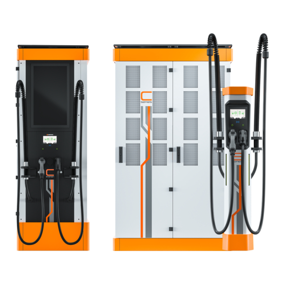
C- AND S-OPERATION MANUAL - EN 3 DEVICE 3.1 Charging system Due to the modular design of the Charging Power Unit (CPU) and flexibly located Satellite posts, charging service sites can be customized to provide the best possible charging result according to your application. Each CPU cabinet provides up to 200 kW of charging power from four power modules into one or up to eight charging plugs on Satellite posts. - Page 8 C- AND S-OPERATION MANUAL - EN Charging cable support system Welcome light Touch screen user interface RFID reader Function buttons ( 2 ) Charging plugs and plug holders (1 – 2) Status light bars (2) Figure 1. Main points of the satellite post. Depending on selected Satellite post, one or two charging cable support system springs are providing cable support that prevents cable from touching the ground, when the plug is in the holder.
-
Page 9: S-Series Ac
C- AND S-OPERATION MANUAL - EN Figure 2. Charging status. Status LEDs on the charge post indicate different states : Green- Charger ready to be used (1), Blue- Charging and state of charge (2), Red- Fault. 3.3 S-Series AC Three types of S-Series AC Satellites are available: 2 x AC sockets. -
Page 10: C-Series
C- AND S-OPERATION MANUAL - EN Touch screen user interface. RFID reader. Function buttons (2). AC plug holders (1–2). Figure 3. AC Satellite. 3.4 C-Series The C-Series, also known as "cabinet". The Charging Power Unit (CPU) consists typically 1 – 4 power modules, 0-1 Dynamic Power Module, Control module and Mains module which are fitted into racks of the cabinet. - Page 11 C- AND S-OPERATION MANUAL - EN 3G/GSM Antenna Lifting lugs (4 pcs.) Cooling outlet Power module 1 – 4 Power module channel status indicator Power module circuit breaker Power distribution module (optional) Control module ETH 1 (Eth RJ-45) ETH 1 - 8 to Sat/Cab (Eth RJ-45) to Satellite posts Reset Spare 11/11/2021 1.07...
-
Page 12: C-Station
C- AND S-OPERATION MANUAL - EN Main switch front cover plate Aux power circuit breaker Main circuit breaker Figure 4. Main points of the cabinet. 3.5 C-Station C-Station charging system consists one or two charging outlets. 11/11/2021 1.07... - Page 13 C- AND S-OPERATION MANUAL - EN 4G antenna Charging cable support system Touch screen user interface RFID reader Function buttons (2) Charging outlets 1 - 2 plug and plug holder Power modules 1 - 4 Place for power distribution module Control module MCB Auxiliary Main circuit/overload breaker...
-
Page 14: Connector Types
C- AND S-OPERATION MANUAL - EN 3.6 Connector types Figure 6. 1 = CCS (Type 2), 2 = CHAdeMO, 3 = Type 2 11/11/2021 1.07... -
Page 15: Operating Instructions
C- AND S-OPERATION MANUAL - EN 4 OPERATING INSTRUCTIONS 4.1 User Interface On each Satellite post the touch screen provides user interface. The touch screen has seven main active fields. Charging start procedure status. The different steps of the charging initialization are shown in here. -
Page 16: Charging Of Electric Vehicle
C- AND S-OPERATION MANUAL - EN Satellite post ID Info Charging protocol and available charging power Battery SoC, charged energy and remaining time Battery SoC (press battery for more detailed info) QR code for mobile following Activity button Stop Figure 8. The touch screen has seven main active fields that change during each session. 4.2 Charging of electric vehicle Prior to start DC charging the user needs to authorize charging session of the selected Satellite post. - Page 17 C- AND S-OPERATION MANUAL - EN Charging initialization starts automatically in CCS charging. Start button must be pressed in CHAdeMO charging. Figure 9. Using the Satellite post. Follow the Satellite post’s on-screen instructions. The charging status can be seen with smartphone by scanning QR-code from touch screen.
-
Page 18: Adaptive Ev Charging
C- AND S-OPERATION MANUAL - EN Ending of the charging sequence can be due to following. Battery is full - charging ends automatically when SOC level of the battery has been achieved. User presses stop button on the display or physical button below the display. Stop requires authorization when activated. -
Page 19: Adaptive Ev Charging With Arrival Priority Approach
C- AND S-OPERATION MANUAL - EN Figure 10. A simplified example of democratic power management. On a simple case - at the beginning as all EVs are charging on outputs 1-4, each EV receives 25% of the cabinet’s charging power. When the EVs on outputs 2 and 4 end charging, remaining charging power 50% is available and is routed to EVs on outputs 1 and 3 (both receives +25%). - Page 20 C- AND S-OPERATION MANUAL - EN Figure 11. A simplified example of arrival priority power management. On a simple case - at the beginning as the first EV starts to charge at 75% (150 kW), when the next EV starts to charge at output 3 it receives 25% (50 kW). As the third driver starts to charge on output 2 the first arrived still receives 75% and second and third receive only 12.5% (25 kW each).
-
Page 21: Derating Of The System In Hot Conditions
C- AND S-OPERATION MANUAL - EN 4.4 Derating of the system in hot conditions Each electric component is subject to derating in hot conditions. In case of heatwave, transformers and charging power units are subject to derating to protect themselves. Should the ambient temperature increase and demand on charging be at high level, charging power levels are automatically decreased. -
Page 22: Mechanical Drawings
C- AND S-OPERATION MANUAL - EN 5 MECHANICAL DRAWINGS 5.1 Satellite post Figure 13. Dimensions of one and two charging connectors. 11/11/2021 1.07... -
Page 23: Cpu C501/C801
C- AND S-OPERATION MANUAL - EN 5.2 CPU C501/C801 Figure 14. CPU C501/C801 11/11/2021 1.07... -
Page 24: Cpu C502/C802
C- AND S-OPERATION MANUAL - EN 5.3 CPU C502/C802 Figure 15. CPU C502/C802. 11/11/2021 1.07... -
Page 25: Cpu C503/C803
C- AND S-OPERATION MANUAL - EN 5.4 CPU C503/C803 Figure 16. CPU C503/C803. 11/11/2021 1.07... -
Page 26: C-Station
C- AND S-OPERATION MANUAL - EN 5.5 C-Station Figure 17. Dimensions. 11/11/2021 1.07... -
Page 27: Technical Specifications
C- AND S-OPERATION MANUAL - EN 6 TECHNICAL SPECIFICATIONS Table 2. Feature Description Value Input AC power connection (without transformer 3~, 380...480 V (+/-10%) (multivoltage option)) Nominal input current 262 A 524 A 786 A Input frequency 50...60 Hz Power factor (@ full load) 0.94 Efficiency 94 % @ nominal output... -
Page 28: Glossary
C- AND S-OPERATION MANUAL - EN 7 GLOSSARY AC = Alternative Current BEV = Battery Electric Vehicle – fully electric vehicle BMS = Battery Management System – battery controller CPU = Charging Power Unit CSO = Charging Service Operator – Charging provider DC = Direct Current Dia = Diameter EV = Electric Vehicle –... - Page 29 Kempower Oy Hennalankatu 71 P.O. BOX 13 15801 Lahti, Finland Tel. +358290021900 kempower.com Subject to change without notice © Kempower 2021...
Need help?
Do you have a question about the S Series and is the answer not in the manual?
Questions and answers