Table of Contents
Advertisement
Advertisement
Table of Contents

Related Manuals for Acer Aspire M3450


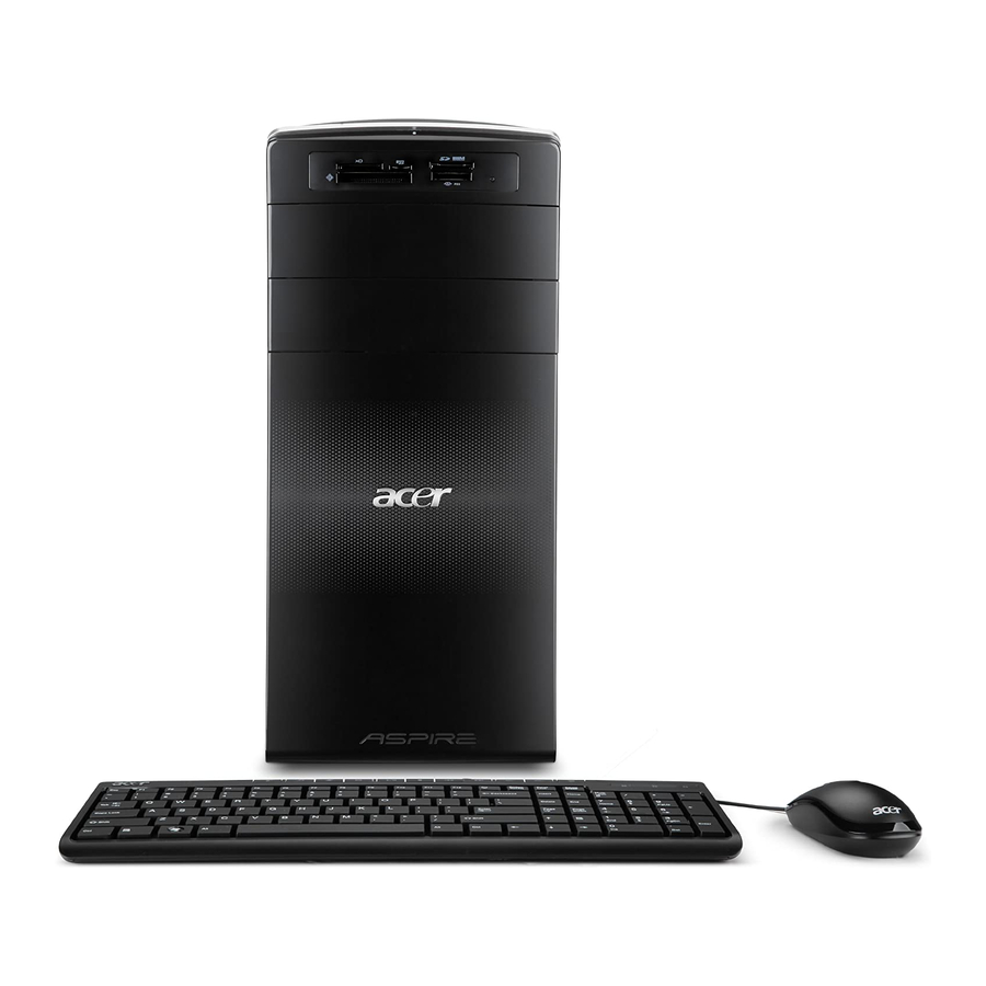
Summary of Contents for Acer Aspire M3450
- Page 1 Acer Aspire M3450 Service Guide PRINTED IN TAIWAN...
-
Page 2: Revision History
Revision History Please refer to the table below for the updates made on this service guide. Date Chapter Updates... - Page 3 Copyright Copyright © 2011 by Acer Incorporated. All rights reserved. No part of this publication may be reproduced, transmitted, transcribed, stored in a retrieval system, or translated into any language or computer language, in any form or by any means, electronic, mechanical, magnetic, optical, chemical, manual or otherwise, without the prior written permission of Acer Incorporated.
- Page 4 Disclaimer The information in this guide is subject to change without notice. Acer Incorporated makes no representations or warranties, either expressed or implied, with respect to the contents hereof and specifically disclaims any warranties of merchantability or fitness for any particular purpose.
- Page 5 Conventions The following conventions are used in this manual: SCREEN Denotes actual messages that appear on screen. MESSAGES NOTE Gives additional information related to the current topic. WARNING Alerts you to any physical risk or system damage that might result from doing or not doing specific actions.
-
Page 6: Fru Information
Service Guide Coverage This Service Guide provides you with all technical information relating to the BASIC CONFIGURATION decided for Acer's "global" product offering. To better fit local market requirements and enhance product competitiveness, your regional office MAY have decided to extend the functionality of a machine (e.g. add-on card, modem, or extra memory capability). -
Page 7: Table Of Contents
Table of Contents System Tour Features Block Diagram System Components Front Panel Rear Panel Hardware Specifications and Configurations Power Management Function(ACPI support function) System Utilities CMOS Setup Utility Entering CMOS setup Navigating Through the Setup Utility Setup Utility Menus System Disassembly and Assembly Disassembly Requirements Pre-disassembly Procedure Removing the Side Panel... - Page 8 System Check Procedures Power System Check System External Inspection System Internal Inspection Beep Codes Checkpoints BIOS Recovery Jumper and Connector Information M/B Placement Jumper Setting Setting Jumper FRU (Field Replaceable Unit) List Aspire M3450 Exploded Diagram Aspire M3450 FRU List viii...
-
Page 9: System Tour
Chapter 1 System Tour Features Below is a brief summary of the computer’s many feature: NOTE: The features listed in this section is for your reference only. The exact configuration of the system depends on the model purchased. Operating System Microsoft Windows 7 Home Premium x64 •... -
Page 10: Onboard Graphics Solution
Onboard Graphics Solution AMD RS880P on die graphic solution • Dual independent display -- HDMI and D-Sub. • Meet Microsoft Windows 7 Premium graphic requirement. • Digital display HDMI with HDMI CTS 1.4 compliance. • Need to measure VGA follow Acer VGA SOP. •... - Page 11 Extension slot 1 PCI Express x16 slot • 2 PCI Express x1 • 1 PCI slot • USB 2.0 ports Controller: AMD SB950. • Ports Quantity: 12 • 6 port for rear ports. • 4 ports for front daughter board. •...
-
Page 12: System Bios
System BIOS AMI BIOS with 32Mb SPI Flash ROM. • AMI Kernel with Acer skin/copyright. • Supports Multi-language BIOS Utility. • Power supply 300W/500W(Support models are listed on AVLC). • Chapter 1... -
Page 13: Block Diagram
Block Diagram Chapter 1... -
Page 14: System Components
System Components This section is a virtual tour of the system’s interior and exterior components. Front Panel Component USB 2.0 ports Slave optical drive eject button HDD activity indicator Master optical drive eject button Press to open drive bay door and access the optical drive. -
Page 15: Rear Panel
Rear Panel Component Power connector PS2 keyboard port HDMI port VGA port USB 3.0 ports USB 2.0 ports Microphone jack Line-out Expansion slot (graphics card and TV tuner card and Mode card) Line-in USB 2.0 ports LAN connector System FAN PS2 mouse port Chapter 1... -
Page 16: Hardware Specifications And Configurations
Hardware Specifications and Configurations Processor Item Specification Processor Type AMD AM3 and FX series CPU(Max: 95W) Socket Type AMD Socket AM3+ Minimum operating speed 0 MHz (If Stop CPU Clock in Sleep State in BIOS Setup is set to Enabled.) BIOS Item Specification... -
Page 17: Memory Combinations
Memory Combinations Slot Memory Total Memory Slot 1 1MB,2GB,4GB 1G ~4GB Slot 2 1MB,2GB,4GB 1G ~4GB Slot 3 1MB,2GB,4GB 1G ~4GB Slot 4 1MB,2GB,4GB 1G ~4GB Maximum System Memory Supported 1G~16GB System Memory Item Specification Memory slot number 4 slot Support Memory size per socket 1GB/2GB/4GB Support memory type... -
Page 18: Sata Interface
SATA Interface Item Specification SATA controller AMD SB950 Number of SATA channel SATA X 6(SATA 6Gb/s) Support mode RAID/AHCI/IDE mode option USB Port Item Specification Universal HCI USB 2.0/1.1 or 3.0 USB Class Support legacy keyboard for legacy mode USB Connectors Quantity USB2.0 Ports Quantity: 12 •... -
Page 19: Power Management Function(Acpi Support Function)
Power Management Function(ACPI support function) Device Standby Mode Independent power management timer for hard disk drive devices(0-15 minutes,time step=1minute). • Hard Disk drive goes into Standby mode(for ATA standard interface). • Disable V-sync to control the VESA DPMS monitor. • Resume method:device activated (keyboard for DOS, keyboard &mouse for Windows. -
Page 20: System Utilities
Chapter 2 System Utilities CMOS Setup Utility CMOS setup is a hardware configuration program built into the system ROM, called the complementary metal- oxide semiconductor (CMOS) Setup Utility. Since most systems are already properly configured and optimized, there is no need to run this utility. You will need to run this utility under the following conditions. When changing the system configuration settings •... -
Page 21: Entering Cmos Setup
Entering CMOS setup Turn on the server and the monitor. If the server is already turned on, close all open applications, then restart the server. During POST, press Delete. If you fail to press Delete before POST is completed, you will need to restart the server. The Setup Main menu will be displayed showing the Setup’s menu bar. -
Page 22: Setup Utility Menus
Setup Utility Menus Main The Setup Main menu includes the following main setup categories. Parameter Description System BIOS Version Version number of the BIOS setup utility. Build Date Date when the BIOS setup utility was built Processor Type of CPU installed on the system. Core Frequency Core speed of the CPU installed on the system. - Page 23 Advanced Parameter Description Miscellaneous Press Enter to access the Miscellaneous submenu Advanced Chipset Configuration Press Enter to access the Advanced Chipset Configuration submenu Integrated Peripherals Press Enter to access the Integrated Peripherals submenu PC Health Status Press Enter to access the PC Health Status submenu Chapter 2...
- Page 24 Miscellaneous Parameter Description Option AHCI Port1/2/3/4/5/6 Displays the status of auto detection of the AHCI device. Clock to All DIMM/ This item allows you to enable or disable the Clock to all DIMM/PCI/PCIE. Enabled PCI/PCIE Disabled Spread Spectrum Enables or disables the reduction of the mainboard’s EMI. Note: Remember to Enabled disable the Spread Spectrum feature if you are overclocking.
-
Page 25: Advanced Chipset Configuration
Advanced Chipset Configuration AMD Turbo Core This item allows you to enable or disable the AMD Turbo Core. Enabled Disabled AMD Cool’n’Quiet This item allows you to enable/disable your system utilize the AMD specific Enabled ACPI states to save power consumption. Disabled AMD EVP This item allows you to enable or disable the AMD EVP. -
Page 26: Integrated Peripherals
Integrated Peripherals Parameter Description Option Onboard SATA Controller Enables or disables the onboard SATA controller. Enabled Disabled Onboard SATA Mode Select an operating mode for the onboard SATA. Native IDE RAID AHCI Onboard USB Controller Enables or disables the onboard USB controller. Enabled Disabled Legacy USB Support... -
Page 27: Pc Health Status
PC Health Status Parameter Description Option Smart Fan Enables or disables the smart system fan control function. Enabled Disabled Chapter 2... - Page 28 Power Parameter Description Option ACPI Suspend Mode Select an ACPI state. S3 (STR) S1 (POS) Deep Power Off Mode Select the Deep power off Mode Enabled Disabled Power On by RTC Alarm Enables or Disables to wake up the system by RTC Alarm Function Enabled Disabled Power On by PCIE Devices...
- Page 29 Security Parameter Description Option Supervisor Password This item indicates whether a supervisor password has been set. If the password has been installed, Installed displays. If not, Not Installed displays. User Password This item allows you to change user password. Change Supervisor You can select this option and press <Enter>...
-
Page 30: Boot Options
Boot Options 1st/2nd/3rd/4th/5th Boot Specifies the boot order from the available devices. Device Hard Disk CD^DVD Removable Device EFI Device Priority Press Enter to access the EFI Device Priority submenu and specify the boot device priority sequence from available EFI devices. Hard Disk Drive Priority Press Enter to access the Hard Disk Drive Priority submenu and specify the boot device priority sequence from available hard drives. - Page 31 Exit Parameter Description Save & Exit Setup When you have completed the system configuration changes, select this option to leave the BIOS Setup Utility and reboot the computer, so the new system configuration parameters can Save & Exit Setup Enter take effect.
-
Page 32: System Disassembly And Assembly
Chapter 3 System Disassembly and Assembly This chapter contains step-by-step procedures on how to disassemble and assembly the desktop computer for maintenance and troubleshooting. Disassembly Requirements To disassemble the computer, you need the following tools: Wrist grounding strap and conductive mat for preventing electrostatic discharge •... -
Page 33: Pre-Disassembly Procedure
Pre-disassembly Procedure Before proceeding with the disassembly procedure, perform the steps listed below: Turn off the system and all the peripherals connected to it. Unplug the power cord from the power outlets. Unplug the power cord from the system. Unplug all peripheral cables from the system. Place the system unit on a flat, stable surface. -
Page 34: Removing The Side Panel
Removing the Side Panel Remove the two screws located on the rear edge of the side panel. Slide the side panel toward the back of the chassis until the tabs on the cover disengage with the slots on the chassis. Lift the side panel away from the server and put it aside for reinstallation later. -
Page 35: Removing The Front Bezel
Removing the Front Bezel Remove the side panel. Refer to the previous section for instructions. Release the front bezel from the chassis interior. Pull the bezel away from the chassis. Chapter 3... -
Page 36: Removing The Heat Sink Fan Assembly
Removing the Heat Sink Fan Assembly WARNING:The heat sink becomes very hot when the system is on. NEVER touch the heat sink with any metal or with your hands. Loosen the hook of heat sink as shown below. Disconnect two tache of heat sink(1)&(2)away from the bracket. Note :CPU Fan has been highlighted with the yellow rectangle as above image shows.Please detach the CPU Fan and follow local regulations for disposal. - Page 37 Lift the heat sink fan assembly away from the mainboard. Lay down the heat sink fan assembly, in an upright position, on top of the power supply, as shown below, then disconnect the fan cable from the mainboard. Remove the heat sink fan assembly from the chassis then lay it down in an upright position—with the thermal patch facing upward.
-
Page 38: Removing The Processor
Removing the Processor IMPORTANT:Before removing a processor from the mainboard, make sure to create a backup file of all important data. WARNING:The processor becomes very hot when the system is on. Allow it to cool off first before handling. Release the load lever. Lift the load lever to the fully open, upright position. - Page 39 Pull out the processor from the socket. IMPORTANT: If you are going to install a new processor, note the arrow on the corner to make sure the processor is properly oriented over the socket. Chapter 3...
-
Page 40: Removing The Vga Card
Removing the VGA Card Remove the four screws that secures the card to the chassis. Open PCI Latch. Chapter 3... - Page 41 Firstly press retention latch down to unlock the card from the PCI slot., then gently pull the card to remove it from the mainboard. Note: Circuit boards >10 cm² has been highlighted with the yellow rectangle as above image shows. Please detach the Circuit boards and follow local regulations for disposal.
-
Page 42: Removing The Tv-Tuner Card
Removing the TV-Tuner Card Gently pull the card to remove it from the mainboard. Note: Circuit boards >10 cm² has been highlighted with the yellow rectangle as above image shows. Please detach the Circuit boards and follow local regulations for disposal. Chapter 3... -
Page 43: Removing The Pci-E Modem Card
Removing the PCI-E Modem Card Gently pull the card to remove it from the mainboard. Note: Circuit boards >10 cm² has been highlighted with the yellow rectangle as above image shows. Please detach the Circuit boards and follow local regulations for disposal. Chapter 3... -
Page 44: Removing The Wireless Lan Card
Removing the Wireless Lan Card Gently pull the card to remove it from the mainboard. Note: Circuit boards >10 cm² has been highlighted with the yellow rectangle as above image shows. Please detach the Circuit boards and follow local regulations for disposal. Chapter 3... -
Page 45: Removing The Memory Modules
Removing the Memory Modules IMPORTANT:Before removing any DIMM from the memory board, make sure to create a backup file of all important data. Press the holding clips on both sides of the DIMM slot outward to release the DIMM(1). Gently pull the DIMM upward to pull it away from the M/B(2). Note: Circuit boards >10 cm²... -
Page 46: Removing The Hard Disk Drive
Removing the Hard Disk Drive Disconnect the data and power cables from the rear of the optical drive. Disconnect the other end of the data cable from the main board. Remove the screw that secures the HDD cage to the chassis. Chapter 3... - Page 47 Lift the HDD cage up and turn it over. Remove the HDD module. Remove the four screws secure the HDD module to the HDD cage. Slide the HDD out of the cage. Chapter 3...
-
Page 48: Removing The Optical Drive
Removing the Optical Drive Use a knife to cut off the PE belt then disconnector the cable. Disconnect data and power cable from the rear of the optical drive. Disconnect the other end of the data cable from the mainboard. Chapter 3... - Page 49 Remove the four screws from the optical drive. Pull the master ODD from the chassis. Pull the slave ODD from the chassis with the same way. Chapter 3...
-
Page 50: Removing The System Fan
Removing the System Fan Remove system FAN cable from Main board. Release four screws according to the following picture. Chapter 3... - Page 51 Take off the system fan from chassis. Note :System fan has been highlighted with the yellow rectangle as above image shows.Please detach the system fan and follow local regulations for disposal. Chapter 3...
-
Page 52: Removing The Daughter Board
Removing the Daughter Board Take out the cable from the cable retention clip, and disconnect the daughter board cable from the motherboard. Remove the screw that secures the chassis to the daughter board. Take out the daughter board. Chapter 3... -
Page 53: Removing The Power Supply
Removing the Power Supply Disconnect the 4-pin and 24-pin power supply cables from the mainboard. Remove the four screws that secures the power supply to the chassis. Lift the power supply module out of the chassis. Chapter 3... -
Page 54: Removing The Mainboard
Removing the Mainboard Open the cable retention clip, then take out the these cables from the cable retention clip. Disconnect the power switch cable/top audio cable/top USB cable/card reader cable from the main board. Release the the cable retention clip. Chapter 3... - Page 55 Remove the eight screws that secure the mainboard to the chassis. Note: Circuit boards >10 cm² has been highlighted with the yellow rectangle as above image shows. Please detach the Circuit boards and follow local regulations for disposal. Lift the board from the chassis. Chapter 3...
- Page 56 Punching in IO Shield then you can remove it. Remove the RTC battery. Note: RTC battery has been highlighted with the yellow circle as above image shows.Please detach the RTC battery and follow local regulations for disposal. Chapter 3...
-
Page 57: Removing The Top Cover
Removing the Top Cover Gently release the top bezel retention tabs from the chassis interior. When perform the step one, then release the top bezel retention tabs from the chassis interior. Chapter 3... - Page 58 Pull the top cover away from the chassis. Pull the power switch and LED cable from chassis hole. Chapter 3...
-
Page 59: Removing The Power Switch And Led Cable Assembly
Removing the Power Switch and LED Cable Assembly Release the locking tabs (1) and gently power switch cable out of the bracket (2). Release the locking tabs (1) and gently LED cable out of the bracket (2). Release the two locking tabs and take out the cable. Chapter 3... -
Page 60: Removing The Card Reader
Removing the Card Reader Removing the two screws from the chassis. Lift the card reader away from chassiss. then Pull the card reader cable from chassis hole. Chapter 3... -
Page 61: Removing The Top Usb And Audio I/O Assembly
Removing the Top USB and Audio I/O Assembly Removing the two screws from the chassis. Release these cables from the chassis. Lift the top USB and audio I/O assembly away from chassiss. Chapter 3... - Page 62 Removing the top USB and audio I/O board. Use screwdriver to remove the two screws. Grasp the bracket then gently Pull the USB board out of the bracket. Chapter 3...
-
Page 63: Assembly Requirements
Assembly Requirements To assemble the computer, you need the following tools: Wrist grounding strap and conductive mat for preventing electrostatic discharge • Flat-blade screwdriver • Philips screwdriver • Hex screwdriver • Plastic flat-blade screwdriver • Plastic tweezers • NOTE: The screws for the different components vary in size. During the assembly process, group the screws with the corresponding components to avoid mismatch when putting back the components. -
Page 64: Assembly Procedure
Assembly Procedure Before proceeding with the assembly procedure, perform the steps listed below: Turn off the system and all the peripherals connected to it. Unplug the power cord from the power outlets. Unplug the power cord from the system. Unplug all peripheral cables from the system. Place the system unit on a flat, stable surface. -
Page 65: Install The Processor
Install the Processor Release the load lever and lift the load lever to the fully open. Put the CPU in the seat and close the load plate and load lever. NOTE: When you install the processor, note the arrow on the corner to make sure the processor is properly oriented over the socket. -
Page 66: Install The Heat Sink Fan Assembly
Install the Heat Sink Fan Assembly Put the CPU cooler on M/B retention module. Install the two taches of cooler to bracket. Chapter 3... - Page 67 Lock the CPU cooler. Connect the cooler cable to the main board. Chapter 3...
-
Page 68: Install The Memory
Install the Memory Open the holding clips on both sides of the DIMM slot outward. Press down the memory. IMPORTANT:pls refer to below installing memory rule. DIMM1 DIMM2 DIMM3 DIMM4 Remark:A and B show different size of memory, size:A>B Chapter 3... -
Page 69: Romoving The Side Panel
Removing the Side Panel Remove the four screws located on the rear edge of the side panel. Slide the side panel toward the back of the chassis until the tabs on the cover disengage with the slots on the chassis. Lift the side panel away from the server and put it aside for reinstallation later. -
Page 70: Removing The Daughter Board
Removing the Daughter Board Remove the screw that secures the chassis to the daughter board. Take out the daughter board. Chapter 3... -
Page 71: Removing The Cage Of Hard Disk Drive
Removing the Cage of Hard Disk Drive Remove the screw that secures the HDD cage to the chassis. Lift the HDD cage up and turn it over. Chapter 3... -
Page 72: Removing The Pci Cover
Removing the PCI Cover Remove the PCI cover. NOTE: Based to actual requirment to remove the PCI cover. Chapter 3... -
Page 73: Install The Power Supply
Install the Power Supply Install the power supply to chassis. Fix the four screws. Chapter 3... -
Page 74: Install The I/O Shielding
Install the I/O Shielding Install I/O shielding into chassis. Chapter 3... -
Page 75: Install The Main Board
Install the Main Board Put M/B in the chassis aligning the M/B I/O connector with I/O shielding. Fix1~ 8 pcs screws into the corresponding hole. NOTE: Make sure the I/O spring touching M/B after installing. Connect the ATX 24Pin Power cable and ATX 4Pin Power cable to main board. Chapter 3... - Page 76 Connector the Power switch/Top USB/Card Reader/Audio cable to motherboard, and put the power switch cable/top USB cable/card reader USB cable/top audio cable into the cable retention clip, then close the cable retention clip. Chapter 3...
-
Page 77: Install The Optical Drive
Install the Optica Drive Removing the front bezel, please refer to “Removing the front bezel” on page 27. Install the ODD into chassis. Fix the four screws. Chapter 3... - Page 78 Connect the power cables and data cable to the rear of the optical drive. Connect the other end of the data cable to the mainboard. Chapter 3...
-
Page 79: Install The Hard Disk Drive
Install the Hard Disk Drive Install the HDD. Install the slave HDD into the cage. Fix four screws for the slave HDD. Install the master HDD into the cage. Chapter 3... - Page 80 Fix four screws for the master HDD. Install HDD cage into chassis by the track. Fix the screw. Chapter 3...
- Page 81 Let the data cable through the bracket. Connect the data cable and power cable to the rear of the hard disk drive. Connect the other end of the data cable to the main board. Chapter 3...
-
Page 82: Install The Daughter Board
Install the Daughter Board Install the daughter board into chassis. Fix the screw. Connect the daughter board cable to the motherboard. then paste cable clip to base of chassis, and put daughter board cable into the cable clip. Chapter 3... -
Page 83: Install The System Fan
Install the System FAN Push the system fan to chassis. Fix the four screws. Connect the system fan power cable to Main board. Chapter 3... -
Page 84: Install The Wireless Lan Card
Install the Wireless LAN Card Open PCI Latch. Install the wireless LAN card to motherboard “PCIE X1” slot. NOTE: You install before the card, rear USB cable througt the wireless Lan card underside. Chapter 3... -
Page 85: Install The Pci-E Modem Card
Install the PCI-E Modem Card Install the PCI-E modem card to motherboard “PCIE X1” slot. NOTE: You install before the card, rear USB cable througt the PCI-E modem card underside. Chapter 3... -
Page 86: Install The Tv-Tuner Card
Install the the TV-Tuner Card Install the TV-Tuner card to motherboard “PCIE X1” slot. NOTE: You install before the card, rear USB cable througt the TV-Tuner card underside. Chapter 3... -
Page 87: Install The Vga Card
Install the VGA Card Install the VGA card to motherboard “PCIE X16” slot. NOTE: You install before the card, rear USB cable througt the VGA card underside. Close the PCI Latch, fix the three screws. Chapter 3... -
Page 88: Install The Front Bezel
Install the Front Bezel Clear up these cables. then use PE belt to bundle these cables. Install the panel onto chassis and then check if it is Installed OK. Chapter 3... -
Page 89: Install The Side Panel
Install the Side Panel Install the side Panel, then fix two Screws. Chapter 3... -
Page 90: System Troubleshooting
Chapter 4 System Troubleshooting This chapter provides instructions on how to troubleshoot system hardware problems. Hardware Diagnostic Procedure IMPORTANT:The diagnostic tests described in this chapter are only intended to test Acer products. Non- Acerproducts, prototype cards, or modified options can give false errors and invalid systemresponses. -
Page 91: System Check Procedures
System Check Procedures Power System Check If the system will power on, skip this section. Refer to System External Inspection. If the system will not power on, do the following: Check if the power cable is properly connected to the system and AC source. •... -
Page 92: Beep Codes
Beep Codes Beep codes are used by the BIOS to indicate a serious or fatal error to the end user. Beep codes are used when an error occurs before the system video has been initialized. Beep codes will be generated by the system board speaker, commonly referred to as the PC speaker. -
Page 93: Checkpoints
Checkpoints A checkpoint is either a byte or word value output to I/O port 80h.The BIOS outputs checkpoints throughout bootblock and Power-On Self Test (POST) to indicate the task the system is currently executing. Checkpoint sare very useful in aiding software developers or technicians in debugging problems that occur during the pre- boot process. - Page 94 Checkpoint Description Restore CPUID value back into register. Give control to BIOS POST (ExecutePOSTKernel). See POST Code Checkpoints section of document for more information. System is waking from ACPI S3 state. E1-E8 EC- OEM memory detection/configuration error. This range is reserved for chipset vendors & system manufacturers.
-
Page 95: Bootblock Recovery Code Checkpoints
Bootblock Recovery Code Checkpoints The Bootblock recovery code gets control when the BIOS determines that a BIOS recovery needs to occur because the user has forced the update or the BIOS checksum is corrupt. The following table describes the type of checkpoints that may occur during the Bootblock recovery portion of the BIOS. NOTE: Checkpoints may differ between different platforms based on system configuration. -
Page 96: Bios Recovery
BIOS Recovery AMIBIOS supports a "recovery flash" mode, which can be used to flash update a BIOS from the boot block. This is used to update a BIOS image without the need to boot to an operating system. The following is the process that user should follow to flash BIOS ROM. -
Page 97: Jumper And Connector Information
Chapter 5 Jumper and Connector Information M/B Placement Chapter 5... - Page 98 Label Description CPU Socket Supports AMD AM3/AM3+ CPUs CPU_FAN 4-pin CPU cooling fan connector DDR3_1~4 240-pin DDR3 SDRAM slots ATX_POWER Standard 24-pin ATX power connector SATA1~6 Serial ATA 6.0 Gb/s connectors F_PANEL Front panel switch/LED header F_USB1~4 Front panel USB 2.0 header F_AUDIO Front panel audio header 32-bit add-on card slot...
-
Page 99: Jumper Setting
Jumper Setting The section explains how to set jumper for correct configuration of the mainboard. Setting Jumper Use the motherboard jumpers to set system configuration options. Jumpers with more Than one pin are numbered. When setting the jumpers, ensure that the jumper caps are Placed on the correct pins. The illustrations show a 2-pin jumper. -
Page 100: Checking Jumper Settings
Checking Jumper Settings The following illustration shows the location of the motherboard jumpers. Pin 1 is labeled. Jumper Settings Jumper Type Description Setting (default) CLR_CMOS 3-pin CLEAR CMOS 1-2: NORMAL 2-3: CLEAR Before clearing the CMOS, make sure to turn the system off. Chapter 5... -
Page 101: Checking Connector
Checking Connector Connecting Optional Devices F_AUDIO: Front Panel Audio heade This header allows the user to install auxiliary front-oriented microphone and line-out ports for easier access. Signal Name Signal Name PORT 1L AUD_GND PORT 1R PRESENCE# PORT 2R SENSE1_RETURN SENSE_SEND PORT 2L SENSE2_RETURN Chapter 5... - Page 102 SATA1~6: Serial ATA connectors These connectors are used to support the new Serial ATA devices for the highest date transfer rates (6.0 Gb/ s), simpler disk drive cabling and easier PC assembly. It eliminates limitations of the current Parallel ATA interface.
- Page 103 Connecting I/O Devices The backplane of the motherboard has the following I/O ports: I/O Port Name I/O Port Function PS2 Mouse Use the upper PS/2 port to connect a PS/2 pointing device. PS2 Keyboard Use the lower PS/2 port to connect a PS/2 keyboard. HDMI Port Connect the HDMI port to the HDMI device.
-
Page 104: Connecting Case Components
Connecting Case Components CPU_FAN: CPU cooling FAN Power Connector Signal Name Function System Ground +12V Power +12V Sense Sensor CONTROL CONTROL SYS_FAN: System Cooling FAN Power Connector Signal Name Function System Ground +12V Power +12V Sense Sensor Chapter 5... -
Page 105: Atx 24-Pin Power Connector
ATX_ POWER: ATX 24-pin Power Connector Signal Name Signal Name +3.3V +3.3V +3.3V -12V PS_ON PWR OK +5VSB +12V +12V +3.3V ATX12V: ATX 12V Power Connector Signal Name Ground Ground +12V +12V Front Panel Header The front panel header (F_PANEL) provides a standard set of switch and LEDheaders commonly found on ATX or micro-ATX cases. -
Page 106: Fru (Field Replaceable Unit) List
Chapter 6 FRU (Field Replaceable Unit) List This chapter offers the FRU (Field Replaceable Unit) list in global configuration of the Aspire M3450 desktop computer. Refer to this chapter whenever ordering the parts to repair or for RMA (Return Merchandise Authorization). -
Page 107: Aspire M3450 Exploded Diagram
Aspire M3450 Exploded Diagram NOTE: This section will be updated when more information becomes available. Chapter 6... - Page 108 ITEM NAME Q’TY ITEM NAME Q’TY PCI Door ODD Button Dn Rear Chassis Pole IO Shielding ODD Door Up Power Supply ODD Door Dn Deco Bezel Chassis Support Acer Logo Chassis Support Hinge ODD Door MB Support Main Bezel Sub Chassis Holder Bezel Top Bezel Front Chassis...
-
Page 109: Aspire M3450 Fru List
Aspire G3120 FRU List Exploded Category Part Number Acer P/N Diagram Item aPalmer_II MB.SH307.003 E980GM_1394(N)_LOGO(Y)_USB3.0(Y) (125W) Chassis Aspire 2011 M3 w/o HDD carrier HS.13100.212 Aspire 2011 M3 w/ HDD carrier HS.13100.213 Bezel Aspire 2011 M3 w/o HDD carrier PZ.11900.244 Aspire 2011 M3 w/ HDD carrier PZ.11900.245 CPU Cooler Fan Cooler K8_M2 FXC PKP482 Fan8025... - Page 110 Exploded Category Part Number Acer P/N Diagram Item "AMD FX-8100, 8-core, 8MB L3 cache, 95W" KC.FX002.810 "AMD FX-6100, 6-core, 8MB L3 cache, 95W" KC.FX002.610 "AMD FX-4100, 4-core, 8MB L3 cache, 95W" KC.FX002.410 "AMD Phenom II X6 1065T, 6-core, 6M L3 cache, KC.PU202.65T 95W"...
- Page 111 Exploded Category Part Number Acer P/N Diagram Item "AMD Phenom II X2 565, 80W" KC.PH202.565 "AMD Phenom II X2 560, 80W" KC.PH202.560 "AMD Phenom II X2 555, 80W" KC.PH202.555 AMD Phenom II x2 B57 KC.PH202.B57 AMD Phenom II x2 B55 KC.PH202.B55 AMD Phenom II x2 B53 KC.PH202.B53...
- Page 112 Exploded Category Part Number Acer P/N Diagram Item 4GB DDR3 1333MHz KN.4GB03.006 4GB DDR3 1333MHz KN.4GB04.002 4GB DDR3 1333MHz KN.4GB0H.001 "HDD HGST 3.5"" 7200rpm 160GB KH.16007.027 HDS721016CLA382 ( Jupiter) SATA II 8MB LF F/ W:3EA" "HDD HGST 3.5"" 7200rpm 320GB KH.32007.011 HDS721032CLA362 (Jupiter) SATA II 16MB LF F/ W:3EA"...
- Page 113 Exploded Category Part Number Acer P/N Diagram Item "HDD WD 3.5"" 5400rpm 1000GB WD10EARS- KH.01K08.008 22Y5B1 (GP500M-2D 4K sector) SATA II LF F/ W:80.00A80" "HDD WD 3.5"" 5400rpm 1500GB WD15EARS- KH.15K08.003 22MVWB0 (GP667-3D) SATA II 64MB LF F/ W:50.0AB50" "HDD WD 3.5"" 5400rpm 2000GB WD20EARS- KH.02K08.006 22MVWB0(GP667-3D) SATA II LF F/W:50.0AB50"...
- Page 114 Exploded Category Part Number Acer P/N Diagram Item 288-1N162-201AC GT420 1GB 128bits sDDR3 VG.PCPT4.221 VGA+DVI+HDMI SAMSUNG ATX 288-1N162-301AC GT420 1GB 128bits sDDR3 VG.PCPT4.222 VGA+DVI+HDMI HYNIX ATX 288-5E142-001AC HD6570 1GB DDR3 128BITS VG.APC65.701 DVI-I (SL) HDMI SAMSUNG ATX BRACKET 288-5E142-201AC HD6570 1GB DDR3 128BITS VG.APC65.703 DVI-I (SL) HDMI HYNIX DFR-die ATX 288-5N158-020AC 405 1GB 64bits DDR3 DVI +...
- Page 115 Exploded Category Part Number Acer P/N Diagram Item TV-Tuner Avermedia H753-A TV Tuner Card PCIe Hybrid TU.10500.072 ATSC, S/W Encoder, ATX bracket Avermedia H753-D TV Tuner Card PCIe Hybrid TU.10500.074 DVB-T, S/W Encoder, ATX bracket H753-C, ATX, GC TU.10500.078 Card Reader M3 15-in-1 Card Reader CR.10400.137 Modem...
- Page 116 Exploded Category Part Number Acer P/N Diagram Item Receiver Philips OVU710018 Win7 receiver Philips code for RV.11000.025 EMEA, H57 fixed FW, pair with RT.11300.021 Philips Vista receiver OVU71 RV.11000.007 Philips Win7 OVU430008 with IR blaste RV.11000.023 WLAN WN7601R, Ralink RT3090, 802.11b/g/n 1x1 NI.10200.037 WLAN PCI-E x1 card External Speaker...
- Page 117 Exploded Category Part Number Acer P/N Diagram Item Lite-on RF2.4 SM-9063B with receiver(nano MS.11200.094 dangle); without battery Keyboard Keyboard LITE-ON SK-9660B RF2.4 104KS Black KB.RF40B.042 Keyboard LITE-ON SK-9660B RF2.4 104KS Black KB.RF40B.043 Traditional Chinese Keyboard LITE-ON SK-9660B RF2.4 104KS Black KB.RF40B.044 Simplified Chinese Keyboard LITE-ON SK-9660B RF2.4 104KS Black...
- Page 118 Exploded Category Part Number Acer P/N Diagram Item Keyboard LITE-ON SK-9660B RF2.4 104KS Black KB.RF40B.063 Hebrew Keyboard LITE-ON SK-9660B RF2.4 105KS Black KB.RF40B.064 Polish Keyboard LITE-ON SK-9660B RF2.4 105KS Black KB.RF40B.065 Slovenian Keyboard LITE-ON SK-9660B RF2.4 105KS Black KB.RF40B.066 Slovak Keyboard LITE-ON SK-9660B RF2.4 104KS Black KB.RF40B.067 Russian...
- Page 119 Exploded Category Part Number Acer P/N Diagram Item Keyboard PRIMAX KBRF36211 RF2.4 104KS KB.RF40P.001 Black US Keyboard PRIMAX KBRF36211 RF2.4 104KS KB.RF40P.002 Black Traditional Chinese Keyboard PRIMAX KBRF36211 RF2.4 104KS KB.RF40P.003 Black Simplified Chinese Keyboard PRIMAX KBRF36211 RF2.4 104KS KB.RF40P.004 Black US International Keyboard PRIMAX KBRF36211 RF2.4 104KS KB.RF40P.005...
- Page 120 Exploded Category Part Number Acer P/N Diagram Item Keyboard PRIMAX KBRF36211 RF2.4 105KS KB.RF40P.023 Black Polish Keyboard PRIMAX KBRF36211 RF2.4 105KS KB.RF40P.024 Black Slovenian Keyboard PRIMAX KBRF36211 RF2.4 105KS KB.RF40P.025 Black Slovak Keyboard PRIMAX KBRF36211 RF2.4 104KS KB.RF40P.026 Black Russian Keyboard PRIMAX KBRF36211 RF2.4 105KS KB.RF40P.027 Black Hungarian...
- Page 121 Exploded Category Part Number Acer P/N Diagram Item Keyboard LITE-ON SK-9621B USB 104KS Black KB.USB0B.331 Traditional Chinese Keyboard LITE-ON SK-9621B USB 104KS Black KB.USB0B.332 Simplified Chinese Keyboard LITE-ON SK-9621B USB 104KS Black KB.USB0B.333 US International Keyboard LITE-ON SK-9621B USB 104KS Black KB.USB0B.334 Arabic/English Keyboard LITE-ON SK-9621B USB 104KS Black...
- Page 122 Exploded Category Part Number Acer P/N Diagram Item Keyboard LITE-ON SK-9621B USB 105KS Black KB.USB0B.353 Slovenian Keyboard LITE-ON SK-9621B USB 105KS Black KB.USB0B.354 Slovak Keyboard LITE-ON SK-9621B USB 104KS Black KB.USB0B.355 Russian Keyboard LITE-ON SK-9621B USB 105KS Black KB.USB0B.356 Hungarian Keyboard LITE-ON SK-9621B USB 104KS Black KB.USB0B.357 Greek...
- Page 123 Exploded Category Part Number Acer P/N Diagram Item Keyboard PRIMAX KB36211 USB 104KS Black KB.USB0P.004 US International Keyboard PRIMAX KB36211 USB 104KS Black KB.USB0P.005 Arabic/English Keyboard PRIMAX KB36211 USB 104KS Black KB.USB0P.006 Thailand Keyboard PRIMAX KB36211 USB 105KS Black KB.USB0P.007 Spanish Keyboard PRIMAX KB36211 USB 105KS Black KB.USB0P.008...
- Page 124 Exploded Category Part Number Acer P/N Diagram Item Keyboard PRIMAX KB36211 USB 104KS Black KB.USB0P.026 Russian Keyboard PRIMAX KB36211 USB 105KS Black KB.USB0P.027 Hungarian Keyboard PRIMAX KB36211 USB 104KS Black KB.USB0P.028 Greek Keyboard PRIMAX KB36211 USB 105KS Black KB.USB0P.029 Danish Keyboard PRIMAX KB36211 USB 104KS Black KB.USB0P.030 Czech...
- Page 125 Exploded Category Part Number Acer P/N Diagram Item Keyboard LITE-ON SK-9611 PS/2 104KS Black KB.PS20B.120 Thailand Keyboard LITE-ON SK-9611 PS/2 105KS Black KB.PS20B.121 Spanish Keyboard LITE-ON SK-9611 PS/2 105KS Black KB.PS20B.122 Portuguese Keyboard LITE-ON SK-9611 PS/2 105KS Black KB.PS20B.123 Canadian French Keyboard LITE-ON SK-9611 PS/2 107KS Black KB.PS20B.124 Brazilian Portuguese...
- Page 126 Exploded Category Part Number Acer P/N Diagram Item Keyboard LITE-ON SK-9611 PS/2 104KS Black KB.PS20B.142 Greek Keyboard LITE-ON SK-9611 PS/2 105KS Black KB.PS20B.143 Danish Keyboard LITE-ON SK-9611 PS/2 104KS Black KB.PS20B.144 Czech Keyboard LITE-ON SK-9611 PS/2 105KS Black KB.PS20B.145 Romanian Keyboard LITE-ON SK-9611 PS/2 105KS Black KB.PS20B.146 Turkish...
- Page 127 Exploded Category Part Number Acer P/N Diagram Item Keyboard PRIMAX KB36111 PS/2 105KS Black KB.PS20P.080 Portuguese Keyboard PRIMAX KB36111 PS/2 105KS Black KB.PS20P.081 Canadian French Keyboard PRIMAX KB36111 PS/2 107KS Black KB.PS20P.082 Brazilian Portuguese Keyboard PRIMAX KB36111 PS/2 109KS Black KB.PS20P.083 Japanese Keyboard PRIMAX KB36111 PS/2 105KS Black...
- Page 128 Exploded Category Part Number Acer P/N Diagram Item Keyboard PRIMAX KB36111 PS/2 104KS Black KB.PS20P.102 Czech Keyboard PRIMAX KB36111 PS/2 105KS Black KB.PS20P.103 Romanian Keyboard PRIMAX KB36111 PS/2 105KS Black KB.PS20P.104 Turkish Keyboard PRIMAX KB36111 PS/2 105KS Black KB.PS20P.105 Turkish-Q Keyboard PRIMAX KB36111 PS/2 105KS Black KB.PS20P.106 Arabic/French...
Need help?
Do you have a question about the Aspire M3450 and is the answer not in the manual?
Questions and answers