Table of Contents
Advertisement
SERVICE
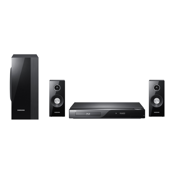
2.1CH Blu-ray Home Theater System
HT-C5200
Refer to the service manual in the GSPN (see the rear cover) for the more information.
2.1CH Blu-ray
Home Theater System
Model Name : HT-C5200
Model Code : HT-C5200/EDC
Speaker
PS-C5200
Front
PS-FC5200
Subwoofer
PS-WC5200
Manual
1. Precaution
2. Product Specification
3. Disassembly & Reassembly
4. Troubleshooting
5. Exploded View & Part List
6. PCB Diagram
7. Schematic Diagram
CONTENTS
Advertisement
Table of Contents

Related Manuals for Samsung PS-WC5200


Summarization of Contents
1. Precaution
1-1 Safety Precautions
Safety instructions for servicing the unit and protecting against hazards.
1-2 Servicing Precautions
Instructions and precautions to follow during the servicing of the unit.
1-3 Precautions for Electrostatically Sensitive Devices (ESDs)
Techniques to reduce component damage caused by static electricity.
7. Schematic Diagram
7-1 Overall Block Diagram
Explains the overall signal flow and component interaction within the system.
7-2 FRONT
Shows the component layout and pin connections for the FRONT PCB.
7-4 AMP-1
Provides the schematic for the AMP section, detailing power and audio paths.
7-10 HDMI MICOM
Details the schematic for the HDMI MICOM and related components.
7-13 NAND FLASH / CLOCK / BBS / JTAG
Provides the schematic for NAND Flash, clock, BBS, and JTAG interfaces.
7-16 7630 POWER / DECOUPLING
Provides the schematic for power supply and decoupling circuits.
7-19 FRONT MICOM
Provides the schematic for the front panel microcontroller (MICOM).
7-22 DC-DC POWER
Provides the schematic for the DC-DC power supply circuits.
7-24 SMPS
Shows the schematic for the Switched-Mode Power Supply (SMPS).
2. Product Specification
2-1 Product Feature
Lists the key features and capabilities of the HT-C5200 system.
2-2 Specifications
Details the electrical and physical specifications of the HT-C5200.
2-3 Specifications Analysis
Compares specifications across different Samsung models (HT-C5200, HT-BD3252, HT-BD1250).
2-4 Accessories
Lists the supplied accessories with their item codes and remarks.
3. Disassembly & Reassembly
3-1 Overall Disassembly & Reassembly
Provides step-by-step instructions for disassembling the main unit.
3-2 DECK Disassembly & Reassembly
Details the disassembly and reassembly procedures for the disc deck mechanism.
4. Troubleshooting
4-1 Checkpoints by Error Mode
Provides steps to check and diagnose issues based on error modes.
4-2 Initialization & Upgrade Methods
Explains methods for initializing the system and updating firmware.
4-3 Buyer-Region Code Setting Method
Describes how to set the region code after replacing the main PBA.
5. Exploded View & Part List
5-1 Product Exploded View
Illustrates the exploded view of the main product assembly with part labels.
5-2 DECK Exploded View
Shows the exploded view of the disc deck mechanism assembly.
5-3 Speaker System
Details the speaker system components and their connections.
5-4 Electrical Part List
Lists electrical components with part numbers, specifications, and quantities.
6. PCB Diagram
6-1 Wiring Diagram
Shows the overall wiring connections between different PCBs and connectors.
6-2 FRONT PCB Top
Illustrates the component layout and pin connections for the FRONT PCB.
6-4 AMP PCB Top
Shows the component layout for the AMP PCB.
6-6 MAIN PCB Top
Shows the component layout for the MAIN PCB's top side.
6-8 SMPS PCB Top
Shows the component layout for the SMPS PCB's top side.
Need help?
Do you have a question about the PS-WC5200 and is the answer not in the manual?
Questions and answers