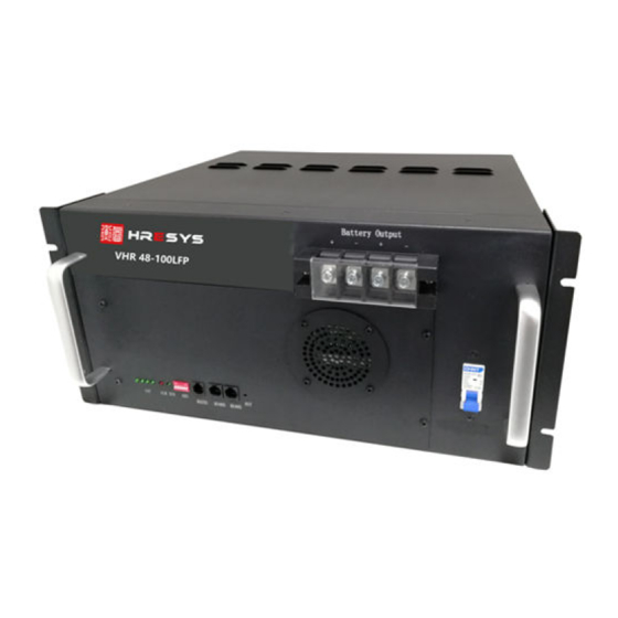
Summarization of Contents
Unboxing and Initial Inspection
Manual Review
Read this manual thoroughly before commencing the installation process.
Package Integrity Check
Inspect the package for any visible damage upon receipt and report to the supplier immediately if found.
Professional Installation Requirement
This device must be installed and operated exclusively by qualified and professional personnel.
Preparation for Installation
Optimal Placement Conditions
Install batteries away from direct sunlight and heat sources, ensuring good ventilation for heat dissipation.
Environmental Suitability
Ensure the installation area has clean air and low humidity; avoid placing heavy items on any cables.
Tool and Material Requirements
Utilize appropriate tools and materials, strictly using only those with insulated handles for safety.
Battery Module Installation Steps
Step 1: Secure Battery Shelf
Firmly secure the battery shelf into the cabinet using M6 bolts.
Step 2: Place Module in Cabinet
Place the battery module onto the shelf and push it into the cabinet.
Step 3: Secure Module Front Panel
Secure the module's front panel to the 19" rails using M6 bolts after placement.
Step 4: Install Remaining Modules
Install subsequent battery modules following the same steps and ensure they are fixed firmly.
Step 5: Install Stand-off Insulators
Install stand-off insulators on the cabinet's top panel and fix output busbars to them.
Step 6: Connect Positive Cables
Connect positive terminals of modules to positive output cables, routing them to the top busbar.
Step 7: Connect Negative Cables
Connect negative terminals of modules to negative output cables, routing them to the top busbar.
Step 8: Repeat Connections
Repeat steps 6 and 7 for all modules installed in the rack.
Step 9: Connect Communication Lines
Connect communication lines between modules, reserving one for PCS connection.
Step 10: Connect Earthing Cable
Connect each module's front panel to the 19" rack using an earthing cable.
Step 11: Installation Complete
Final confirmation that the installation process has been successfully completed.


Need help?
Do you have a question about the VHR TL48100LFP and is the answer not in the manual?
Questions and answers