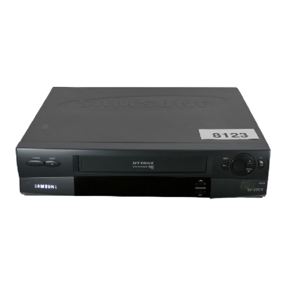
Table of Contents
Advertisement
Quick Links
Advertisement
Table of Contents

Summarization of Contents
General Information
Also Covers
Lists other compatible models for the service manual.
Matrix
A table listing items and corresponding model numbers and pages.
Recommended Safety Parts
Lists critical components for safe replacement and repair.
Reference Information
Servicing Jigs and Special Tools
Details specific tools and jigs required for service.
How to Connect X-5 chassis jig
Step-by-step instructions for connecting the X-5 chassis jig.
Product Specifications and Comparison Chart
Product Specifications
Details the operational and technical parameters of the device.
Comparison Chart
Compares functional features across different model variants.
Disassembly and Reassembly
Cabinet Assembly
Instructions for removing the outer cabinet components.
Bottom cover removal
Details the procedure for removing the bottom protective cover.
Ass'y Front Panel removal
Instructions for detaching the front panel assembly.
Ass'y Function-Timer removal
Details the procedure for removing the function-timer assembly.
Chassis removal
Instructions for removing the main chassis assembly.
Circuit Board Locations
Identifies the positions of main circuit boards within the chassis.
Alignment and Adjustment
Reference
Background information on alignment procedures.
Mechanical Adjustment
Details physical adjustments required for optimal performance.
X-Point(Tracking center) adjustment
Procedure for adjusting the tracking center alignment.
Normal Remote Control Assembly Adjustment
Details adjustment using a standard remote control.
Electrical Adjustment
Details electronic adjustments and calibration steps.
Head S/W Adjustment
Procedure for adjusting the Head S/W point.
RF AGC Adjustment
Details the Radio Frequency Automatic Gain Control adjustment.
Timing Chart of Program S/W
Illustrates the timing relationships of the program switch signals.
Exploded View and Parts List
Cabinet Assembly
Exploded view of the cabinet and its constituent parts.
Mechanical Parts (Top Side)
Lists and illustrates mechanical components found on the top side.
Mechanical Parts (Bottom Side)
Lists and illustrates mechanical components found on the bottom side.
Housing Assembly
Exploded view of the device's housing components.
Electrical Parts List
SMPS/POWER PARTS
Lists components specific to the power supply unit.
SYSTEM CONTROL/SERVO PARTS
Lists components for system control and servo functions.
AUDIO/VIDEO PARTS
Lists components related to audio and video processing.
IF PARTS
Lists components for the Intermediate Frequency (IF) section.
Block Diagrams
Overall Block Diagram
A high-level overview of the system's main functional blocks.
System Control
Details the system control and MCU block functions.
Video
Illustrates the video signal processing path.
Schematic Diagrams
Block Identification of Main PCB
Identifies functional blocks on the main PCB.
S.M.P.S/Power
Schematic of the Switched-Mode Power Supply and power circuits.
System Control/Servo
Schematic for system control IC and servo motor driver circuits.
Audio/Video (SV-A20GK/SV-A40GK/SV-200G/SV-205G)
Schematic for Audio/Video processing.
Audio/Video (SV-A60GK/SV-A80GK/SV-400G/SV-405G)
Schematic for Audio/Video processing.
IF
Schematic of the Intermediate Frequency (IF) tuner stage.
I/O
Schematic for Input/Output circuits including SCART and other connectors.
VPS
Schematic for the Video Programming System (VPS) circuit.
Function-Timer (SV-A20GK/SV-A60GK/SV-200G/SV-400G)
Schematic for the function-timer board.
Function-Timer (SV-A40GK/SV-A80GK/SV-205G/SV-405G)
Schematic for the function-timer board.
Remote-Control
Schematic of the remote control interface and associated components.


Need help?
Do you have a question about the SV-A40 IK and is the answer not in the manual?
Questions and answers