Table of Contents
Advertisement
ELECTRONIC SERVICE MANUAL
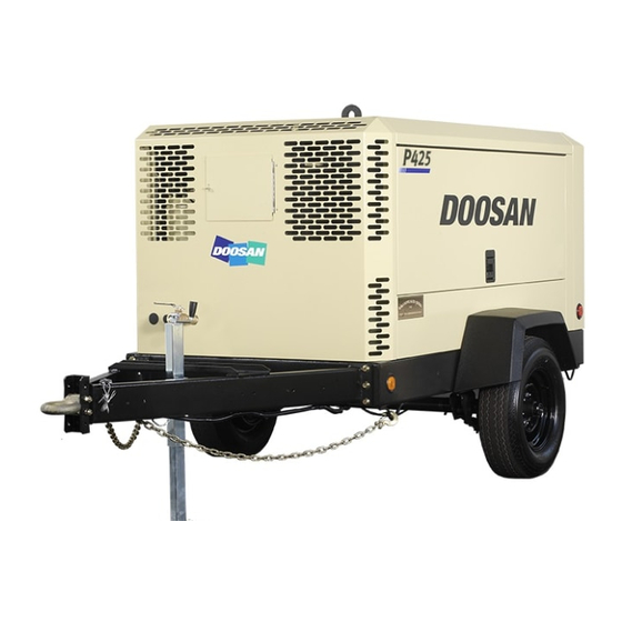
P425WIR (7/120)
XP375WIR (9/110)
HP350WIR (10/105)
HP350WIR (14/85)
P600WIR (7/170)
HP450WIR (10/125)
VHP400WIR (14/115)
COMPRESSOR MODELS
Doosan purchased Bobcat Company from Ingersoll-Rand Company in
2007. Any reference to Ingersoll-Rand Company or use of trademarks,
service marks, logos, or other proprietary identifying marks belonging
to Ingersoll-Rand Company in this manual is historical or nominative
in nature, and is not meant to suggest a current affiliation between
Ingersoll-Rand Company and Doosan Company or the products of
either.
Doosan Infracore Portable Power
1293 Glenway Drive
Statesville, N.C. 28625
www.doosanportablepower.com
Book: 23227143 (6-09) Rev B
Revised (10-12)
Codes:
C46 (C95)
C48 (C94)
C47 (C96)
C47 (D17)
C54 (D18)
C55 (D19)
C56 (D20)
Advertisement
Chapters
Table of Contents
Troubleshooting

Summarization of Contents
General Information
Operational Theory
Explains how the system monitors and controls discharge air pressure.
WEDGE Controller Functionality
Details the function and components of the WEDGE controller.
Electrical System Overview
Outlines the wiring harnesses and electrical devices used in the machine.
Operating Controls and Instruments
Control Panel Devices
Describes the function of each control panel instrument and indicator light.
Model-Specific Operational Information
Outlines startup, load, and idle sequences for different compressor models.
Settings
Reading and Setting Display Units
Guides on how to view and change display unit settings.
Wedge Service Diagnostic Display
Explains how to access and interpret machine parameters via the diagnostic display.
Machine Models List
Provides a list of machine models and their corresponding IDs for system configuration.
Diagnostic Code Descriptions
Compressor Diagnostic Display Codes
Lists and defines various diagnostic codes related to compressor malfunctions.
John Deere Engine Diagnostic Codes
Details diagnostic codes specific to John Deere engines used in the machines.
Troubleshooting
Basic Troubleshooting Steps
Outlines fundamental steps for diagnosing and resolving issues.
Troubleshooting Flow Chart
Provides a visual guide for systematic troubleshooting of common problems.
Compressor Code 1: Low Engine Speed
Explains and provides troubleshooting steps for low engine speed errors.
Compressor Code 4: Low Fuel Level
Explains and provides troubleshooting steps for low fuel level conditions.
Electrical Circuits
Engine Start Circuit
Details the circuit responsible for engaging the engine starter.
Air Filter Restriction Switch Circuit
Explains the circuit for monitoring air filter restriction.
System Schematics & Wiring Diagrams
John Deere Engine Harness Schematic
Illustrates the wiring connections for John Deere engines.
Electrical Component Locations
Component Location Diagrams
Shows visual representations of where electrical components are located on the machine.
Electrical Parts List
Electrical Component Parts
Lists electrical components with their part numbers and descriptions.
Harness Connector Information
Connector and Part Number Details
Provides a list of connectors, their manufacturers, and part numbers.
Tools and Repair Kits
Service Tools and Repair Kits
Lists recommended special service tools and repair kits for maintenance.
Connector Repair Kits
Lists kits specifically for repairing electrical connectors.
Deutsch Crimp Tool HDT-48-00 Instructions
Provides instructions for using the Deutsch HDT-48-00 crimp tool.
AMP Crimp Tool 58440-1 Instructions
Offers guidance on using the AMP Crimp Tool 58440-1.
Recommended Spare Parts
Spare Parts List
Lists essential spare parts with quantities and part numbers.
Software Information
Software Updates
Information on obtaining the latest software revisions for the product.


Need help?
Do you have a question about the D20 and is the answer not in the manual?
Questions and answers