Table of Contents
Advertisement
Quick Links
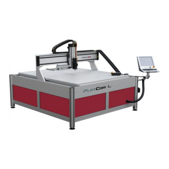
FlatCom, Series L
FlatCom, Series XL
FlatCom, Series M
Assembly Instruction for CNC base machinery
(partly completed machinery)
Operating Instruction for CNC machinery
(complete machinery)
Type: FlatCom ®
Series M (20, 30, 40, 50)
Series L (150, 250, 300)
Series XL (102, 142)
isel Germany AG
Bürgermeister-Ebert-Straße 40 D-36124 Eichenzell Tel.: (06659) 981-0 Fax: -776
Advertisement
Table of Contents

Related Manuals for Isel FlatCom M Series


Summarization of Contents
About this Manual
Used Shortcuts
Lists abbreviations used in the manual.
Used Symbols
Explains important symbols for warnings and information.
Safety Instructions Overview
Pre-operation Safety Checks
Emphasizes reading safety instructions before operation and making changes.
Copyright and Manufacturer Information
CE Marking Status Explained
Explains CE marking for complete and partly completed machines.
Manufacturer Contact Details
Provides manufacturer's address and contact information.
1 Introduction to FlatCom Machines
Prerequisites for Manual Use
States knowledge and terminology prerequisites for using the manual.
Operator Software Identification
Specifies the required operator software versions.
2 Intended Use and Misuse of FlatCom
CNC Machine vs. Base Machine Definitions
Differentiates between CNC machines and CNC base machines.
CNC Machine Application Scope
Defines an "isel CNC machine" based on application and tool.
CNC Base Machine Definition
Defines an "isel CNC base machine" as partly completed.
3 Safety Information
Enclosure and Safety Interlocks
Discusses the machine enclosure, sliding doors, and safety interlocks.
Partly Completed Machinery Safety
Covers safety for partly completed machines and operator responsibility.
Workpiece Clamping and Emergency Halt
Emphasizes secure clamping and explains the Emergency Halt switch.
4 Scope of Delivery / Distribution State
Standard Scope of Delivery Components
Lists the components included in the standard delivery package.
Control Software Included in Delivery
Details the pre-installed control software and backup procedures.
4.2 Delivery Status from Factory (Quality Management)
Circular Form Measuring System QC10
Explains the use of the Renishaw QC10 for accuracy verification.
Machine Error Recognition Methods
Describes how recognized circle forms indicate machine errors.
Position Accuracy Testing Methods
Laser Interferometer Renishaw XL80 Use
Describes the use of the Renishaw XL80 for position accuracy testing.
Velocity Profile Analysis for Axes
Explains how velocity profiles are analyzed for axis motion.
5 Installation and Connection of the CNC Machine
Space Requirements for Installation
Provides diagrams and requirements for machine installation space.
5.2 Transport of the CNC Machine
Safe Transport and Handling Procedures
Details safe transport, lifting, and handling precautions.
5.3 Putting Up the CNC Machine
Machine Alignment and Leveling
Explains axis alignment and how to level the machine using adjustable feet.
Professional Installation Service Offer
Offers a service for measuring and calibrating the machine on-site.
5.4 Enclosure Features
CNC Machine Enclosure and Interlocks
Describes the enclosure, panes, and safety interlocks on CNC machines.
CNC Base Machine Protective Measures
Outlines requirements for mounting protective measures on base machines.
5.5 Cabling and Compressed Air Connection
Compressed Air Requirements for Accessories
Information on air pressure and consumption for accessories.
6 Initial Operation
Control Panel and Operating Elements
Shows the CNC control panel and its operating elements.
Coordinate System and Zero Point Definition
Explains the machine's coordinate system and how to define the workpiece zero point.
Axis Assignment and Reference Points
Assignment of Motion Axes
Details axis assignments for flatbed and portal machinery.
Reference Point and Home Position Setup
Explains the machine's reference point and home position setup.
Workpiece Clamping and Machine Types
Workpiece Mounting and Clamping Guidelines
Advises on using safe clamping tools for workpieces.
Portal vs. Flatbed Machinery Axis Motion
Contrasts Y-axis motion in portal and flatbed machinery.
6.2 Operation Modes
AUTO Mode (Processing)
Explains automatic processing mode with door/cover interlock.
TEST Mode (Setup)
Describes test mode for setup, allowing open door operation with restrictions.
6.3 Cover Lock, Unlock, and Interlock
Cover Interlock Functionality
Details the cover interlock as a safety feature.
Standstill Monitoring for Axes
Explains how standstill monitoring enables cover unlocking in AUTO mode.
Cover Control and Manual Unlock
Safety Interlock Sensor and Actuator
Describes sensor and actuator functions for cover lock/unlock.
Manual Cover Unlock Procedure
Provides steps for manually unlocking the door/cover using a triangular key.
6.4 CNC Operating Panel
PC Boot/Shut Down Button
Explains the button for powering the control PC on and off.
Front Panel Operating Elements
Details the operating elements on the CNC control panel and hand control unit.
Operating Panel Buttons Explained
Emergency Stop and Fault Indicators
Explains the emergency stop function and fault indicators.
Power, Start, and Stop Buttons
Explains the function of power, start, and stop buttons for program execution.
Control Buttons and Mode Selection
Cover Button and Program Continuation
Details the cover button's role and continuing program execution.
ACK Button and Mode Selection Switch
Explains ACK button use and mode selection switch for AUTO/TEST.
Operation Mode Alternation Safety
AUTO to TEST Mode Transition
Describes mode alternation from AUTO to TEST and spindle behavior.
TEST to AUTO Mode Transition
Describes mode alternation from TEST to AUTO and spindle behavior.
6.4.3 CNC Operating Panel - Left Side
USB Connectors for Data Transfer
Explains the use of USB ports for data transfer and dongles.
6.5 CNC Control Software Installation
Software Options: ProNC and Remote
Presents the choice between ProNC and Remote control software.
Software Installation Guidance
Directs users to specific chapters for software installation.
7 Accessories
Available Machine Accessories List
Lists various optional accessories for the CNC machines.
Compressed Air Requirements for Accessories
Information on air pressure and consumption for accessories.
Accessory Details
Dust Extraction System Information
Details the optional dust extraction system.
Tool Changer System Functionality
Explains the tool changer, its air pressure, and length measurement.
8 Technical Support and Sale
Contact Information and Services
Provides contact details for technical support and sales, plus company information.
9 Cleaning, Lubrication and Maintenance
General Cleaning Procedures
Outlines methods for cleaning the machine and its components.
Lubrication Guidelines and Intervals
Specifies lubrication intervals, types of grease, and axis lubrication points.
Grease Properties and Lubrication Preparation
Properties of isel Special Grease
Lists the characteristics and classification of the special grease.
Lubrication Preparation Steps
Details the safety steps before starting axis lubrication.
9.2.3 Lubrication of the X Axis
X Axis Grease Nipple Locations
Shows where to find and access the grease nipples for the X axis.
9.2.4 Lubrication of the Y Axis
Y Axis Grease Nipple Locations
Illustrates the location of grease nipples for the Y axis.
9.2.5 Lubrication of the Z Axis
Z Axis Grease Nipple Location
Shows the location of the grease nipple for the Z axis.
10 Faults
Troubleshooting Power and Software Issues
Lists reasons and solutions for power, software, and servo motor faults.
Working Spindle and Frequency Converter Issues
Explains how to resolve working spindle and frequency converter issues.
11 Remote Diagnosis
Remote Diagnosis Setup Process
Details the steps for establishing remote diagnosis via the internet.
12 Technical Data of CNC Machine / CNC Base machine
Clamping Area and Traversing Range FlatCom Series M
Provides technical dimensions for FlatCom Series M models.
12.2 Clamping Area and Traversing Range FlatCom Series L
FlatCom Series L Dimensions
Shows technical dimensions for FlatCom Series L models.
12.3 Clamping Area and Traversing Range FlatCom Series XL
FlatCom Series XL Dimensions
Provides technical dimensions for FlatCom Series XL models.
Machine Variants and Certifications
FlatCom Base Machine Variants
Describes the two variants of the FlatCom base machine.
FlatCom Machine Certification
Explains the CE mark and Declaration of Conformity for FlatCom machines.
12.4 Mechanical Values / Electrical Values
Weight, Guides, and Drive Elements
Lists machine weights and details about guides and drive elements.
Control Cabinet and Sound Pressure
Details control cabinet specs and sound pressure levels.
13 Declaration of Conformity or Declaration of Incorporation?
Machinery vs. Partly Completed Machinery Definitions
Defines machinery types based on the directive and tool usage.
13.1 Declaration of Conformity for Machinery
EC Declaration of Conformity Details
Presents the EC Declaration of Conformity for CNC machines.
13.2 Declaration of Incorporation for Partly Completed Machinery
Declaration of Incorporation Details
Presents the Declaration of Incorporation for partly completed machines.
14 Exploded Views / Spare Parts Lists
FlatCom 20 Exploded View and Parts
Shows exploded view and lists spare parts for the FlatCom 20.
Spare Parts List for FlatCom 20
FlatCom 20 Parts Breakdown
Lists spare parts for the FlatCom 20 with article numbers.
FlatCom 30 Exploded View
Exploded View of FlatCom 30
Displays an exploded view of the FlatCom 30 base machine.
Spare Parts List for FlatCom 30
FlatCom 30 Parts Breakdown
Lists spare parts for the FlatCom 30 with article numbers.
FlatCom 40 Exploded View
Exploded View of FlatCom 40
Shows exploded view and lists spare parts for the FlatCom 40.
Spare Parts List for FlatCom 40
FlatCom 40 Parts Breakdown
Lists spare parts for the FlatCom 40 with article numbers.
FlatCom 50 Exploded View
Exploded View of FlatCom 50
Displays an exploded view of the FlatCom 50 base machine.
Spare Parts List for FlatCom 50
FlatCom 50 Parts Breakdown
Lists spare parts for the FlatCom 50 with article numbers.
15 Bibliography
Referenced Documentation List
Lists referenced operating instructions, programming guides, and directives.
16 Index
Index Entries A-M
Provides an alphabetical index of topics covered in the manual.
Index Continuation
Index Entries N-W
Continues the alphabetical index of topics covered in the manual.
Final Index Entries
Index Entries (Weight, USB, etc.)
Lists final index entries including weight and USB related topics.
Need help?
Do you have a question about the FlatCom M Series and is the answer not in the manual?
Questions and answers