Table of Contents
Advertisement
P.O. Box 2758
Windsor, Nova Scotia, B0N 2T0
Phone: 902-798-2261 Fax: 902-798-2557
www.nu-airventilation.com
Email: nuair@nu-airventilation.com
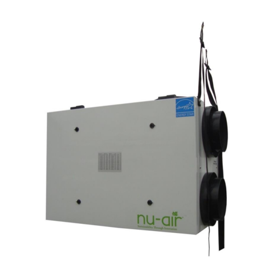
Now Featuring the Nu-Air EZ System.
1. EZ Level suspension straps.
2. EZ Balance pressure ports to measure
and balance air flows.
Windsor SERIES
OPERATING, MAINTAINING & INSTALLING YOUR HEAT RECOVERY
VENTILATOR
FOR MODELS NU145, NU165, NU205, MANUFACTURED MAY 2015 ONWARD
* LEAVE THIS DOCUMENT WITH THE HOMEOWNER
Specifications, dimensions and ratings may change without notice
.
as a result of ongoing product development and improvements
Rev. 6.1 November 1, 2016
Advertisement
Table of Contents

Related Manuals for Nu-Air Windsor NU205


Summarization of Contents
System Function and Operating Tips
Operating Modes
Details various operational modes like standby, low speed, high speed, and timed cycles.
Installation Guide
Installation Supplies
Lists standard items included with the HRV unit for installation.
Installer Responsibilities
Outlines installer duties for proper system performance and code compliance.
System Sizing
Guidance on calculating Total Ventilation Capacity (TVC) for residential applications using the Room Count Method.
Installation System Options
Describes three common and approved methods for installing the Nu-Air HRV system.
Fully Ducted System
Details the system using an independent duct for supply and exhaust air, controlled independently.
Extended Exhaust System
Uses HRV with a forced air furnace system, supplying air to return duct and transferring stale air.
Extended System Continuous Ventilation
Discusses continuous ventilation with the furnace fan potentially interlocked to the HRV.
Extended System Intermittent Ventilation
Covers intermittent HRV operation with furnace fan interlocked for supply air distribution.
Simplified System
Utilizes furnace return plenum for supply and exhaust air, with specific connection requirements.
Ducting to the Outside
Provides guidelines for connecting the HRV to external air intake and exhaust hoods.
Weather Hood Installation
Step-by-step instructions for installing weather hoods, including duct connection and sealing.
Weather Hood Placement
Specifies minimum separation distances and height requirements for fresh air and exhaust hoods.
Mounting and Noise Control
Guidance on mounting the HRV unit using anti-vibration straps and considerations for noise reduction.
Hanging Strap Installation
Illustrates the process of installing hanging straps for unit mounting and leveling.
Connecting to Other Equipment
Details permissible interconnections with forced air furnace systems for residential applications.
Ductwork Guidelines
Best practices for designing and installing duct systems, including material, joints, and support.
5th Port Ducting Strategies
Presents three options for ducting the 5th port for recirculation and defrost strategies.
Drain Connections
Instructions for installing the condensate drain assembly, including P-trap formation.
Single-Drain Unit P-Trap
Guidance on forming a P-shape for the drain hose on single-drain units to prevent kinks.
Furnace Interlock
Explains the mandatory and recommended interconnections between the HRV and the furnace blower.
Interlock Jumper Settings
Details jumper settings for interlock operation at any HRV speed or high speed only.
Balancing Air Flows
Essential procedures for balancing supply and exhaust air flows for optimal HRV performance.
Magnehelic Gauge Balancing
Step-by-step guide for balancing air flows using a Magnehelic gauge and flow grid.
Manometer Balancing
Instructions for using a differential pressure manometer or gauges with pressure ports for balancing.
Adjusting Fan Speed for Balancing
Procedure for adjusting fan speeds to achieve balanced air flows and meet capacity requirements.
Control Options and Wiring
ES Series Controls (12 VDC)
Details the ES Tx and Mx controls, including features, functions, and wiring.
ES Controls Functions
Table outlining the functions of various ES Series controls like ES-T1, ES-M1, ES-M2, ES-M3, ES-M4.
ES Lumina Control
Description of the ES Lumina control unit, its features, functions, and compatibility.
Wiring ES Series Controls
Instructions for wiring ES Series controls to the HRV/ERV terminal block, including critical warnings.
Windsor Series & 24V Controls
Overview of Nu-Air's 24 VAC Windsor Series controls and other compatible 24V controls.
Wiring Windsor Series Controls
Procedure for connecting Windsor Series controls and other 24 VAC controls to the terminal block.
DSTAT-1 Control Wiring
Specific wiring instructions and jumper options for the DSTAT-1 dehumidistat control.
Win-1 Control Wiring
Wiring diagram and operating modes for the Win-1 control unit.
Win-20 Control Wiring
Wiring details and compatibility for the Win-20 timer control, including options for continuous low speed.
Remote 2-Wire Switching
Instructions for connecting a remote 2-wire switch, including jumper options for operation modes.
Status LEDs and Operation Modes
Explanation of status LED indicators and their corresponding unit operating modes.
Maintenance
Filter Maintenance
Guidance on cleaning and replacing filters to maintain ventilation efficiency.
Fan Maintenance
Instructions for cleaning fan blades and interior surfaces during filter maintenance.
Condensate Drain Maintenance
Procedure for cleaning the condensate drain pan and tubing twice yearly.
Heat/Energy Recovery Core Cleaning
Instructions for removing and cleaning the HRV core annually.
Exterior Hood Maintenance
Regular checks and cleaning of exterior vents to prevent obstructions.
Grills and Ductwork Cleaning
Cleaning grills and inspecting ductwork for punctures, with repair instructions.
Electrical Schematics
NU165 Electrical Schematic
Wiring schematic for the NU165 model, showing autotransformer, motors, and control board connections.
NU145 Electrical Schematic
Wiring schematic for the NU145 model, detailing its electrical components and connections.
NU205 Electrical Schematic
Wiring schematic for the NU205 model, illustrating its electrical components and connections.
Warranty Information
Warranty Limitations
Outlines conditions not covered by the warranty, such as improper installation or lack of maintenance.
Need help?
Do you have a question about the Windsor NU205 and is the answer not in the manual?
Questions and answers