Table of Contents
Advertisement
www.nu-airventilation.com
* LEAVE THIS DOCUMENT WITH THE BUILDING OWNER
Document # CSM001 Revision Date: August 9, 2016
P.O. Box 2758 Windsor, Nova Scotia, B0N 2T0
Ph. 902-798-2261
COMPLIANT SERIES
H
R
V
/
E
R
V
H
R
V
/
E
R
V
N
U
0
8
2
0
/
N
U
2
N
U
0
8
2
0
/
N
U
2
Specifications, dimensions and ratings may change without notice
as a result of ongoing product development and improvements
Page 1 of 48
Fax: 902-798-2557
email: nuair@nu-airventilation.com
P
R
O
D
U
C
T
M
A
N
P
R
O
D
U
C
T
M
A
N
0
3
5
/
N
U
2
5
4
0
/
0
3
5
/
N
U
2
5
4
0
/
U
A
L
U
A
L
N
U
1
0
3
0
N
U
1
0
3
0
.
Advertisement
Table of Contents

Related Manuals for Nu-Air NU0820


Summary of Contents for Nu-Air NU0820
- Page 1 P.O. Box 2758 Windsor, Nova Scotia, B0N 2T0 Ph. 902-798-2261 Fax: 902-798-2557 www.nu-airventilation.com email: nuair@nu-airventilation.com COMPLIANT SERIES * LEAVE THIS DOCUMENT WITH THE BUILDING OWNER Specifications, dimensions and ratings may change without notice as a result of ongoing product development and improvements Document # CSM001 Revision Date: August 9, 2016 Page 1 of 48...
-
Page 2: Table Of Contents
ERV ..............................22 PERFORMANCE DATA – FANS ........................23 NU0820 HRV ..........................23 NU0820 HRV Face and By Pass ....................23 NU0820 ERV ..........................24 NU0820 ERV Face and By Pass....................24 Document # CSM001 Revision Date: August 9, 2016... - Page 3 NU1030 HRV ..........................25 NU1030 HRV Face and By Pass ....................25 NU1030 ERV ..........................26 NU1030 ERV Face and By Pass....................26 NU2035 & NU2540 HRV ......................27 7.10 NU2035 & NU2540 Face and By Pass HRV ............... 27 7.11 NU2035 and NU2540 ERV ....................
-
Page 4: About The H/Erv
1 ABOUT THE H/ERV The heat recovery ventilator (HRV) provides fresh air to a conditioned space while exhausting an equal amount of stale air. Heat energy is transferred from one air stream to the other within a non-contact cross flow heat exchanger. ERV models transfer latent energy (moisture) from the higher to lower air stream. -
Page 5: Product Selection
2 PRODUCT SELECTION Unit Options NU0820 NU2035 NU1030 NU2540 800 - 2000 - 1000 - 2000 - Capacity (cfm range) 2000 4000 3000 4000 Indoor Location Outdoor None Exhaust Only (temperature on/off) Defrost Timed Exhaust(temperature on/timed off) Recirculation *Face and by Pass... -
Page 6: Nomenclature
3 NOMENCLATURE NU0820 NU0820 Port and Defrost Configurations 1 - Outside Air (OA) 2 - Supply Air (SA) 3 - Return Air (RA) 4 - Exhaust Air (EA) Defrost Options A,E Defrost Options B,F Defrost Options C,G Defrost Options D,H... -
Page 7: Nu1030, Nu2035, Nu2540
NU1030, NU2035, NU2540 NU1030 & NU2540 Not Available in these models NU2035 Not Available in these models 1 - OA 2 - SA 3 - RA 4 - EA Document # CSM001 Revision Date: August 9, 2016 Page 7 of 48... -
Page 8: Sample Specification
4 SAMPLE SPECIFICATION GENERAL System description: Packaged Heat (Energy) Recovery Ventilator capable of transferring sensible (sensible and latent) energy designed to be used as a standalone ventilation system or as part of an engineered HVAC system with flat plate, cross flow heat exchanger integral to the unit. - Page 9 Blowers Blowers shall be FC DWDI, dynamically balanced and operate at not more than 1500 rpm. Internal vibration isolation is not required. Blower housing shall be galvanized steel. Motors Motors shall be continuous duty, permanently lubricated with a service factor of 1.15, matched to the fan load and required voltage and phase.
- Page 10 Both defrost and run cycles shall be field adjustable via the unit’s control. Recirculation Defrost (NU0820) – a temperature sensor initiates defrost when outside air is cold enough to freeze condensate. The exhaust fan shuts down, the recirculation damper opens, the gravity and motorized back draft dampers close.
-
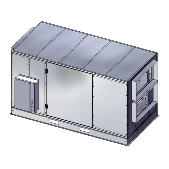
Page 11: Dimensional Data
24VAC by moving a jumper. Roof Curb A 14” roof curb shall be supplied by the equipment manufacturer. 5 DIMENSIONAL DATA NU0820 Document # CSM001 Revision Date: August 9, 2016 Page 11 of 48... - Page 12 Document # CSM001 Revision Date: August 9, 2016 Page 12 of 48...
-
Page 13: Nu1030
NU1030 Document # CSM001 Revision Date: August 9, 2016 Page 13 of 48... -
Page 14: Nu2035
NU2035 Document # CSM001 Revision Date: August 9, 2016 Page 14 of 48... -
Page 15: Nu2540
NU2540 Document # CSM001 Revision Date: August 9, 2016 Page 15 of 48... -
Page 16: Nu0820 Curb
NU0820 Curb Document # CSM001 Revision Date: August 9, 2016 Page 16 of 48... -
Page 17: Nu1030 And Nu2540 Curb
NU1030 and NU2540 Curb Document # CSM001 Revision Date: August 9, 2016 Page 17 of 48... -
Page 18: Performance Data - Effectiveness
6 PERFORMANCE DATA – EFFECTIVENESS NU0820 & NU1030 6.1.1 HRV NU0820 Poly Core 1000 1500 2000 2500 3000 Total Effectiveness Summer Sensible Effectivness Winter AHRI Rating Point 75% Ratings outside the scope of the AHRI Energy Recovery Ventilation Certification Program AHRI Rating Point 100% 6.1.2 ERV... -
Page 19: Nu0820 Face And By Pass
NU0820 Face and By Pass 6.2.1 HRV NU0820 Poly Core, Face and by-pass 1000 1200 1400 Total Effectiveness Summer Sensible Effectivness Winter AHRI Rating Point 75% Ratings outside the scope of the AHRI Energy Recovery Ventilation Certification Program AHRI Rating Point 100% 6.2.2 ERV... -
Page 20: Nu1030 Face And By Pass
NU1030 face and by Pass 6.3.1 HRV NU1030 Face and By Pass 1000 1200 1400 1600 1800 Total Effectiveness Summer Sensible Effectivness Winter AHRI Rating Point 75% Ratings outside the scope of the AHRI Energy Recovery Ventilation Certification Program AHRI Rating Point 100% 6.3.2 ERV NU1030 ERV Model no. -
Page 21: Nu2035 & Nu2540
NU2035 & NU2540 6.4.1 HRV NU2035 & NU2540 1000 1500 2000 2500 3000 3500 4000 4500 Total Summer Sensible Winter Ratings outside the scope of the AHRI Energy AHRI Rating Point 75% Recovery Ventilation Certification Program AHRI Rating Point 100% 6.4.2 ERV NU2035 &... -
Page 22: Nu2035 & Nu2540 Face And By Pass
NU2035 & NU2540 Face and By Pass 6.5.1 HRV NU2035 & NU2540 Face and by Pass 1000 1500 2000 2500 3000 Total Effectiveness Summer Sensible Effectivness Winter AHRI Rating Point 75% Ratings outside the scope of the AHRI Energy Recovery Ventilation Certification Program AHRI Rating Point 100% 6.5.2 ERV Model no. -
Page 23: Performance Data - Fans
1900 0.62 924 0.75 1030 0.89 1129 1.05 1233 1.12 1332 1.39 1424 2000 0.70 961 0.84 1063 0.99 1158 1.15 1256 1.32 1352 1.50 1443 NU0820 HRV Face and By Pass Motor Blower Data for Face and by-pass 0.25 0.50... -
Page 24: Nu0820 Erv
1800 0.69 1023 0.84 1130 0.99 1236 1.16 1336 1.32 1429 1900 0.80 1065 0.94 1166 1.10 1268 1.27 1365 1.45 1456 2000 0.92 1114 1.07 1209 1.24 1307 1.41 1401 1.60 1489 NU0820 ERV Face and By Pass Motor Blower Data for Face and by-pass 0.25 0.50... -
Page 25: Nu1030 Hrv
NU1030 HRV NU1030 HRV Face and By Pass Face and by pass core NU1030 Face and by Pass 0.25 0.50 0.75 1.00 1.25 1.50 CFM BHP RPM BHP RPM BHP RPM BHP RPM BHP RPM BHP RPM 800 0.10 582 0.17 771 0.26 917 0.34 1039 0.43 1142 0.52 1234... -
Page 26: Nu1030 Erv
NU1030 ERV NU1030 0.25 0.50 0.75 1.00 1.25 1.50 CFM BHP RPM BHP RPM BHP RPM BHP RPM BHP RPM BHP RPM 1000 0.18 700 0.27 864 0.37 999 0.47 1116 0.58 1219 0.69 1312 1100 0.21 734 0.32 892 0.42 1025 0.53 1140 0.65 1243 0.76 1336 1200 0.26 773 0.37 923 0.48 1052 0.60 1166 0.72 1268 0.85 1361 1300 0.31 810 0.42 953 0.55 1079 0.67 1191 0.80 1293 0.93 1385 1400 0.37 850 0.49 987 0.62 1109 0.75 1219 0.89 1319 1.03 1410... -
Page 27: Nu2035 & Nu2540 Hrv
NU2035 & NU2540 HRV NU2035 and NU2540 ESP = 0 ESP = 0.2 ESP = 0.6 ESP = 1.0 ESP = 1.2 ESP = 1.4 ESP = 1.75 ESP = 2.0 BHP RPM BHP RPM BHP RPM BHP RPM BHP RPM BHP RPM BHP RPM BHP RPM 2400 0.32 440 0.46 535 0.76 695 0.97 840 1.12... -
Page 28: Nu2035 And Nu2540 Erv
7.11 NU2035 and NU2540 ERV ESP = 0 ESP = 0.2 ESP = 0.4 ESP = 0.6 ESP = 0.8 ESP = 1.0 ESP = 1.2 ESP = 1.4 ESP = 1.5 BHP RPM BHP RPM BHP RPM BHP RPM BHP RPM BHP RPM 2000 0.37 617 0.46 700 0.56... -
Page 29: Electrical Data
9 ELECTRICAL DATA Motors – all units Electrical Schematics Several common electrical schematics are found below. The “as built” schematic for this unit was supplied with the equipment and is available from the factory by request. Document # CSM001 Revision Date: August 9, 2016 Page 29 of 48... - Page 30 Document # CSM001 Revision Date: August 9, 2016 Page 30 of 48...
- Page 31 Document # CSM001 Revision Date: August 9, 2016 Page 31 of 48...
- Page 32 Document # CSM001 Revision Date: August 9, 2016 Page 32 of 48...
- Page 33 Document # CSM001 Revision Date: August 9, 2016 Page 33 of 48...
- Page 34 Document # CSM001 Revision Date: August 9, 2016 Page 34 of 48...
- Page 35 Document # CSM001 Revision Date: August 9, 2016 Page 35 of 48...
- Page 36 Document # CSM001 Revision Date: August 9, 2016 Page 36 of 48...
- Page 37 Document # CSM001 Revision Date: August 9, 2016 Page 37 of 48...
- Page 38 Document # CSM001 Revision Date: August 9, 2016 Page 38 of 48...
- Page 39 Document # CSM001 Revision Date: August 9, 2016 Page 39 of 48...
-
Page 40: Installation
10 INSTALLATION The HRV motors are controlled and protected by a multi-starter which includes a disconnect switch. A Hand/Off/Auto selector is located on the starter for local or remote switching. 10.1 Remote Control Any dry contact switch closure may be used. Control voltage is 24 VAC. 10.1.1 INSTALLATION INSTRUCTIONS 10.1.1.1 Installer's Responsibilities... - Page 41 5. Apply the foam gasket to all top flanges of the curb forming a continuous, watertight seal. 6. With the HRV lifted, connect the drain hose to the spouts from underneath, feed the fresh air hose through the center curb member and tee into the exhaust drain.
-
Page 42: Connecting To Other Equipment
10.4 Connecting To Other Equipment If the HRV is used upstream of an air handler or similar equipment (e.g. fresh air into economizer section), the startup sequence must be HRV first followed by the air handler. If the air handler is started first, the HRV's fresh air fan will rotate backward and the motor may not be able to overcome the extra load causing the motor to over amp and potentially damage the blower wheel. -
Page 43: Balancing The System
10.6 Balancing The System Unless otherwise specified by the system designer, set up the HRV with balanced supply and exhaust air flows. The pulleys used on the supply and exhaust motors are a split type that allows some field adjustment of the fan rpm and corresponding air flow. Adjust the pulley in ½... -
Page 44: Commissioning And Start Up - Compliant Series
10.7 COMMISSIONING AND START UP - COMPLIANT SERIES Conduct a visual comparison of the HRV against the “As Built Drawing” available from the factory. Correct air flow configuration Correct Motors Installed Correct Pulleys Installed Correct Defrost Installed Correct Belts Installed also check tension, alignment and wear. - Page 45 At this point the unit is ready for final air balancing. The fan rpm and cfm have been factory set to as near as practical to the specified level. A certified air balancer will fine tune the air flows using dampers and adjusting the motor’s pulleys if needed.
-
Page 46: Maintenance
17x13.5x2 23.5x13.5x2 17x13.5x2 23.5x14.5x2 Quantity Nu-Air recommends a spare set of filters be ordered with the HRV for maintenance stores. b. FANS When cleaning the filters, take the opportunity to vacuum any interior surfaces including the fan blades. c. MOTORS The motors are equipped with permanently sealed and lubricated bearings d. -
Page 47: Exterior Hoods
from the HRV by sliding it forward on the guides. Observe proper orientation when replacing the core in the HRV. g. EXTERIOR HOODS Regularly check the outside vents and clean any obstructions such as grass, leaves or other debris. Do not replace the screen with mesh smaller than 1/4"... -
Page 48: Warranty
(2) years from the date of purchase. Nu-Air warrants its Compliant Series HRV core to be free from defects for a period of 15 years. Nu-Air warrants its Compliant Series ERV core to be free from defects for a period of 5 years.
Need help?
Do you have a question about the NU0820 and is the answer not in the manual?
Questions and answers