Advertisement
Quick Links
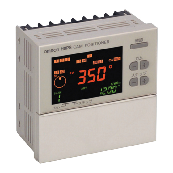
Cam Positioner
H8PS
This Compact Cam Positioner, Popular for Its
Ease-of-use, Now Comes with Even Better
Functions.
• Compact 8-, 16-, and 32-output Models available that are 1/4-
DIN size at 96 x 96 mm.
• High-speed operation at 1,600 r/min and high-precision settings
to 0.5° ensure widespread application.
• Highly visible display with backlit negative transmissive LCD.
• Advance angle compensation function to compensate for output
delays.
• Bank function for multi-product production (8 banks).
(H8PS-16@/-32@ models.)
• Speed display and pulse output.
• Approved standards: UL/CSA and EMC.
Features
Models with 8, 16, or 32 Outputs
The lineup includes Models with 32 outputs in a compact 1/4-DIN
size. Using the optional Parallel Input Adapter (Y92C-30) enables
expanding to up to 64 outputs for one encoder to support anything
from a simple positioning application to a large-scale system.
8-output Models
16-output Models 32-output Models
96 mm
96 mm
Simple Programming
The programming method is designed based on a one key-one
action concept for settings that could not be simpler. Both initial
settings and factory adjustments are effort-free.
Large, Backlit Negative LCDs
Large LCDs, red for the process value and green for set values, show
a wealth of operation information, making operating status visible at
a glance.
High Speed Up To 1,600 r/min
High Precision Up To 0.5° (at 720 Resolution)
High-speed, high-precision applications can be easily handled and
productivity increased.
Bank Function for Multi-product Production
Up to eight different programs can be registered in advance to
enable fast and easy switching between products (16/32-output
Models only).
USB Communications for Easy Setting from
a Computer
Optional Support Software can be used to enable programming from
a personal computer via USB communications. Programs can be
easily copied, saved, printed, and much more.
Refer to Safety Precautions for All Counters and
Safety Precautions on page 18 and 19.
Speed Display and Speed Alarm Output
Both the speed (rotations/minutes) and present angular position can
be displayed at the same time. Alarm outputs can be produced for
both upper and lower speed limits.
1
2
7
RUN
Present angular
position
Speed
Upper limit
STEP
CAM
Lower limit
Switchable
Upper limit
alarm output
1
2
7
Lower limit
RUN
alarm output
Speed
Present angular
position
CAM
STEP
Advance Angle Compensation Function to
Compensate for Output Delays
The advance angle compensation (ADV) function automatically
advances the ON/OFF angle of outputs in proportion to machine
(encoder) speed to compensate for the delay in timing of ON/OFF
operation. ADV values can be set individually for 7 cam outputs.
Cam program settings
At high-speed (400 r/min)
Pulse Output for Timing Control
The number of pulses per rotation and the pulse output start angle
can be set to enable operations like adjusting timing with a PLC or
outputting to a rotation meter.
Pulse output
CSM_H8PS_DS_E_6_2
Speed
100°
180°
°
8
compensation
92°
172°
PLC
Rotation meter
1
Advertisement

Related Manuals for Omron Y92A-48D


Summarization of Contents
Features
Available Models and Outputs
Details the various output models available in a compact DIN size.
User-Friendly Programming
Explains the user-friendly, one-key-one-action programming concept for easy settings.
High-Visibility LCD Display
Highlights the clear visibility provided by large LCDs with backlighting for status information.
Bank Function for Product Switching
Covers the bank function for registering up to eight programs for quick product switching.
PC Programming via USB
Describes programming capabilities from a PC via USB and optional software.
Speed Monitoring and Alarm Outputs
Explains simultaneous display of speed and position, with alarm outputs for speed limits.
Advance Angle Compensation (ADV)
Details the ADV function for compensating output delays based on machine speed.
Pulse Output for Timing Control
Explains pulse output for precise timing control and adjustments.
Model Number Structure
Model Number Legend and Structure
Explains the components and codes used in the H8PS model numbering system.
H8PS Model Ordering Information
Provides a comprehensive list of available H8PS Cam Positioner models based on outputs and mounting.
Specifications
Product Ratings and Specifications
Details the electrical and operational ratings for the H8PS series, including voltage, power, and inputs/outputs.
Characteristics
Encoder Input Characteristics
Covers encoder input details, including signal levels, response time, and connection types.
Output and Mechanical Specifications
Details output response time, insulation, dielectric strength, and mechanical specs.
Safety and Environmental Characteristics
Describes vibration, shock resistance, weight, and approved safety standards.
Functions
Encoder Input Functions
Explains functions related to encoder input, such as rotation switching and origin designation.
Display and Output Functionality
Covers angle display, rotation monitor, pulse output, and display switching functions.
Programming and Control Functions
Details teaching, bank, ADV, speed alarm, protection, and step limit functions.
Support Software and PC Connectivity
Describes the role of support software for programming and PC connectivity.
Connections
Terminal Arrangements for H8PS Models
Illustrates the pin assignments for various H8PS models and mounting types (NPN/PNP, Flush/Surface).
Output Cable Connections
Output Cable Wiring (16-/32-Output Models)
Details wiring for 16-/32-output models, including connector types and pin assignments.
Using Conversion Units
Connector-Terminal Block Conversion Units
Explains the use of conversion units with connector-type output cables for terminal block connection.
Discrete Wire Output Cable Wiring
Details wiring for discrete wire output cables using a conversion unit.
Input and Output Connections
Input Signal Types and Levels
Covers no-voltage and contact inputs, including signal levels and connection examples.
NPN and PNP Output Connections
Details NPN and PNP output connection types, including load connections and ratings.
Program Examples
8-Output Model Program Examples
Illustrates programming examples for the 8-output H8PS model, showing cam output timing.
16-/32-Output Model Program Examples
Demonstrates programming examples for 16-/32-output models, including bank function usage.
Nomenclature and Operation Keys
H8PS Display Indicators
Explains the various display indicators and their meanings for different H8PS models.
H8PS Operation Key Functions
Details the function and operation of each key on the H8PS front panel.
Dimensions and Mounting
H8PS Main Unit Dimensions
Provides dimensional drawings for flush and surface mounting H8PS models.
Mounting Specifications and Cutouts
Details panel cutout, mounting holes, and track mounting dimensions.
Encoder and Adapter Connections
Encoder Connection Diagrams
Shows how to connect encoders to different H8PS models.
Parallel Input Adapter Y92C-30
Explains the Y92C-30 adapter for sharing encoder signals and its mounting.
Optional Accessories
Protective and Mounting Accessories
Lists and describes accessories like watertight covers, protective covers, and mounting tracks.
Output Cables and System Connectors
Details output cables, end plates, and spacers for system setup.
Absolute Rotary Encoders
Absolute Rotary Encoder Ratings
Provides detailed ratings and characteristics for E6CP, E6C3, and E6F absolute rotary encoders.
Encoder Dimensions and Mounting
Encoder Model Dimensions and Brackets
Shows detailed dimensions and mounting bracket diagrams for E6CP, E6C3, and E6F encoders.
Encoder Accessories and Safety
Encoder Shaft Couplings and Cables
Details shaft couplings and extension cables for encoder installation.
Encoder Mounting and Handling Safety
Provides safety guidelines for correct use and mounting procedures for encoders.
Safety Precautions for Cam Positioners
Cam Positioner Correct Use Precautions
Highlights warnings and precautions for proper handling and installation of the H8PS.
Safe Use and Environmental Precautions
Covers safe usage, environmental considerations, and precautions against damage.
Operational Precautions and Safety
Cam Output and Input Signal Safety
Addresses cam output overlap, RUN output behavior, input signal timing, and adapter usage.
Power Supply and System Safety Precautions
Discusses power supply requirements, inrush current, EEPROM, terminal connections, and general safety.
Operating Procedures and Mode Settings
H8PS Overall Operation Flow
Outlines the sequence of operations from initial setup to clearing settings.
Mode Switching and Basic Functions
Explains how to change operating modes and set basic functions.
Initial Setup Procedures
Setting Encoder Resolution and Rotation Direction
Guides on setting encoder resolution and rotation direction using DIP switches.
Setting the Encoder Origin
Details the procedure for setting the origin point of the encoder for accurate positioning.
Setting ON/OFF Angles
Manual Mode ON/OFF Angle Setting
Explains how to set ON/OFF angles manually using the ANGLE Keys.
Teaching Mode ON/OFF Angle Setting
Describes setting ON/OFF angles based on actual machine operation via teaching.
Advanced Programming and Testing
Setting Angles via Support Software
Details using optional software for setting ON/OFF angles via PC.
Checking Timing in Test Mode
Explains how to use Test Mode to check and adjust operation timing.
Run Mode Operation
Starting Operation and Display Switching
Covers starting operation in Run Mode and switching between angle/speed displays.
Checking ON/OFF Angle Settings in Run Mode
Explains how to check ON/OFF angle settings during Run Mode.
Clearing Settings
Clearing All Programs and Settings
Details the process for deleting all cam programs and settings.
Clearing Individual Steps, Cams, and Banks
Explains how to delete individual steps, cams, or banks.
Advanced Functions Overview
Advanced Functions Mode Transition
Illustrates the flow between Programming, Test, and Run modes.
Function Setting Menu (F1-F10)
Lists and briefly describes advanced functions available through the setting menu (F1-F10).
Advance Angle Compensation (ADV)
ADV Function: Compensation Mechanism
Explains how the ADV function compensates for output delays based on machine speed.
Setting ADV Values and Response Speed
Guides on setting ADV values for specific speeds and cams, including tables.
Pulse Output and Speed Alarms
Pulse Output Settings (F1/F2)
Details setting the number of pulses and start angle for pulse output.
Speed Alarm Settings (F3/F4)
Explains configuring upper and lower speed alarms using cam outputs.
Program Control Functions
Step Number Limit Control (F5)
Covers setting a limit on the number of steps per cam for error prevention.
Cam Protection Function (F6)
Explains how to protect specific cam programs from modification or display.
Bank Function Management (F7)
Details enabling/disabling and managing bank functions for program switching.
Advanced Bank and Error Settings
Bank Switching Methods (F8)
Describes methods for switching banks via inputs or the BANK key.
Bank Program Copying (F9)
Explains how to copy programs between different banks.
E24 Error Detection Control (F10)
Details disabling E24 error display for specific scenarios like parallel adapter use.
Diagnostics and Data Conversion
H8PS Self-Diagnostic Function
Lists error codes, their meanings, and recovery methods for H8PS self-diagnostics.
Encoder Angle Data Conversion Table
Provides a table for converting 256-resolution encoder data to 360° display values.
Terms and Conditions Agreement
Warranty and Liability Limitations
Outlines Omron's warranty terms, limitations, and buyer responsibilities.
Product Suitability and Usage Guidelines
Covers product suitability, application responsibility, and usage in high-risk scenarios.
Need help?
Do you have a question about the Y92A-48D and is the answer not in the manual?
Questions and answers