Table of Contents
Advertisement
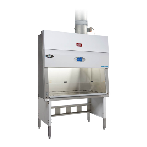
LabGard® ES Energy Saver Class II,
Type B2 Laminar Flow
Biosafety Cabinet
Models
NU-560-400/600
Bench/Console
Operation & Maintenance Manual
(Series C)
Revision 2
September 2020
Manufactured By:
NuAire, Inc.
2100 Fernbrook Lane
Plymouth, MN 55447
Toll-Free: 1-800-328-3352
In Minnesota: (763)-553-1270
Fax: (763)-553-0459
Page 1 of 103
Advertisement
Table of Contents

Related Manuals for NuAire LabGard NU-560-600


Summarization of Contents
1.0 General Information
1.1 Description
Provides a detailed description of the LABGARD® ES Model NU-560 Biosafety Cabinet.
1.2 Safety Instructions
Details safety features and important procedures for operating the LFBSC.
1.3 Explanation of Symbols
Defines symbols used in the manual for hazard identification and important notes.
4.0 Shipments
4.1 Damaged Shipments
Details steps for reporting and inspecting visible and concealed shipment damage.
5.0 Installation Instructions
5.1 Location
Discusses ideal placement of the biosafety cabinet within the laboratory environment.
5.2 Set-Up Instructions
Provides step-by-step guidance for cabinet assembly and initial setup procedures.
5.2.7 Exhaust/Supply Duct Installation Guidelines
Provides guidelines for installing exhaust and supply ductwork for the cabinet.
5.2.8 Final Assembly
Details the final steps for assembling the cabinet after installation.
5.3 Exhaust/Supply Air Checks
Describes checks for proper exhaust and supply airflow performance.
5.4 Certification Testing Methods and Equipment
Outlines recommended tests and equipment for cabinet certification and commissioning.
6.0 Operating the NU-560
6.1 Biosafety Cabinet Control
Explains the Biosafety Cabinet Control (BSCC) system and its operational capabilities.
6.1.1 Overview
Provides an overview of the BSCC system's design and functions.
6.1.2 Standby Mode
Describes the cabinet's display and functions when in standby mode.
6.1.3 Run Mode
Details the cabinet's operation during the run mode, including warm-up and aseptic cleaning.
6.1.4 Standby/Run Mode Alarms
Explains different alarm types and indicators for standby and run modes.
6.1.5 Menu Icon
Describes the function of the menu icon and its associated menu items.
6.1.5.1 Setpoint / Limits
Details how to view and manage airflow control setpoints and alarm limits.
6.1.5.2 Timer Settings
Explains the configuration of various timer functions for cabinet operation.
6.1.5.3 Historical Performance
Describes how to access and view historical data for downflow and inflow performance.
6.1.5.4 Calibration/Service
Covers accessing the password-protected area for cabinet calibration and service.
6.1.5.5 Display Setting
Explains how to adjust display features like background color and brightness.
6.1.5.6 Change User Password
Details the procedure for changing the user password for system access.
6.1.5.7 System Information
Displays cabinet model, serial number, and software revision information.
6.1.6 Night Setback (Optional)
Explains the optional night setback feature for energy savings during non-usage periods.
6.1.7 Remote Override (Optional)
Describes the optional remote override feature for controlling cabinet operation remotely.
6.2 Operating Guidelines
6.2.1 Know Your "Safe Working Area"
Defines the safe work area within the cabinet and proper material placement.
6.2.2 Minimize Penetration of "Air Curtain"
Advises on minimizing hand and arm movements through the air curtain.
6.2.3 Minimize Room Activity
Discusses the importance of minimizing room activity to avoid disrupting airflow.
6.2.4 Utilize Unidirectional Airflow
Explains how to maintain unidirectional airflow for effective containment.
6.2.5 Employ Aseptic Technique
Stresses the importance of aseptic techniques for optimal cabinet performance.
6.3 Operating Sequence
6.3.1 Start Up
Details the initial steps for starting up the biosafety cabinet.
6.3.2 Wipe down
Describes the disinfection procedure for the cabinet's interior surfaces.
6.3.3 Materials & Equipment
Provides guidance on placing materials and equipment inside the cabinet.
6.3.4 Air Purge
Explains the air purge step to remove loose contamination.
6.3.5 Perform Work
Covers the execution of work procedures within the cabinet, including safety.
6.3.6 Terminal Purging & Wipe down
Describes the final purging and decontamination steps after work completion.
6.3.7 Paper Catch/Prefilter
Instructions for checking and cleaning the paper catch/prefilter.
6.3.8 Shut Down
Details the procedure for safely shutting down the biosafety cabinet.
6.5 Cleaning Procedures
6.5.1 General
Offers general advice and best practices for cleaning laboratory equipment.
6.6 Hazardous Drug Decontamination Procedures
6.6.1 Preparation
Outlines necessary personal protective equipment and preparation steps.
6.6.2 Procedure
Describes the step-by-step process for decontaminating the cabinet.
6.6.3 Assembly
Covers reassembly steps after decontamination is complete.
7.0 General Maintenance
7.1 Decontamination
Explains the process and precautions for decontaminating the cabinet for maintenance.
7.2 LED Lamp Replacement
Details the procedure for replacing the cabinet's LED lamps.
7.3 HEPA Filter/Motor Replacement
Covers the replacement process for HEPA filters and the motor/blower assembly.
7.3.1 Supply Filter Replacement
Guides on how to replace the supply HEPA filter.
7.3.2 Exhaust Filter Replacement
Guides on how to replace the exhaust HEPA filter.
7.3.3 Motor/Blower Assembly Removal
Details the removal of the motor/blower assembly for service or replacement.
7.4 Sliding Window Replacement and Manual Adjustment
Covers sliding window replacement and adjustment procedures.
7.5 Airflow Control System Setup and Calibration
Details the procedures for setting up and calibrating the airflow control system.
7.5.1 General
Provides an introduction to the setup and calibration requirements for the airflow system.
7.5.2 Calibration/Service Menu
Describes the menu options available for calibrating and servicing the system.
7.5.2.2 Setpoints/Limits
Explains how to verify and alter airflow setpoints and alarm limits.
7.5.3 Airflow Calibration
Guides the process of balancing and calibrating cabinet airflow using specific measurement methods.
7.5.3.2 Exhaust Volume Calibration with the NU-951-012 Motorized Butterfly Valve
Details calibrating exhaust volume using a motorized butterfly valve.
7.5.3.3 Downflow Calibration
Explains the procedure for calibrating the downflow airflow sensor.
7.5.3.4 Night Setback Calibration (Optional)
Describes how to calibrate the night setback feature for energy savings.
7.6 HEPA Filter Leak Test
Details the procedure for testing HEPA filter and seal integrity.
7.7 Airflow Smoke Pattern Test
Describes how to perform a smoke pattern test to evaluate airflow performance.
7.8 Site Installation Assessment Tests
Covers tests to verify airflow or pressure setpoints trigger alarms.
7.8.1 Sash Alarm
Details the test procedure for verifying the sash alarm function.
7.8.2 Airflow or Pressure Alarm
Explains how to test airflow/pressure alarms by reducing airflow.
7.10 Main Control Board Description & Replacement
7.10.1 Main Control Board Replacement
Details the steps for removing and installing the main control board.
7.10.2 Main Control Board Fuse Replacement
Explains how to replace fuses on the main control board.
7.10.4 Cabinet Reset
Describes the software reset options for the main control board.
7.11 Digital Airflow Sensor Description & Replacement
7.11.1 Downflow Velocity Sensor
Details the downflow velocity sensor, its function, and replacement.
7.11.2 Exhaust Pressure Sensor
Details the exhaust pressure sensor, its function, and replacement.
8.0 Error Messages, Troubleshooting, Option-Diagnostics & Airflow Sensor Performance Verification
8.1 Error Message Troubleshooting Guide
A guide linking error messages to their indicators and corrective actions.
8.2 Calibration/Service Menu
8.2.1 General
Provides general access guidelines for the calibration and service menu.
8.2.2 Calibration/Service Menu
Lists the sub-menu items available within the calibration/service menu.
8.2.2.1 Blower/Damper Setup
Details options for configuring the blower and damper settings.
Exhaust Damper Set up
Covers the setup and configuration of the exhaust damper.
Exhaust Override
Explains the exhaust override parameter and its safety implications.
8.2.2.2 Service
Describes accessing service options for configuration and calibration.
Run Times
Allows viewing, altering, or resetting UV light and blower motor run timers.
Certification Date
Enables viewing and updating the cabinet's certification date and setting reminders.
8.2.2.3 Option Setup
Allows configuration of various optional parameters for the cabinet.
Alarm Setup
Details the configuration of alarm silence time and downflow alarm delay.
Interlock Features
Explains how to enable or disable various interlock features.
Auxiliary Features
Provides access to AUX relay functions and accessory outlet controls.
8.2.2.4 Diagnostics
Allows technicians to exercise and test control system functions.
8.3 Airflow Sensor Performance Verification
8.3.1 Run Mode
Describes how to check airflow sensor performance during normal operation.
9.0 Remote Contacts
9.1 Fan Relay
Details the fan relay contacts and their activation when the blower is on.
9.2 Alarm Relay
Describes the alarm relay contacts activated by airflow alarm conditions.
9.3 AUX Relay
Explains the AUX relay contacts and their conditional logic.
9.4 Remote Override
Covers the remote override contacts for shutting down the cabinet.
9.5 Night Setback
Describes the night setback contacts for placing the cabinet in setback mode.
10.0 Optional Equipment
10.1 Ultraviolet Light
Details the operation, precautions, and maintenance of the ultraviolet light feature.
11.0 Electrical/Environmental Requirements
11.1 Electrical
Specifies the electrical requirements, including voltage, frequency, and amperage.
11.2 Operational Performance
Defines the operational parameters for temperature, humidity, and altitude.
11.3 Light Exposure
Specifies the standard fluorescent lighting intensity.
11.4 Installation Category
Defines the installation category related to transient over voltage.
11.5 Pollution Degree
Describes the pollution degree of the operating environment.
11.6 Chemical Exposure
Advises on chemical exposure limitations and decontamination methods.
11.7 EMC Performance
Details EMC performance classifications for light industrial environments.
Need help?
Do you have a question about the LabGard NU-560-600 and is the answer not in the manual?
Questions and answers