Table of Contents
Advertisement
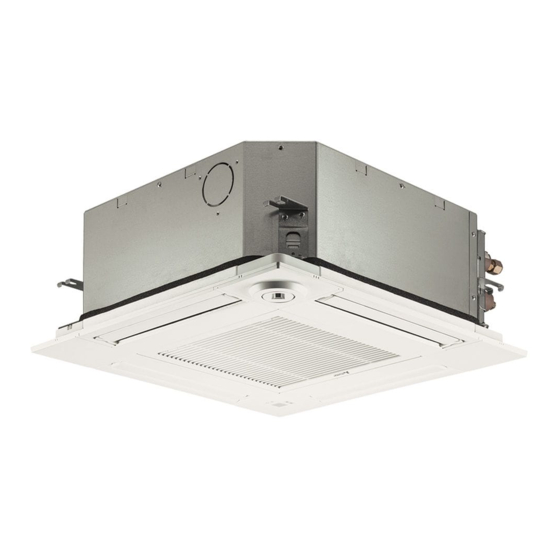
SPLIT-TYPE, HEAT PUMP AIR CONDITIONERS
TECHNICAL & SERVICE MANUAL
Indoor unit
[Model Name]
SLZ-M15FA2.TH
SLZ-M15FA2-ER.TH
SLZ-M15FA2-ET.TH
SLZ-M25FA2.TH
SLZ-M25FA2-ER.TH
SLZ-M25FA2-ET.TH
SLZ-M35FA2.TH
SLZ-M35FA2-ER.TH
SLZ-M35FA2-ET.TH
SLZ-M50FA2.TH
SLZ-M50FA2-ER.TH
SLZ-M50FA2-ET.TH
SLZ-M60FA2.TH
SLZ-M60FA2-ER.TH
SLZ-M60FA2-ET.TH
Model name
indication
TCH067.indd 1
TCH067.indd 1
[Service Ref.]
SLZ-M15FA2.TH
SLZ-M15FA2-ER.TH
SLZ-M15FA2-ET.TH
SLZ-M25FA2.TH
SLZ-M25FA2-ER.TH
SLZ-M25FA2-ET.TH
SLZ-M35FA2.TH
SLZ-M35FA2-ER.TH
SLZ-M35FA2-ET.TH
SLZ-M50FA2.TH
SLZ-M50FA2-ER.TH
SLZ-M50FA2-ET.TH
SLZ-M60FA2.TH
SLZ-M60FA2-ER.TH
SLZ-M60FA2-ET.TH
INDOOR UNIT
R32/R410A
CONTENTS
1. REFERENCE MANUAL ...................... 2
2. SAFETY PRECATION ......................... 2
3. PARTS NAMES AND FUNCTIONS ..... 9
4. SPECIFICATIONS ............................. 10
5. NOISE CRITERION CURVES ........... 10
6. OUTLINES AND DIMENSIONS ......... 12
7. WIRING DIAGRAM ............................ 14
8. REFRIGERANT SYSTEM DIAGRAM ..... 15
9. TROUBLESHOOTING ....................... 16
10. 4-WAY AIRFLOW SYSTEM ............... 29
11. DISASSEMBLY PROCEDURE .......... 31
PARTS CATALOG (TCB067)
September 2021
No. TCH067
29/9/2564 13:36:28
29/9/2564 13:36:28
Advertisement
Table of Contents

Related Manuals for Mitsubishi Electric TH


Summarization of Contents
REFERENCE MANUAL
OUTDOOR UNIT'S SERVICE MANUAL
Lists service manuals for various outdoor units.
SAFETY PRECAUTIONS
MEANINGS OF SYMBOLS DISPLAYED ON THE UNIT
Explains warning symbols used on the unit.
ALWAYS OBSERVE FOR SAFETY
General safety rule before accessing terminals: disconnect power.
CAUTIONS RELATED TO NEW REFRIGERANT
Repair Preparation and Precautions
Steps and safety measures before and during repair service.
Piping, Oil, and Charging Guidelines
Rules for using new pipes, cleaning, storage, oil type, and refrigerant charging.
Refrigerant Handling Tools and Procedures
Lists essential tools and proper methods for handling R32/R410A refrigerant.
Specified Refrigerant and Ventilation Safety
Using only specified refrigerant and ventilating room during leaks.
SERVICE SAFETY WARNINGS
General Service Prohibitions
Do not alter unit, use authorized personnel, keep ignition sources away.
Installation and Repair Precautions
Follow manual, use specified parts, ventilate for brazing.
Post-Service Procedures
Recover refrigerant completely, do not release, charge properly, install filter drier.
R32 REFRIGERANT SERVICE GUIDELINES
Servicing Area Safety Checks
Checks on area, work procedure, fire extinguisher, ignition sources, ventilation.
Equipment and Electrical Component Safety
Checks on refrigeration equipment, electrical devices, and casing integrity during repairs.
R32 REFRIGERANT OPERATIONAL PROCEDURES
Component Repair, Cabling, and Leak Detection
Repairing safe components, checking cabling, and leak detection methods.
Refrigerant Handling and Decommissioning
Procedures for refrigerant removal, charging, decommissioning, and labelling.
REFRIGERANT RECOVERY AND HANDLING
Safe Refrigerant Recovery Process
Detailed steps for safe refrigerant recovery, cylinder handling, and transfer.
ESSENTIAL SERVICE TOOLS
R32/R410A Refrigerant Tools List
Lists and specifications for essential tools for R32/R410A refrigerant.
INDOOR UNIT COMPONENTS AND FUNCTIONS
Indoor Unit Part Identification
Diagram and labels for indoor unit components like filter, vanes, and intake.
UNIT SPECIFICATIONS AND NOISE DATA
Indoor Unit Technical Specifications
Technical data for indoor units, including electrical and dimensional specs.
Noise Criterion Curves by Frequency
Graphs showing sound pressure levels at various frequencies for different models.
NOISE CURVES FOR SPECIFIC MODELS
SLZ-M35/50/60FA2 Series Noise Curves
Noise criterion curves for SLZ-M35, M50, and M60FA2 models.
Sound Level Measurement Notes
Notes on how sound levels are measured and potential variations.
OUTLINES AND DIMENSIONS
Unit Dimensions and Pipe Sizes
Provides physical dimensions and refrigerant pipe sizes for different models.
REMOTE CONTROLLER DIMENSIONS
Wireless and Wired Controller Dimensions
Provides dimensions for wireless and wired remote controllers.
WIRING DIAGRAM AND SYMBOLS
Indoor Unit Electrical Wiring Diagram
Schematic showing electrical connections within the indoor unit.
Wiring Legend and Important Notes
Explanation of symbols, codes, and important notes for wiring.
REFRIGERANT SYSTEM DIAGRAM
Refrigerant Flow and Components
Diagram illustrating refrigerant path and key components like thermistors and strainers.
TROUBLESHOOTING AND DIAGNOSIS METHODS
Self-Diagnosis Summary and Remote Controller Diagnosis
Summary of check codes and procedures for diagnosing issues via remote controller.
SELF-DIAGNOSIS ERROR CODE TABLES
Indoor Unit Error Codes (P-Series)
Lists error codes (P-series) and their corresponding symptoms for indoor units.
Other Unit Error Codes (U, E, etc.)
Lists error codes (U, E, etc.) and symptoms for units other than indoor.
SELF-DIAGNOSIS ACTION TABLE (PART 1)
Troubleshooting Codes P1, P2, P4, P5
Detailed troubleshooting steps for specific error codes related to thermistors and drain system.
SELF-DIAGNOSIS ACTION TABLE (PART 2)
Troubleshooting Codes P6 and P8
Detailed troubleshooting for freezing/overheating protection and pipe temperature issues.
SELF-DIAGNOSIS ACTION TABLE (PART 3)
Troubleshooting Codes P9, PL, E0/E4
Troubleshooting for thermistor, refrigerant circuit, and remote controller signal errors.
SELF-DIAGNOSIS ACTION TABLE (PART 4)
Troubleshooting Codes E3/E5, E6, E7, FB(Fb), E1/E2
Troubleshooting for remote controller, communication, and board errors.
SELF-DIAGNOSIS ACTION TABLE (PART 5)
Troubleshooting Codes PA and PB
Detailed troubleshooting for water leakage abnormalities and fan motor issues.
SYSTEM PROBLEM TROUBLESHOOTING
Indoor Controller Board LED Status Issues
Troubleshooting when LED2 on the indoor controller board is off or blinking.
INDOOR CONTROLLER BOARD TEST POINTS
Test Point Diagram and Connector Locations
Diagram showing test points and connector locations on the indoor controller board.
DIP SWITCH AND JUMPER WIRE FUNCTIONS
Capacity Setting (SW2)
Explains how to set capacity using DIP switch SW2.
Wireless Remote Pair Number Setting (J41/J42)
Details on setting the pair number for wireless remote controllers using jumper wires.
MAIN COMPONENT TROUBLESHOOTING CRITERIA
Sensor and Motor Resistance Checks
Methods to check resistance of thermistors, vane motor, and i-see sensor motor.
Drain System Component Checks
Procedures for checking the drain pump and float switch.
i-see Sensor Connection Check
Procedure to detect the connection of the i-see Sensor.
THERMISTOR CHARACTERISTICS AND FAN MOTOR CHECK
Thermistor Resistance vs. Temperature Graph
Graph illustrating the relationship between thermistor resistance and temperature.
DC Fan Motor and Controller Board Diagnostics
Procedure for diagnosing issues with the DC fan motor and indoor controller board.
AIRFLOW SYSTEM OPERATIONS
Fresh Air Intake Installation and Characteristics
Guidance on fresh air intake duct installation and airflow/pressure characteristics.
Operation with Duct Fan (Booster Fan)
Instructions for operating the indoor unit in conjunction with a duct fan.
HORIZONTAL VANE ADJUSTMENT PROCEDURE
Fixing Horizontal Vane Steps
Steps for adjusting and fixing the horizontal vane position.
UNIT DISASSEMBLY PROCEDURES (PART 1)
Removing Air Intake Grille, Filter, and Panel Components
Steps for removing the air intake grille, filter, connector box, corner panel, and main panel.
UNIT DISASSEMBLY PROCEDURES (PART 2)
Removing Electrical Parts and Room Thermistor
Steps for removing electrical components and the room temperature thermistor (TH1).
Removing the Drain Pan
Steps for removing the drain pan from the unit.
UNIT DISASSEMBLY PROCEDURES (PART 3)
Removing Pipe Thermistors and Fan Motor
Steps for removing pipe thermistors (TH2/TH5) and the fan motor (MF).
UNIT DISASSEMBLY PROCEDURES (PART 4)
Removing Drain Pump, Float Switch, and Heat Exchanger
Steps for removing the drain pump, float switch, and heat exchanger.
REMOTE CONTROLLER FUNCTIONS (PAR-41MAA)
Controller Interface and Basic Button Functions
Diagram of the controller interface and explanation of basic buttons like ON/OFF, SELECT, RETURN, MENU.
Function Buttons F1-F4 Operation
Explanation of the functions of buttons F1, F2, F3, and F4 on the remote.
Display Indicators and Backlit LCD
Explanation of the ON/OFF lamp and the backlit LCD.
REMOTE CONTROLLER DISPLAY MODES AND ICONS
Display Modes (Full/Basic) and Icons Explained
Explanation of display modes, icons for operation, timers, settings, and indicators.
REMOTE CONTROLLER MENU STRUCTURE OVERVIEW
Main Menu Navigation Hierarchy
Overview of the main menu hierarchy for operations, timers, settings, maintenance, and service.
Maintenance and Service Menu Sections
Sections for accessing maintenance tasks and service functions.
DETAILED MENU OPTIONS (MAINTENANCE & SERVICE)
Maintenance Menu Options Explained
Details on Error Information, Filter Information, Cleaning, and Panel operations.
Service Menu Options Explained
Details on Test Run, Maintenance Info, Settings, Check, and Others.
MAIN MENU SETTINGS AND DETAILS
Operation, High Power, and Comfort Settings
Details on setting Vane, 3D i-See, Vent, High Power, and Comfort modes.
Timer and Energy Saving Configuration
Configuration for Timers (ON/OFF, Auto-OFF, Weekly) and Energy Saving features.
Energy Saving Schedules and Data Viewing
Setting energy saving schedules and viewing consumption data.
MAIN MENU STRUCTURE AND FUNCTION SETTINGS
Initial Setup and Display Settings
Initial setup options including basic settings, display adjustments, and language selection.
Maintenance and Service Menu Functions
Details on Error Info, Filter Info, Cleaning, Test Run, Input Info, Settings, Check, and Others.
REMOTE CONTROLLER FUNCTIONS (PAR-SL97A-E)
PAR-SL97A-E Controller Interface and Buttons
Diagram and explanation of buttons on the PAR-SL97A-E remote controller.
REMOTE CONTROLLER DISPLAY (PAR-SL101A-E)
PAR-SL101A-E Display Modes and Icons
Explanation of display modes, icons for operation, settings, and indicators.
REMOTE CONTROLLER ERROR INFORMATION
Viewing and Resetting Error Codes
Procedure for checking and resetting error information displayed on the remote controller.
CHECKING ERROR INFORMATION VIA MAINTENANCE MENU
Accessing Error Information Screen
How to view error information from the Maintenance menu when no errors are active.
SERVICE MENU ACCESS AND PASSWORD MANAGEMENT
Entering and Resetting the Maintenance Password
Steps to access the Service menu, including password entry and reset.
Navigating Service Menu Screens
Instructions on how to move between screens within the Service menu.
REMOTE CONTROLLER TEST RUN OPERATIONS
PAR-41MAA Test Run and Auto Vane Check
Steps for performing test runs and auto vane checks using the PAR-41MAA remote.
REMOTE CONTROLLER TEST RUN PROCEDURES (OTHER MODELS)
PAR-SL97A-E Test Run Procedure
Procedure for performing a test run using the PAR-SL97A-E remote controller.
PAR-SL101A-E Test Run Procedure
Procedure for performing a test run using the PAR-SL101A-E remote controller.
REMOTE CONTROLLER FUNCTION SETTINGS (PAR-41MAA)
Accessing and Setting Unit Functions
Steps to access and set functions like mode, refrigerant address, and unit number.
Function Setting Patterns and Notes
Explanation of display formats, setting patterns, and important notes for function settings.
REMOTE CONTROLLER FUNCTION SETTINGS (PATTERNS)
Function Setting Pattern 2 and Notes
Details on the second pattern for function settings and related notes.
REMOTE CONTROLLER FUNCTION SETTINGS (PAR-SL97A-E)
Function Selection Procedure Flowchart and Instructions
Flowchart and step-by-step guide for selecting functions using the wireless remote.
REMOTE CONTROLLER FUNCTION SETTINGS (PAR-SL101A-E)
Function Selection Procedure Steps
Step-by-step guide for selecting functions using the PAR-SL101A-E remote controller.
ROTATION SETTING PROCEDURE (WIRED REMOTE)
Setting Rotation and Support Functions
Instructions for setting rotation period, backup options, and support functions.
Updating and Resetting Rotation Settings
Procedures for updating and resetting rotation settings, including reset method.
ERROR HISTORY MANAGEMENT FUNCTIONS
Viewing and Deleting Unit Error History
Steps to view, manage, and delete the unit's error history records.
PRELIMINARY ERROR HISTORY MANAGEMENT
Viewing and Deleting Preliminary Error Records
Procedure for viewing and deleting preliminary error history records.
SELF-DIAGNOSIS OPERATIONS AND ERROR RESET
PAR-41MAA Self-Diagnosis and Error Reset
Procedure for performing self-diagnosis and resetting errors using the PAR-41MAA remote.
MALFUNCTION DIAGNOSIS PROCEDURES FOR REMOTE CONTROLLERS
PAR-SL97A-E Malfunction Diagnosis Steps
Procedure for diagnosing malfunctions using the PAR-SL97A-E remote controller.
PAR-SL101A-E Malfunction Diagnosis Steps
Procedure for diagnosing malfunctions using the PAR-SL101A-E remote controller.
REMOTE CONTROLLER DIAGNOSIS AND CHECKING
Performing Remote Controller Check and Interpreting Results
Steps to diagnose and check the remote controller's functionality and interpret results.
SMOOTH MAINTENANCE PROCEDURES
Setting and Viewing Smooth Maintenance Data
Procedure for setting smooth maintenance parameters and viewing operation data.
REQUEST CODE FOR OPERATION DATA RETRIEVAL
Setting Refrigerant Address and Request Code
Procedure for setting refrigerant address and requesting operation data.
Need help?
Do you have a question about the TH and is the answer not in the manual?
Questions and answers