Table of Contents
Advertisement
Quick Links
SERVICE MANUAL
Ver. 1.1 2012.07
• HCD-GPX5G is the amplifi er, USB, CD player and tuner
section in MHC-GPX5.
• HCD-GPX7G is the amplifi er, USB, CD player and tuner
section in MHC-GPX7.
• HCD-GPX8G is the amplifi er, USB, CD player and tuner
section in MHC-GPX8.
"WALKMAN" and "WALKMAN" logo are registered
trademarks of Sony Corporation.
MPEG Layer-3 audio coding technology and patents licensed
from Fraunhofer IIS and Thomson.
Windows Media is either a registered trademark or trademark
of Microsoft Corporation in the United States and/or other
countries.
This product contains technology subject to certain
intellectual property rights of Microsoft.
Use or distribution of this technology outside of this product
is prohibited without the appropriate license(s) from
Microsoft.
Amplifi er section
The following are measured at Mexican model:
AC 120 V – 240 V, 60 Hz
Other models:
AC 120 V – 240 V, 50/60 Hz
MHC-GPX8
Front/Satellite speaker
Power Output (rated):
300 W + 300 W (at 4 ohms, 1 kHz,
1% THD)
Front speaker
RMS output power (reference):
360 W + 360 W (per channel at 6 ohms,
1 kHz)
Satellite speaker
RMS output power (reference):
180 W+ 180 W (per channel at 12 ohms,
1 kHz)
Subwoofer
RMS output power (reference):
260 W + 260 W (per channel at 8 ohms,
100 Hz)
MHC-GPX7
HIGH speakers
Power Output (rated):
300 W + 300 W (at 4 ohms, 1 kHz,
1% THD)
RMS output power (reference):
495 W + 495 W (per channel at 4 ohms,
1 kHz)
LOW speakers
RMS output power (reference):
180 W + 180 W (10 ohms, 100 Hz)
9-890-600-02
Sony Corporation
2012G08-1
©
2012.07
Published by Sony EMCS (Malaysia) PG Tec
HCD-GPX5G/GPX7G/GPX8G
All manuals and user guides at all-guides.com
Model Name Using Similar Mechanism
CD Section
CD Mechanism Type
Optical Pick-up Name
SPECIFICATIONS
MHC-GPX5
Front speaker
Power Output (rated):
240 W + 240 W (at 5 ohms, 1 kHz,
1% THD)
RMS output power (reference):
370 W + 370 W (per channel at 5 ohms,
1 kHz)
Subwoofer
RMS output power (reference):
360 W (5 ohms, 100 Hz)
Inputs
TV (AUDIO IN) L/R
Voltage 1.2 V, impedance 47 kilohms
DVD/SAT (AUDIO IN) L/R
Voltage 1.2 V, impedance 47 kilohms
PC/GAME (AUDIO IN) L/R
Voltage 1.2 V, impedance 47 kilohms
MIC (MHC-GPX8/MHC-GPX7 only)
Sensitivity 1 mV, impedance
10 kilohms
A (USB),
B (USB) port: Type A
USB section
Supported bit rate
MP3 (MPEG 1 Audio Layer-3):
32 kbps – 320 kbps, VBR
WMA: 48 kbps – 192 kbps
AAC: 48 kbps – 320 kbps
Sampling frequencies
MP3 (MPEG 1 Audio Layer-3):
32 kHz/44.1 kHz/48 kHz
WMA: 44.1 kHz
AAC: 44.1 kHz
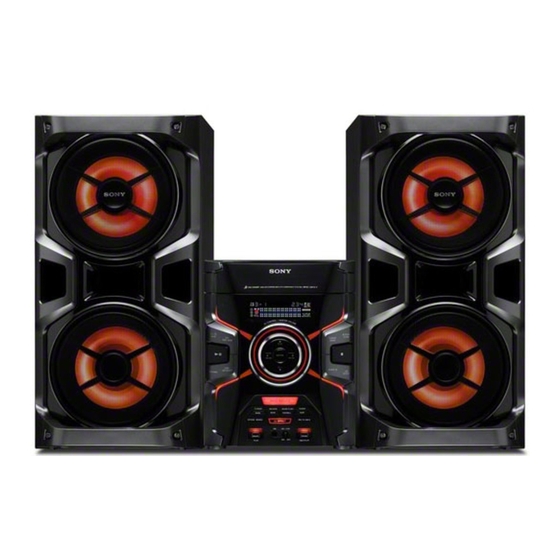
Photo: HCD-GPX8G (E2 Model)
Supported USB device
Mass Storage Class
Maximum current
500 mA
Disc player section
System
Compact disc and digital audio system
Laser Diode Properties
Emission Duration: Continuous
Laser Output*: Less than 44.6 μW
* This output is the value measurement
at a distance of 200 mm from the
objective lens surface on the Optical
Pick-up Block with 7 mm aperture.
Frequency response
20 Hz – 20 kHz
Signal-to-noise ratio
More than 90 dB
Dynamic range
More than 88 dB
Tuner section
FM stereo, FM/AM superheterodyne tuner
Antenna:
FM lead antenna
AM loop antenna
FM tuner section
Tuning range
87.5 MHz – 108.0 MHz (50 kHz step)
AM tuner section
Tuning range
Pan American models:
530 kHz – 1,710 kHz (10 kHz step)
531 kHz – 1,710 kHz (9 kHz step)
COMPACT DISC RECEIVER
E Model
NEW
CDM74I-DVBU201//M
CMS-ST6RFS3
Other models:
530 kHz – 1,610 kHz (10 kHz step)
531 kHz – 1,602 kHz (9 kHz step)
General
Power requirements
Mexican model: AC 120 V – 240 V, 60 Hz
Other models: AC 120 V – 240 V, 50/60 Hz
Power consumption
MHC-GPX8: 250 W
MHC-GPX7: 230 W
MHC-GPX5: 200 W
Dimensions (w/h/d) (excl. speakers)
(Approx.)
280 mm × 355 mm × 440 mm
Mass (excl. speakers) (Approx.)
HCD-GPX8G/HCD-GPX7G/
HCD-GPX5G: 7.0 kg
Supplied accessories
Remote control (1)
R6 (Size AA) batteries (2)
FM lead/AM loop antenna (1)
Spacer A (MHC-GPX8 only) (2)
Spacer B (MHC-GPX8 only) (2)
Speaker pads (MHC-GPX7 only) (8)
Design and specifi cations are subject to change
without notice.
Advertisement
Table of Contents

Related Manuals for Sony HCD-GPX8G E2


Summarization of Contents
HCD-GPX5G/GPX7G/GPX8G Service Manual
Specifications
Detailed technical specifications for the HCD-GPX series hi-fi system.
Servicing Notes
Chip Component Replacement Precautions
Guidelines for safely replacing chip components, including capacitor handling.
Leakage Test Procedures
Procedures for testing AC leakage current to ensure user safety.
Servicing Notes
Optical Pick-up and Laser Diode Handling
Precautions for handling the optical pick-up, laser diode, and flexible board.
Solder and Tray Lock Procedures
Guidelines for unleaded solder use and releasing the disc tray lock.
Disassembly Procedures
Disassembly Flowchart
A flowchart detailing the sequence of disassembly steps for the unit.
Test Modes
Panel Test Mode
Mode for testing fluorescent indicator tube, LEDs, keys, and software versions.
Common Test Mode
Mode for checking amplifier section operations like GEQ and volume control.
User and Cold Reset Procedures
Procedures to reset user data and system to initial conditions.
Tuner Step and CD Ship Mode
Method to toggle AM tuning step and enter CD ship mode with memory clear.
Special Test Modes
CD Ship Mode (No Memory Clear)
Mode to move optical pick-up for vibration durability after repair.
CD Tray Lock and Factory Preset
Modes to lock the disc tray and load factory preset frequencies.
CDM Aging, History, and Protect Modes
Modes for checking aging data, history logs, and protect status.
Amplifier Circuit Troubleshooting
Power Supply Circuit Troubleshooting
Potential causes for power supply circuit defects when PROTECT mode is active.
Electrical Checks
CD Section Electrical Checks
Notes on CD block construction and checks, including focus bias.
Tuner Section FM Auto Stop Check
Procedure for checking FM auto-stop using a signal generator.
Diagrams
CD/USB Section Block Diagram
Block diagram illustrating the signal flow for the CD and USB playback sections.
Tuner1AM3R Board PWB
Tuner1AM3R Board Schematic
Schematic diagram for the Tuner1AM3R board, showing IC connections.
Exploded Views
Case Section Exploded View
Exploded view and parts list for the main case components.
Electrical Parts List
4CH DAMP Parts List
List of electrical components for the 4CH DAMP board, including capacitors.
Servicing Notes
Switching Regulator Troubleshooting Flowchart
Flowchart for diagnosing switching regulator issues and power voltage checks.
Need help?
Do you have a question about the HCD-GPX8G E2 and is the answer not in the manual?
Questions and answers