Advertisement
Table of Contents
- 1 Front Panel Descriptions
- 2 Back Panel Descriptions
- 3 Technical Parameters
- 4 Installation
- 5 Constant Voltage / Constant Current Characteristics
- 6 Operating Procedures
- 7 Constant Current Operation
- 8 Battery Charging Operation
- 9 Troubleshooting and Maintenance
- 10 Fuse Replacement
- Download this manual
Advertisement
Table of Contents

Related Manuals for VOLTEQ HY3050EX


Summary of Contents for VOLTEQ HY3050EX
- Page 1 REGULATED DC POWER SUPPLY USER MANUAL SINGLE OUTPUT SWITCH MODE DC POWER SUPPLY...
- Page 2 Please read this manual carefully before operating the power supply. 1. Introduction Volteq HY series single output switch mode DC power supplies are regulated variable DC power supplies designed to provide the most often required DC outputs in scientific and research institutions, schools and colleges, industrial R&D, as well as manufacturing and testing.
- Page 3 Temperature: -10°C to 40°C Relative humidity: <80% Table 2-1 Model Max. Voltage Max. Current Fuse Type and Input AC Weight (lbs) Rating 50/60Hz HY1550EX 15A/250V 110V/220V HY15150EX 150A air switch 110V or 220V HY3050EX air switch 110V/220V HY3080EX air switch...
-
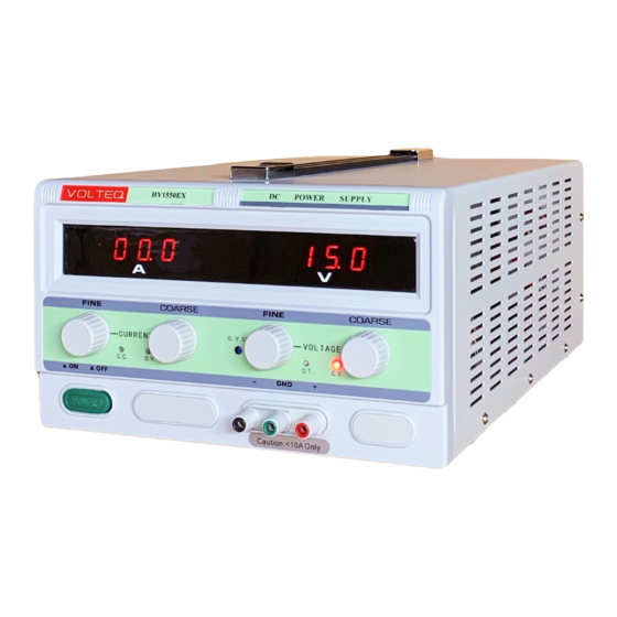
Page 4: Front Panel Descriptions
2-2 Front Panel Descriptions (1) Trademark and Model #: shows Volteq as trademark and the actual model number of the power supply. (2) Digital ammeter: displays the actual output always; this equates to the set value if in CC mode. - Page 5 (9) CC indicator light: this indicator turns red when the power supply is in constant current (CC) mode (See 3-2). (10) OV indicator: this indicator turns red when the power supply is over-voltage protected. The power supply will not respond to user control until it's reset (See 4-2 for more details). (11) Over-temperature (OT) indicator: this indicator turns red when the internal temperature of the power supply is too high, and the power supply output is disabled.
-
Page 6: Back Panel Descriptions
2-3 Back Panel Descriptions (16) Positive Terminal. (17) Negative Terminal. (18) Ground Terminal: this is connected to the case. (19) Cooling fan: the fan is turned on briefly when the power supply is energized; afterwards it is turned on when internal temperature of the power supply rises above 45℃. -
Page 7: Technical Parameters
Warning: To avoid electrical shock, the power plug ground pin must be connected to AC ground. Warning: the voltage indicated on the power supply must match the AC voltage, otherwise the power supply will be damaged (plugging a power supply rated for 110V into 220V AC), or the maximum output would not be reached (plugging a 220V power supply into 110V AC). - Page 8 voltage of 110V±10%. Warning: The voltage indicated on the power supply (look for a sticker on the case close to the rear) must match the AC voltage, otherwise the power supply will be damaged (plugging a power supply rated for 110V into 220V AC;...
-
Page 9: Constant Voltage / Constant Current Characteristics
power supply on or off with a inductive load connected! 2) Installation: For better heat dissipation, the two sides and back of the power supply should have at least 10cm space from the walls. The cooling fan is controlled by thermistor and will turn on automatically when the temperature of the heat sink is above 45°C. - Page 10 For example, if the load resistance (R) is such that the current limit (set by knobs 4 and 5) is higher than the voltage limit (set by knobs 6 and 7) divided by R (i.e., voltage limit is lower than current limit for the load R connected), the power supply operates in the constant voltage (CV) mode.
-
Page 11: Operating Procedures
3-3 Operating Procedures a) With the power switched off, leave the OV limit (8) to maximum position (factory default) or adjust per instructions at 3-5. b) Make sure that the AC line voltage matches the input voltage of the power supply. c) Make sure there is no load connected, plug power cord into the AC outlet. -
Page 12: Constant Current Operation
2) Constant Current Operation e) Adjust current knobs (knobs 4 or 5) to slightly above zero so that CV indicator light is on, adjust voltage control (knobs 6 & 7) to set voltage to the desired voltage limit (this is the maximum voltage you want to operate at). - Page 13 position of the coarse current knob (knob 5). Otherwise, skip this step. f) Turn the coarse current knob to minimum position or slightly above zero while still keeping the CV light on. Use knobs 6 and 7 to set the voltage to desired charging voltage recommended by the battery manufacturer. g) Stop the output, then connect the battery while making sure that the polarity is correct (+ to + and –...
- Page 14 warranty. e) Adjust all 4 knobs (both current and voltage) to minimum position. f) Connect the external load to the output terminals. Make sure both "+" and "-" terminals are connected correctly. For output more than 10A, you must use the rear terminals. g) For CV operation, turn the current knobs to maximum position.
- Page 15 with a test lead with sufficient thickness. 3) Adjust the COARSE voltage knob (knob 7) slightly up so that the CC indicator turns red. 4) Adjust the CURRENT control (knobs 4 & 5) to reach the desired current level, repeat 3) if needed. 5) The current limit has now been preset.
-
Page 16: Troubleshooting And Maintenance
Warning: The following instructions are to be performed by knowledgeable personnel only. To avoid electrical shock, do not perform any servicing other than the contained in the operation instructions. For further questions, please contact factory support at support@volteq.com. 4-1 Fuse Replacement Some models are equipped with air switch, which is a reset-able breaker and does not require a fuse. - Page 17 on the rear panel where power cord is plugged into the device, as shown to the right: Warning: For continued fire protection, replace fuse only with fuse of the specified type and rating. All replacement fuses must be slow-blowing type. 4-2 Rest OV Protection When OV light is red, the power supply is in OV protected state, and will not respond to user input until the power supply is properly reset.
- Page 18 automatically. Typical cause of over-heating includes: 1) Not enough ventilation due to space limit. 2) Ambient temperature is too high. 3) The cooling fan stops working. 4) Output exceeds the rated range. Caution: the power supply can be operated at the maximum outputs (both current and voltage) for less than 15 minutes.
Need help?
Do you have a question about the HY3050EX and is the answer not in the manual?
Questions and answers