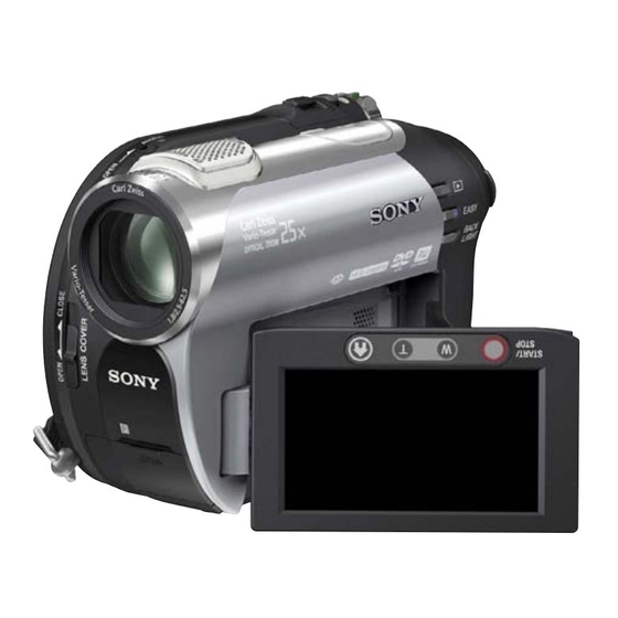
Sony Handycam DCR-DVD708 Service Manual
Hide thumbs
Also See for Handycam DCR-DVD708:
- Operating manual (139 pages) ,
- Operating manual (127 pages) ,
- Operating manual (136 pages)
Table of Contents
Advertisement
Quick Links
SERVICE MANUAL
Ver. 1.3 2007.07
Revision History
Revision History
How to use
How to use
Acrobat Reader
Acrobat Reader
Link
Link
SPECIFICATIONS
MODEL INFORMATION TABLE
SERVICE NOTE
The components identified by
mark 0 or dotted line with
mark 0 are critical for safety.
Replace only with part num-
ber specified.
DCR-DVD306E/DVD308/DVD308E/DVD708/DVD708E_L2
9-852-174-31
DCR-DVD306E/DVD308/DVD308E/
Photo: DCR-DVD308
DISASSEMBLY
BLOCK DIAGRAMS
FRAME SCHEMATIC DIAGRAM
Les composants identifiés par une
marque 0 sont critiques pour la
sécurité.
Ne les remplacer que par une pièce
portant le numéro spécifié.
Sony EMCS Co.
DVD708/DVD708E
DIGITAL VIDEO CAMERA RECORDER
RMT-835
LEVEL
US Model
Canadian Model
AEP Model
UK Model
East European Model
North European Model
E Model
Australian Model
Hong Kong Model
Chinese Model
Korea Model
Argentine Model
Brazilian Model
Japanese Model
SCHEMATIC DIAGRAMS
PRINTED WIRING BOARDS
REPAIR PARTS LIST
Published by Kohda TEC
2
2007G0500-1
© 2007.7
Advertisement
Table of Contents

Summarization of Contents
Service Note Procedures
Power Supply During Repairs
Procedures for maintaining power supply during repair operations.
Force Eject Disc Extraction
Method to manually eject a disc when the unit fails to eject.
Using Service Jig
Instructions for connecting and using the service jig tool.
Self-Diagnosis Function
Overview of the unit's self-diagnosis feature for error detection.
Self-Diagnosis Code Table
Detailed table mapping error codes to symptoms and corrections.
Disassembly Procedures
Overall Section Disassembly
Step-by-step guide for disassembling the main unit components.
Cabinet (L) Section Disassembly
Detailed disassembly instructions for the left side cabinet.
MD Block Disassembly
Procedure for disassembling the MD (Mechanism Deck) block.
Cabinet (R) Section Disassembly
Detailed disassembly instructions for the right side cabinet.
LCD Block Disassembly
Step-by-step guide for removing and disassembling the LCD unit.
Flexible Board Attachment Methods
Specific methods for attaching flexible boards during reassembly.
Cabinet Installation Precautions
Important precautions for installing cabinet parts during service.
Block Diagrams
Overall Block Diagram (1/5)
Comprehensive system block diagram, part 1 of 5.
Overall Block Diagram (2/5)
Comprehensive system block diagram, part 2 of 5.
Overall Block Diagram (3/5)
Comprehensive system block diagram, part 3 of 5.
Overall Block Diagram (4/5)
Comprehensive system block diagram, part 4 of 5.
Overall Block Diagram (5/5)
Comprehensive system block diagram, part 5 of 5.
Power Block Diagram (1/3)
Power supply system block diagram, part 1 of 3.
Power Block Diagram (2/3)
Power supply system block diagram, part 2 of 3.
Power Block Diagram (3/3)
Power supply system block diagram, part 3 of 3.
Diagrams and Wiring Boards
Frame Schematic Diagram
High-level overview schematic illustrating component interconnections.
Schematic Diagrams
Detailed circuit schematics for various unit sections.
Printed Wiring Boards
Layout diagrams showing component placement on PCBs.
Repair Parts List
Exploded Views
Illustrated diagrams showing part breakdowns for easy identification.
Electrical Parts List
Comprehensive list of electrical components with part numbers.


Need help?
Do you have a question about the Handycam DCR-DVD708 and is the answer not in the manual?
Questions and answers