Table of Contents
Advertisement
Quick Links
DIRECT-VENT FIREPLACE
OWNER'S OPERATION AND INSTALLATION MANUAL
BDV41N/P(A,B), AND DDV41N/P(A,B)
WARNING: If the information in this manual is not
followed exactly, a fire or explosion may result
causing property damage, personal injury, or loss
of life.
FOR YOUR SAFETY
Do not store or use gasoline or other flammable
vapors and liquids in the vicinity of this or any other
appliance.
FOR YOUR SAFETY
WHAT TO DO IF YOU SMELL GAS
• Do not try to light any appliance.
• Do not touch any electrical switch
• Do not use any phone in your building.
• Immediately call your gas supplier from a
neighbor's phone. Follow the gas supplier's
instructions.
• If you cannot reach your gas supplier, call the
fire department.
This appliance may be installed in an aftermarket* manufactured (mobile) home, where
not prohibited by local codes.
* Aftermarket: Completion of sale, not for purpose of resale, from the manufacturer.
BDV37N/P(A,B), DDV37N/P(A,B),
Save this manual for future reference.
®
WARNING: Improper installation,
adjustment, alteration, service, or
maintenance can cause injury or
property damage. Refer to this
manual for correct installation and
operational procedures. For as-
sistance or additional information
consult a qualified installer, ser-
vice agency, or the gas supplier.
— Installation and service must
be performed by a qualified in-
staller, service agency, or the gas
supplier.
— This appliance is only for use
with the type of gas indicated on the
rating plate. This appliance is not
convertible for use with other
gases, unless a certified kit is used.
Advertisement
Table of Contents

Related Manuals for Vanguard B)


Summary of Contents for Vanguard B)
- Page 1 DIRECT-VENT FIREPLACE OWNER’S OPERATION AND INSTALLATION MANUAL BDV37N/P(A,B), DDV37N/P(A,B), BDV41N/P(A,B), AND DDV41N/P(A,B) WARNING: If the information in this manual is not followed exactly, a fire or explosion may result causing property damage, personal injury, or loss of life. FOR YOUR SAFETY Do not store or use gasoline or other flammable vapors and liquids in the vicinity of this or any other appliance.
-
Page 2: Safety Information
DIRECT-VENT FIREPLACE (NATURAL/PROPANE/LP) SAFETY INFORMATION WARNINGS IMPORTANT: Read this owner’s manual carefully and completely before trying to assemble, oper- ate, or service this fireplace. Im- proper use of this fireplace can cause serious injury or death from burns, fire, explosions, electrical shock, and carbon monoxide poisoning. -
Page 3: Product Identification
PRODUCT IDENTIFICATION Top Louver Panel Nailing Flange Glass Door Assembly Blower Adjustment (Optional Installation) ON/OFF Switch Piezo Ignitor Valve Glowing Embers Lower Louver Panel Figure 1 - Vanguard Direct-Vent Fireplace BDV Series Top Louver Panel Nailing Flange Brass Trim Glass Door Assembly Brass Trim Blower... -
Page 4: Pre-Installation Preparation
DIRECT-VENT FIREPLACE (NATURAL/PROPANE/LP) PRE-INSTALLATION PREPARATION LOCATION AND SPACE REQUIREMENTS Determine the safest and most efficient loca- tion for your Vanguard direct-vent fireplace. Make sure that rafters and wall studs are not in the way of the venting system. Choose a location where the heat output is not affected by drafts, air conditioning ducts, windows or doors. -
Page 5: General Venting
PRE-INSTALLATION PREPARATION Continued 13" 29" " " 58" Note : Where two numbers are given the top number is exclusive to the 37" Fireplace and the bottom number is exclusive to the 41" Fireplace Figure 7 - Framing Clearances for Corner Installation Note: There must be a minimum clearance of 18"... - Page 6 DIRECT-VENT FIREPLACE (NATURAL/PROPANE/LP) GENERAL VENTING TERMINATION CAP A = clearance above grade, veranda, porch, deck, or balcony [*12 inches (305mm) minimum] B = clearance to window or door that may be opened [12 inches (305mm) minimum] C = clearance to permanently closed window [minimum 12 inches (305mm) recommended to prevent condensation on window] D = vertical clearance to ventilated soffit located above the terminal within a horizontal distance of 24 inches (610mm) from the...
-
Page 7: Venting Installation
• Unauthorized modification of the vent- ing system 105539 OWNER’S MANUAL • Installation of any component part not manufactured or approved by DESA International • Installation other than as instructed by these instructions WARNING: This gas fireplace and vent assembly must be vented directly to the outside. -
Page 8: Installation
DIRECT-VENT FIREPLACE (NATURAL/PROPANE/LP) VENTING INSTALLATION Continued INSTALLATION FOR HORIZONTAL TERMINATION 1. Determine the route your horizontal venting will take. Note: The location of the horizontal vent termination on the exterior wall must meet all local and national building codes and must not be easily blocked or obstructed. - Page 9 VENTING INSTALLATION Continued 3. Attach vent pipe assembly to the fire- place. Set fireplace in front of it’s perma- nent location to insure minimum clear- ances. Mark the wall for a 10" square hole (for noncombustible material such as masonry block or concrete, a 7 "...
- Page 10 DIRECT-VENT FIREPLACE (NATURAL/PROPANE/LP) VENTING INSTALLATION Continued Horizontal Termination Configurations Figures 17 through 21 show different con- figurations for venting with horizontal ter- mination. Each figure includes a chart with vertical minimum/maximum and horizon- tal maximum dimensions which must be met. Seal all connections with high tem- perature silicone sealant (outer pipe only) as specified in the second warning statement on page 7.
- Page 11 VENTING INSTALLATION Continued Venting with Two 90 Elbows Vertical (V) Horizontal (H 5' min. 2' max. 6' min. 4' max. 7' min. 6' max. 8' min. 8' min. 20' max. 8' max. Figure 20 - Horizontal Termination Configuration for Rigid Venting Using Two 90 Elbows Venting with Two 90 Elbows Vertical (V) Horizontal (H...
- Page 12 DIRECT-VENT FIREPLACE (NATURAL/PROPANE/LP) VENTING INSTALLATION Continued INSTALLATION FOR VERTI- CAL TERMINATION Determine the route your vertical vent- ing will take. If ceiling joists, roof rafters, or other framing will obstruct the venting system, consider an offset (see Figure 22) to avoid cutting loadbearing members.
- Page 13 VENTING INSTALLATION Continued 3. Lower the support box through the hole in the roof until the bottom of the box extends at least 2" below the ceiling (see Figure 24). Align the support box vertically and horizontally using a level. Temporarily tack the support box in place through the inside walls and into the roof sheathing.
- Page 14 DIRECT-VENT FIREPLACE (NATURAL/PROPANE/LP) VENTING INSTALLATION Continued Venting with Two 90 Elbows Vertical (V 5' min. 6' min. 7' min. 8' min. Note: Vertical (V Vertical (V Figure 28 - Vertical Rigid Venting Configuration Using Two 90 Elbows ® Note: Install restrictor into 4"...
-
Page 15: High Altitude Installation
Consult your local gas company to help de- termine the proper orifice for your location. For assistance with any high altitude instal- lation contact DESA International’s Tech- nical Service Department at 1-800-DESA- LOG (1-800-337-2564). PARTS LISTS FOR VENTING... -
Page 16: Fireplace Installation
DIRECT-VENT FIREPLACE (NATURAL/PROPANE/LP) FIREPLACE INSTALLATION NOTICE: This heater is intended for use as supplemental heat. Use this heater along with your pri- mary heating system. Do not in- stall this heater as your primary heat source. If you have a central heating system, you may run system’s circulating blower while using heater. - Page 17 FIREPLACE INSTALLATION Continued 8. Plug in blower power cord. a. If your fireplace system is installed as a freestanding unit with an ac- cessory mantel, determine whether the power cord will exit the left side or the right side of the firebox. In- stall one plastic bushing provided into the 1 "...
-
Page 18: Installing Gas Piping To Fireplace Location
DIRECT-VENT FIREPLACE (NATURAL/PROPANE/LP) FIREPLACE INSTALLATION Continued INSTALLING GAS PIPING TO FIREPLACE LOCATION WARNING: A qualified ser- vice person must connect fire- place to gas supply. Follow all local codes. CAUTION: For propane/LP units, never connect heater di- rectly to the propane/LP supply. This heater requires an external regulator (not supplied). -
Page 19: Checking Gas Connections
FIREPLACE INSTALLATION Continued CONNECTING FIREPLACE TO GAS SUPPLY Installation Items Needed • 5/16" hex socket wrench or nut-driver • sealant (resistant to propane/LP gas, not provided) 1. Open lower louver door panel by gen- tly pulling forward. 2. Route flexible gas line (provided by installer) from manual shutoff valve to fireplace. - Page 20 DIRECT-VENT FIREPLACE (NATURAL/PROPANE/LP) FIREPLACE INSTALLATION Continued Test Pressures Equal To or Less Than 1/2 PSIG (3.5 kPa) Close manual shutoff valve (see Fig- ure 38). Pressurize supply piping system by ei- ther opening propane/LP supply tank valve for propane/LP gas fireplace or opening main gas valve located on or near gas meter for natural gas fireplace, or using compressed air.
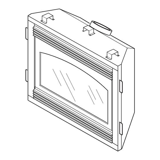
- Page 21 FIREPLACE INSTALLATION Continued REMOVING/REPLACING GLASS DOOR You must remove glass door to install op- tional brick liners, logs, lava rock, and em- ber material. CAUTION: Do not operate this fireplace with a broken glass door panel. Do not operate this fire- place without the glass door panel securely in place.
- Page 22 DIRECT-VENT FIREPLACE (NATURAL/PROPANE/LP) FIREPLACE INSTALLATION Continued INSTALLING OPTIONAL BRICK LINER D8037A/D8041 WARNING: If fireplace has been running, turn off and un- plug fireplace. Let cool before installing brick liner. This brick liner kit is optional. You may purchase brick liner from your local dealer or see Accessories, page 33.
- Page 23 FIREPLACE INSTALLATION Continued INSTALLING LOGS, LAVA ROCK AND GLOWING EMBERS WARNING: Failure to position the parts in accordance with these diagrams or failure to use only parts specifically approved with this heater may result in property damage or personal injury. Each log is marked with a number.
- Page 24 DIRECT-VENT FIREPLACE (NATURAL/PROPANE/LP) FIREPLACE INSTALLATION Continued Fireplace Models DDV37N/P(A, B) and DDV41N/P(A, B) Place log #1 (back log) on grate. Make sure the lower middle section of the log fits securely into the open area in back of grate (see Figure 50). Place log #2 (two log assembly) onto pins on left front and middle section of the front burner (see Figure 51).
-
Page 25: Operating Fireplace
OPERATING FIREPLACE FOR YOUR SAFETY READ BEFORE LIGHTING WARNING: If you do not fol- low these instructions exactly, a fire or explosion may result caus- ing property damage, personal injury or loss of life. A. This appliance has a pilot which must be lighted by hand. -
Page 26: Inspecting Burners
DIRECT-VENT FIREPLACE (NATURAL/PROPANE/LP) OPERATING FIREPLACE Continued OPTIONAL REMOTE OPERATION Note: The GHRC receiver and hand- held remote control accessory must be purchased separately. (See Accessories on page 33.) Follow instructions included with the remote control. NOTICE: You must light the pilot before using the hand-held re- mote control unit. -
Page 27: Cleaning And Maintenance
INSPECTING BURNERS Continued Figure 57 shows a typical flame pattern for DDV37N/P(A,B), and DDV41N/P(A,B) models. Figure 58 shows a typical flame pattern for BDV37N/P(A,B), and BDV41N/P(A,B). If burner flame pattern differs from that described: • turn fireplace off (see To Turn Off Gas to Appliance, page 25) •... -
Page 28: Troubleshooting
DIRECT-VENT FIREPLACE (NATURAL/PROPANE/LP) TROUBLESHOOTING Note: For additional help, visit DESA International’s technical service web site at www.desatech.com. Note: All troubleshooting items are listed in order of operation. OBSERVED PROBLEM When ignitor button is pressed, there is no spark at pilot... - Page 29 TROUBLESHOOTING Continued OBSERVED PROBLEM Burner does not light after pilot is lit Delayed ignition burner Burner backfiring during combustion Slight smoke or odor during initial operation Heater produces a whistling noise when burner is lit Glass soots Fireplace produces a clicking/ticking noise just after burners are lit or shut off Remote does not function 105539...
- Page 30 DIRECT-VENT FIREPLACE (NATURAL/PROPANE/LP) TROUBLESHOOTING Continued WARNING: If you smell gas • Shut off gas supply. • Do not try to light any appliance. • Do not touch any electrical switch; do not use any phone in your building. • Immediately call your gas supplier from a neighbor’s phone. Follow the gas supplier’s instructions.
-
Page 31: Replacement Parts
If they can not supply original replacement part(s), call DESA International’s Techni- cal Service Department at 1-800-DESA LOG (1-800-337-2564). When calling DESA International, have ready • your name • your address • model and serial numbers of your fireplace • how fireplace was malfunctioning •... -
Page 32: Specifications
DIRECT-VENT FIREPLACE (NATURAL/PROPANE/LP) SPECIFICATIONS BDV/DDV37N(A,B) Gas Type Ignition Manifold Pressure Minimum Inlet Supply Pressure Dimension, Inches/mm (HxWxD) Fireplace Carton Weight, lbs/kg Fireplace Shipping ® BDV/DDV37P(A,B) 16,000/22,000 Btu/h 16,000/20,000 Btu/h Natural Propane/LP Piezo Piezo 3.5" w.c. 10.0" w.c. 4.5" w.c. 11.0" w.c. 33"... - Page 33 ACCESSORIES Purchase these fireplace accessories from your local dealer. If they can not supply these accessories, call DESA International’s Sales Department at 1-800-432-2382. for information. You can also write to the ad- dress listed on the back page of this manual.
-
Page 34: Illustrated Parts Breakdown
DIRECT-VENT FIREPLACE (NATURAL/PROPANE/LP) ILLUSTRATED PARTS BREAKDOWN BDV37N(A,B) BDV41N(A,B) 34-2 34-4 ® 34-3 34-1 11 (Included in Hardware Pack) 105539... -
Page 35: Parts List
PARTS LIST DIRECT-VENT FIREPLACE BDV37N(A,B) BDV41N(A,B) PART NUMBER DESCRIPTION 104547-02 Top Outer Casing-37" 104547-03 Top Outer Casing-41" 104474-02 Outer Casing-37" 104474-03 Outer Casing-41" 104548-02 Bottom Outer Casing-37" 104548-01 Bottom Outer Casing-41" 104479-12BR Firebox Assembly-37" 104479-11BR Firebox Assembly-41" M11084-26 Screw, Hex M11084-46 Screw, Hex 102455-04... - Page 36 DIRECT-VENT FIREPLACE (NATURAL/PROPANE/LP) ILLUSTRATED PARTS BREAKDOWN BDV37P(A,B) BDV41P(A,B) 34-2 34-4 ® 34-3 34-1 11 (Included in Hardware Pack) 105539...
- Page 37 PARTS LIST DIRECT-VENT FIREPLACE BDV37P(A,B) BDV41P(A,B) PART NUMBER DESCRIPTION 104547-02 Top Outer Casing-37" 104547-03 Top Outer Casing-41" 104474-02 Outer Casing-37" 104474-03 Outer Casing-41" 104548-02 Bottom Outer Casing-37" 104548-01 Bottom Outer Casing-41" 104479-12BR Firebox Assembly-37" 104479-11BR Firebox Assembly-41" M11084-26 Screw, Hex M11084-46 Screw, Hex 102455-04...
- Page 38 DIRECT-VENT FIREPLACE (NATURAL/PROPANE/LP) ILLUSTRATED PARTS BREAKDOWN DDV37N(A,B) DDV41N(A,B) ® 39-1 39-2 39-3 11 (Included in Hardware Pack) 105539...
- Page 39 PARTS LIST DIRECT-VENT FIREPLACE DDV37N(A,B) DDV41N(A,B) PART NUMBER DESCRIPTION 104547-02 Top Outer Casing-37" 104547-03 Top Outer Casing-41" 104474-02 Outer Casing-37" 104474-03 Outer Casing-41" 104548-02 Bottom Outer Casing-37" 104548-01 Bottom Outer Casing-41" 104479-14BR Firebox Assembly-37" 104479-13BR Firebox Assembly-41" M11084-26 Screw, Hex M11084-46 Screw, Hex 102455-04...
- Page 40 DIRECT-VENT FIREPLACE (NATURAL/PROPANE/LP) ILLUSTRATED PARTS BREAKDOWN DDV37P(A,B) DDV41P(A,B) ® 39-1 39-2 39-3 11 (Included in Hardware Pack) 105539...
- Page 41 PARTS LIST DIRECT-VENT FIREPLACE DDV37P(A,B) DDV41P(A,B) PART NUMBER DESCRIPTION 104547-02 Top Outer Casing-37" 104547-03 Top Outer Casing-41" 104474-02 Outer Casing-37" 104474-03 Outer Casing-41" 104548-02 Bottom Outer Casing-37" 104548-01 Bottom Outer Casing-41" 104479-14BR Firebox Assembly-37" 104479-13BR Firebox Assembly-41" M11084-26 Screw, Hex M11084-46 Screw, Hex 102455-04...
-
Page 42: Warranty Information
DESA International warrants this product to be free from defects in materials and components for four (4) years from the date of first purchase, provided that the product has been properly installed, operated and maintained in accordance with all applicable instructions. To make a claim under this warranty the Bill of Sale or cancelled check must be presented.
Need help?
Do you have a question about the B) and is the answer not in the manual?
Questions and answers