Table of Contents
Advertisement
Quick Links
FORM NO.:6U6K-B01E-NB-EN
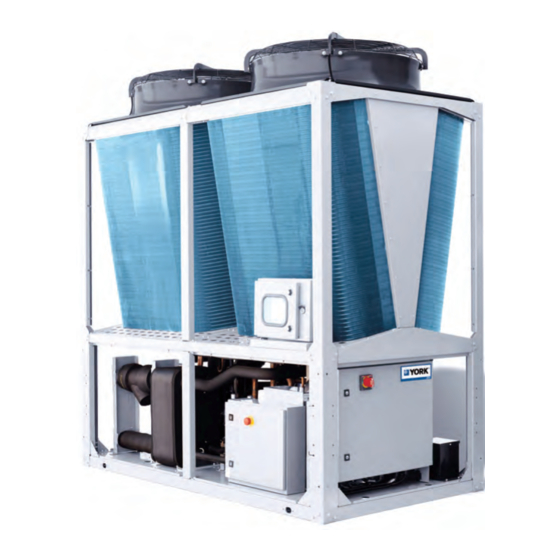
AIR-COOLED CHILLER
AND HEAT PUMP
INSTALLATION,COMMISSIONING,
Supersedes: 6U6K-B01E-NA-EN
FORM NO.: 6U6K-B01E-NB-EN
OPERATION & MAINTENANCE
YMAA / YMPA 0045-0260
AIR-COOLED CHILLER AND HEAT PUMP
50Hz
44-255kW
R410A
Issue Date:
February 26, 2018
JOHNSON CONTROLS
1
Cooke Industries - Phone: +64 9 579 2185
Email: sales@cookeindustries.co.nz
Web: www.cookeindustries.co.nz
Advertisement
Table of Contents
Troubleshooting

Related Manuals for York YMPA 0065


Summarization of Contents
Section 1 - General Information and Safety
General Safety Guidelines
Covers general safety guidelines and applicable standards for the unit, including warnings and precautions.
Safety Labels
Describes the meaning of various safety labels affixed to the unit to indicate potential hazards.
Section 2 - Product Description
Compressor
Details the DC inverter and fixed speed scroll compressors used in the unit, including their features.
Hydro Kit
Explains the factory-fitted Hydro Kit suitability and components for water and glycol systems.
Table 1 - Product Identification Number (PIN)
Explains the Product Identification Number (PIN) structure, options, and their meanings.
Section 3 - Handling and Storage
Lifting the Unit
Details how to safely lift the unit using provided holes and lifting lugs, including spreader bars.
Moving the Unit by Forklift Trucks
Provides guidance on moving the unit using forklift trucks for different models and configurations.
Section 4 - Installation
Location and Clearances
Discusses suitable installation locations and required clearances for optimal unit performance and access.
Chilled Liquid Piping
General guidelines for connecting the chilled liquid piping system, including best practices and component recommendations.
Wiring
Covers field wiring requirements, power wiring, and unit wiring diagrams for proper electrical connections.
Section 5 - Technical Data
Operational Limitations
Lists temperature and flow limits for cooling and heating operations, and voltage limitations.
Electrical Data
Provides detailed electrical data for YMAA/YMPA units with and without hydro kits.
Wiring Diagram
Illustrates various wiring diagrams for unit components, models, and microboards.
DIP Switch Setting
Explains microboard and wire controller DIP switches for setting addresses, models, and configurations.
Dimensions
Shows dimensional drawings for various YMAA/YMPA models and configurations (with/without hydro kit).
Isolator Details – One Inch Deflection Spring Isolator Cross-Reference
Details and cross-references one-inch deflection spring isolators (MHS and MHD types).
Section 6 - Commissioning
Preparation – Power Off
Basic checks to be performed with the unit's power switched OFF before startup.
Checking Superheat and Subcooling
Details how to check and adjust superheat and subcooling for refrigerant circuits.
Start-Up Checklist
Checklist for system checks before initial startup, including unit checks and compressor heater operation.
Section 7 - OptiView LT Operation
Main Interface
Describes the main interface layout, divided into five areas for status and control.
Privilege Management
Explains how to access and manage different privilege levels (Viewer, Operator, Service) using passwords.
System Setpoints
Lists parameters that can be set by Operator and Service levels for unit operation.
Section 8 - Wire Controller Operation
Interface
Describes the user interface of the wire controller, including display areas and touch keys.
Basic Operations
Instructions on starting/stopping the unit, setting modes, and liquid temperature setpoints.
Advanced Operations
Instructions for setting date/time, schedule timers, and other advanced controller functions.
Section 9 - Unit Operation
Capacity Control
Explains how the unit controls capacity based on permissive inputs, schedules, and temperature changes.
Compressor Sequencing
Manages compressor loading and unloading to equalize run hours and optimize system performance.
Defrost Controls
Systems and setpoints for removing frost and ice from ambient coils to improve efficiency.
Section 10 - Service and Troubleshooting
Analog and Digital Inputs
Lists and defines analog and digital inputs connected to the microboard for system monitoring.
Troubleshooting
Lists common problems, their causes, and solutions for diagnosing and resolving unit issues.
Section 11 - Maintenance
Compressors
Information regarding compressor oil type, checking, and potential issues like internal arcing.
Modbus Protocol
Defines Modbus protocol parameters, including data flow, temperature, pressure, and access mechanisms.
Table 46 – Fault Definitions
Defines faults related to sensors and system status, categorized by fault words for diagnostics.
Table 47 – VSD Fault Definitions
Defines faults related to the Variable Speed Drive (VSD) system, including sensor and communication errors.
BACnet Point Table
Lists BACnet points for reading and writing data, including data types, units, and ranges.
Need help?
Do you have a question about the YMPA 0065 and is the answer not in the manual?
Questions and answers