Table of Contents
Advertisement
SERVICE MANUAL
Ver. 1.4 2012.07
• The tuner and CD sections have no adjustments.
AUDIO POWER SPECIFICATIONS
(US model)
CEA2006 Standard
Power Output: 17 Watts RMS 4 at
4 Ohms < 1 % THD + N
SN Ratio: 80 dBA
(reference: 1 Watt into 4 Ohms)
Tuner section
FM
Tuning range:
US, CND, AR model: 87.5 – 107.9 MHz
AEP, UK, EA model:
87.5 – 108.0 MHz
E, MX, KR, IND model:
87.5 – 108.0 MHz (at 50 kHz step)
87.5 – 108.0 MHz (at 100 kHz step)
87.5 – 107.9 MHz (at 200 kHz step)
RU model:
FM1/FM2: 87.5 – 108.0 MHz (at 50 kHz)
FM3: 65 – 74 MHz (at 30 kHz)
FM tuning step:
E, MX, KR, IND model:
50 kHz/100 kHz/200 kHz switchable
Antenna (aerial) terminal:
External antenna (aerial) connector
Intermediate frequency: 25 kHz
Usable sensitivity: 8 dBf
Selectivity: 75 dB at 400 kHz
Signal-to-noise ratio: 80 dB (stereo)
Separation: 50 dB at 1 kHz
Frequency response: 20 – 15,000 Hz
9-893-214-05
Sony Corporation
2012G33-1
©
2012.07
Published by Sony Techno Create Corporation
CDX-GT40U/GT40UW/GT42UE/
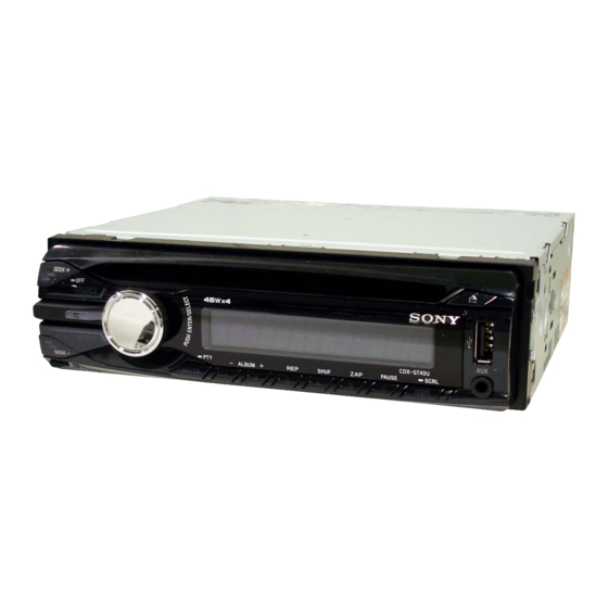
Photo: CDX-GT40U: AEP, UK model
SPECIFICATIONS
AM (US, CND, E, MX, AR, KR, IND model)
Tuning range:
US, CND, AR model: 530 – 1,710 kHz
E, MX, KR, IND model:
531 – 1,602 kHz (at 9 kHz step)
530 – 1,710 kHz (at 10 kHz step)
AM tuning step:
E, MX, KR, IND model:
9 kHz/10 kHz switchable
Antenna (aerial) terminal:
External antenna (aerial) connector
Intermediate frequency:
US, CND, AR model:
9,115 kHz or 9,125 kHz/5 kHz
E, MX, KR, IND model:
9,124.5 kHz or 9,115.5 kHz/4.5 kHz
(at 9 kHz step)
9,115 kHz or 9,125 kHz/5 kHz
(at 10 kHz step)
Sensitivity: 26 V
GT44U/GT45U/GT47UE
Model Name Using Similar Mechanism
CD Drive Mechanism Type
Optical Pick-up Name
MW/LW (AEP, RU, UK model)
MW (EA model)
Tuning range:
MW: 531 – 1,602 kHz
LW: 153 – 279 kHz (AEP, RU, UK model)
Antenna (aerial) terminal:
External antenna (aerial) connector
Intermediate frequency:
9,124.5 kHz or 9,115.5 kHz/4.5 kHz
Sensitivity: MW: 26 V
LW: 45V (AEP, RU, UK model)
SW (EA model)
Tuning range:
SW1: 2,940 – 7,735 kHz
SW2: 9,500 – 18,135 kHz
(except for 10,140 – 11,575 kHz)
Antenna (aerial) terminal:
External antenna (aerial) connector
Intermediate frequency:
9,124.5 kHz or 9,115.5 kHz/4.5 kHz
Sensitivity: 26 μV
US, Canadian, E, Mexican, Argentina, Korean, Indian model
FM/AM COMPACT DISC PLAYER
FM/MW/LW COMPACT DISC PLAYER
FM/MW/SW COMPACT DISC PLAYER
US Model
CDX-GT40U/GT40UW
Canadian Model
CDX-GT40U
AEP Model
UK Model
CDX-GT40U/GT44U
E Model
CDX-GT45U
Russian Model
CDX-GT40U/GT42UE/GT47UE
Indian Model
CDX-GT44U
NEW
MG-101CA-188
DAX-25A
CD player section
Signal-to-noise ratio: 120 dB
Frequency response: 10 – 20,000 Hz
Wow and fl utter: Below measurable limit
USB Player section
Interface: USB (Full-speed)
Maximum current: 1 A
Power amplifi er section
Outputs: Speaker outputs
Speaker impedance: 4 – 8 ohms
Maximum power output:
US, CND, E, EA, MX, AR, KR, IND model:
52 W 4 (at 4 ohms)
AEP, RU, UK model: 45 W 4 (at 4 ohms)
– Continued on next page –
AEP, Russian, UK model
Saudi Arabia model
Advertisement
Table of Contents

Related Manuals for Sony GT47UE


Summarization of Contents
CDX-GT40U/GT40UW/GT42UE/GT44U/GT45U/GT47UE Service Manual
Specifications Overview
Details technical specifications for the CD player section, including tuner and CD player capabilities.
Audio Power Specifications
Outlines the audio power output and signal-to-noise ratio according to CEA2006 standard.
General Information and Connections
General Unit Specifications
Provides overall unit specifications including dimensions, weight, and power requirements.
Wiring and Connection Diagram
Illustrates the necessary connections for power, speakers, and external components.
Service Notes and Handling Precautions
Optical Pick-up and Laser Diode Handling
Provides critical handling instructions for the optical pick-up and laser diode to prevent damage.
Extension Cable and Service Position
USB and AUX Connector Replacement and Cleaning
Details the procedure for replacing USB/AUX connectors and cleaning internal connectors.
Main Board and System Controller Replacement
Destination Setting Procedure
Explains how to set the destination code after replacing the main board or system controller.
Mechanism Deck (MG-101CA-188) Former and New
New/Former Discrimination Methods
Provides methods to distinguish between former and new types of the mechanism deck.
LCD Driver IC (IC901) on Key Board Changes
Key Board New/Former Discrimination
Details methods to identify new or former types of the key board and its components.
Disassembly Procedures
Sub Panel Assembly Disassembly
Step-by-step guide for disassembling the sub panel assembly.
CD Mechanism Block and Main Board Disassembly
Instructions for removing the CD mechanism block and main board.
Servo Board Replacement
Procedure for replacing the servo board, including notes on former/new types.
Optical Pick-up Section and Assembly
Details on disassembling and assembling the optical pick-up section.
Diagrams and Schematics
Block Diagram - Main and Display Sections
Provides block diagrams for the main and display sections of the unit.
Waveforms and Diagram Notes
Explains waveform conventions and provides notes for reading diagrams.
Printed Wiring Board Layouts
Shows the layout of printed wiring boards for the main unit.
Schematic Diagrams - Main Section
Detailed schematic diagrams covering the main section of the unit.
Key Board Diagrams and IC Pin Descriptions
Key Board Printed Wiring and Schematics
Illustrates the printed wiring and schematic diagrams for the key board.
IC Block Diagrams and Pin Functions
Provides block diagrams and detailed pin descriptions for key ICs.
Exploded Views of Unit Sections
Main Section Exploded View
Visual breakdown of the main section, showing component parts and their references.
Front Panel Section Exploded View
Visual breakdown of the front panel section, listing all associated parts.
CD Mechanism Section Exploded View
Detailed exploded view of the CD mechanism section.
Electrical Parts Lists
Key Board Electrical Parts List
Comprehensive list of electrical components used in the key board.
Main Board Electrical Parts List
Detailed list of electrical components for the main board.
Installation and Connection Parts
Lists parts required for installation and various connection accessories.
Supplement-1: Saudi Arabia Model Main Board
Printed Wiring Board for Saudi Arabia Model
Provides specific printed wiring board details for the Saudi Arabia model.
Supplement-2: Key Board Changes
Key Board Changes (Suffix-21/-22) Overview
Details changes made to the key board, including part number and IC revisions.
New/Former Discrimination Methods
Unit and Key Board Discrimination
Explains methods to distinguish between new and former unit and key board parts.
Key Board Wiring and Schematics
Key Board Printed Wiring Diagram
Layout of the key board's printed wiring.
Key Board Schematic Diagrams
Detailed schematic for the key board, showing component connections.
Electrical Parts List - Key Board
Key Board Component Details
Lists capacitors, connectors, diodes, LEDs, switches, transistors, and resistors for the key board.
Key Board Switches and Resistors
Specific listing of switches and resistors used on the key board.
Need help?
Do you have a question about the GT47UE and is the answer not in the manual?
Questions and answers