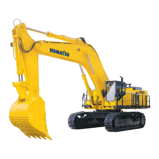
Summarization of Contents
00 Index and Foreword
Composition of shop manual
Outlines the structure and components of the shop manual for effective organization and use.
Table of contents
Provides a detailed listing of all sections and their corresponding page numbers for quick navigation.
Foreword and general information
Offers introductory remarks, machine model details, and general guidance for manual users.
40 Troubleshooting
Failure code table and fuse locations
Provides a guide to failure codes, their meanings, and the location of fuses for diagnostic purposes.
General information on troubleshooting
Offers an overview of the troubleshooting process, including key principles and steps.
Troubleshooting by failure code (Display of code), Part 1
Guides users through troubleshooting specific failure codes related to the engine and its systems.
50 Disassembly and assembly
General information on disassembly and assembly
Provides essential guidelines and precautions for performing disassembly and assembly tasks.
Engine and cooling system, Part 1
Details the procedures for removing and installing engine and cooling system components.
Engine and cooling system, Part 2
Covers disassembly and assembly for additional engine and cooling system parts.
Power train
Explains the disassembly and assembly procedures for power train components.
Undercarriage and frame
Details the disassembly and assembly of the undercarriage and frame components.
90 Diagrams and drawings
Hydraulic circuit diagrams
Presents schematic diagrams of the machine's hydraulic circuits for system understanding.
Electrical diagrams and drawings
Provides schematic diagrams of the machine's electrical circuits for troubleshooting and repair.
01 Specification
Specification and technical data
Presents detailed specifications and technical data for the machine, serving as a reference.
10 Structure, function and maintenance standard
Engine and cooling system
Describes the structure, function, and maintenance standards for the engine and cooling system components.
Power train
Details the structure, function, and maintenance standards for the power train components.
Undercarriage and frame
Explains the structure, function, and maintenance standards for the undercarriage and frame.
Air system
Covers the structure, function, and maintenance standards for the machine's air system.
20 Standard value table
Standard service value table
Lists standard service values for judging the condition of parts during testing and adjustment.
30 Testing and adjusting
Testing and adjusting, Part 1
Covers initial testing and adjusting procedures, including tools and methods.
Testing and adjusting, Part 2
Details further testing and adjusting procedures for various machine systems and components.
Testing and adjusting, Part 3
Explains advanced testing and adjusting techniques for hydraulic and mechanical systems.
Testing and adjusting, Part 4
Covers testing and adjusting related to electronic control units and system diagnostics.
Testing and adjusting, Part 5
Details procedures for testing and adjusting machine monitor systems and related components.
Testing and adjusting, Part 6
Focuses on specific testing and adjusting procedures, including clinic services.
Safety Notice
General precautions
Covers essential safety advice for machine operation and maintenance, emphasizing careful reading of manuals.
Safety points
Lists critical safety considerations and practices, including good arrangement, correct attire, and protective gear.
How to read the shop manual
Composition of shop manual
Explains how the manual is divided into sections for understanding and service.
00 Index and foreword
Describes the initial section covering manual lists, table of contents, safety, and basic information.
01 Specification
Details the machine's specifications and technical data for reference.
10 Structure, function and maintenance standard
Explains component structure, function, and maintenance standards for repair guidance.
20 Standard value table
Lists standard values for new machines and judgment criteria for testing and adjustments.
30 Testing and adjusting
Covers measuring instruments, methods, and procedures for testing and adjusting machine components.
40 Troubleshooting
Provides methods for identifying failed parts and repairing them based on failure modes.
50 Disassembly and assembly
Explains procedures for removing, installing, and assembling components with precautions.
90 Diagrams and drawings
Provides hydraulic and electrical circuit diagrams for system analysis.
Revision and distribution
Informs about how to obtain updates and revisions to the shop manual.
Handling of electric equipment and hydraulic component
Points to remember when handling electric equipment
Offers guidance on proper handling of wiring harnesses and connectors to prevent damage and ensure reliable connections.
Points to remember when handling hydraulic equipment
Emphasizes care in handling hydraulic systems to prevent contamination and ensure system longevity.
Precautions when carrying out operation
Precautions when carrying out removal work
Details safety measures and procedures to follow before and during the removal of machine components.
Precautions when carrying out installation work
Outlines essential steps and safety checks required when installing machine components and systems.
Precautions when completing the operation
Covers final checks and procedures after completing repair or maintenance operations, including refilling and system checks.
Method of disassembling and connecting push-pull type coupler
Type 1
Details the disconnection and connection procedures for the first type of push-pull couplers.
Type 2
Explains the disconnection and connection steps for the second type of push-pull hydraulic couplers.
Type 3
Describes the specific procedures for disconnecting and connecting the third type of push-pull hydraulic couplers.
Standard tightening torque table
Table of tightening torques for bolts and nuts
Provides recommended torque values for various bolts and nuts based on their thread diameter and across flats.
Table of tightening torques for split flange bolts
Lists specific torque values for split flange bolts used in hydraulic systems.
Table of tightening torques for O-ring boss piping joints
Specifies torque values for O-ring boss connections to ensure leak-free joints.
Table of tightening torques for O-ring boss plugs
Provides torque specifications for O-ring boss plugs to maintain seal integrity.
Table of tightening torques for hoses (taper seal type and face seal type)
Lists torque values for tightening hoses with taper seal and face seal types.
Table of tightening torques for face seal joints
Details torque specifications for face seal joints commonly used in engine applications.
Table of tightening torques for 102, 107 and 114 engine series (Bolts and nuts)
Specifies torque values for bolts and nuts used in specific engine series for proper assembly.


Need help?
Do you have a question about the PC1250SP-8 Backhoe and is the answer not in the manual?
Questions and answers