Table of Contents
Advertisement
Quick Links
Operation &
Maintenance Manual
PC1250
PC1250SP
HYDRAULIC EXCAVATOR
WARNING
Unsafe use of this machine may cause serious injury or
death. Operators and maintenance personnel must read
this manual before operating or maintaining this
machine. This manual should be kept inside the cab for
reference and periodically reviewed by all personel who
will come into contact with the machine.
EENAM03651
-11
-11
ORIGINAL INSTRUCTIONS
Advertisement
Chapters
Table of Contents

Related Manuals for Komatsu PC1250-11


Summary of Contents for Komatsu PC1250-11
- Page 1 Operation & EENAM03651 Maintenance Manual PC1250 PC1250SP HYDRAULIC EXCAVATOR WARNING ORIGINAL INSTRUCTIONS Unsafe use of this machine may cause serious injury or death. Operators and maintenance personnel must read this manual before operating or maintaining this machine. This manual should be kept inside the cab for reference and periodically reviewed by all personel who will come into contact with the machine.
-
Page 3: Foreword
Komatsu or Ko- matsu approved rebuilt parts or assemblies or others parts of equivalent quality, and that the engine be serviced by an authorized Komatsu distribu- tor. Failure to follow these recommendations could result in ineffective serv- ice, damage to the product or safety risks (including personal injury or death). -
Page 4: Read This Manual
Keep it in the magazine box on the left side of the operator's seat. If this manual is lost or damaged, contact Komatsu or your Komatsu distributor and tell them about the machine model name and the serial No. immediately to arrange for its replacement. -
Page 5: Komatsu Machine Operator Privacy Policy
Belgium, with registered office at 1800 Vilvoorde, Belgium, Mechelsesteenweg 586, registered in Brussels un- der number RPR/CER(0)404.968.268 ("Komatsu Europe", together with the other Komatsu subsidiaries in the EEA referred to as "we" or "us"). Komatsu Europe acts as Komatsu's representative in the EU with respect to MMS. - Page 6 FOREWORD • pictures, videos and sound recordings 4. Why is your personal data processed? When you use Komatsu machines equipped with MMS, your personal data are processed for the following rea- sons: (a) Safety and security (b) Warranty (c) Misuse and theft prevention...
- Page 7 (30) days after having received the request. If you have any complaint regarding the processing of your personal data by Komatsu or Komatsu Europe via MMS, you may always contact us via the e-mail address mentioned in the first paragraph of this clause. If you...
-
Page 8: Safety Information
SAFETY INFORMATION FOREWORD SAFETY INFORMATION To enable you to use the machine safely, and to prevent personal injury to operators, service personnel or by- standers, the precautions and warnings included in this manual and the safety signs attached to the machine must always be observed. -
Page 9: Noise
FOREWORD NOISE NOISE This label indicating the machine noise level is affixed on the machine. • Sound pressure level at the operator’s station, measured according to ISO 6396 (Dynamic test method, simulated working cycle). The maximum value of the standard deviation of the meas- ured time-averaged A-weighted emission sound pressure level at the operator’s position is 2.5dB, in accordance with ISO 11201... -
Page 10: Vibration Levels
VIBRATION LEVELS FOREWORD VIBRATION LEVELS When used for its intended purpose, levels of vibration for the earth-moving machine transmitted from the oper- ator's seat are lower than or equal to the tested vibrations for the relative machinery class in compliance with ISO 7096. - Page 11 FOREWORD VIBRATION LEVELS • Do not repeatedly handle and lift loads...
-
Page 12: Introduction
INTRODUCTION FOREWORD INTRODUCTION MAIN USE OF MACHINE This Komatsu machine is designed to be used mainly for the following work: • Digging work • Ditching work • Loading work • Leveling work For details of the work procedure, see OPERATION, “RECOMMENDED APPLICATIONS”. - Page 13 FOREWORD INTRODUCTION This machine maintains a proximity visibility of a height of 1.2 m at a point 1 m away from the outside surface of the machine, and a visibility for a radius of 12 m. 1-11...
- Page 14 INTRODUCTION FOREWORD To assist with job site organisation during use of this machine, a visibility map is provided that shows an approxi- mation of any masking to visibility between the 1 m rectangular boundary and the 24 m test circle. Based upon the information supplied in the visibility map the site operator may wish to provide additional meas- ures where it is felt necessary or provide additional instruction to personnel.
-
Page 15: Engine Technology To Conform Exhaust Gas Emission
EMISSION About Engine Technology This engine technology conforms the EU Stage IV emission regulation in the European Union by the Komatsu Diesel Particulate Filter (KDPF). Komatsu Diesel Particulate Filter (KDPF): A device which captures diesel particular matter or soot in the ex- haust gas to purify exhaust gas. -
Page 16: Product Information
PRODUCT INFORMATION FOREWORD PRODUCT INFORMATION When requesting service or ordering replacement parts, inform your Komatsu distributor of the following items. LOCATION OF PRODUCT IDENTIFICATION NUMBER (PIN)/MACHINE SERI- AL NO. PLATE It is located on the right bottom of the operator's cab. -
Page 17: Fluorinated Greenhouse Gases
YOUR MACHINE SERIAL NUMBERS AND DISTRIBUTOR Machine serial No. Engine serial No. Product identification number (PIN) Manufacturers name: KOMATSU LTD. Address: 2-3-6 Akasaka Minato-ku, Tokyo 107-8414 Japan Authorised representative: KOMATSU EUROPE INT. Address: Mechelsesteenweg 586 B-1800 Vilvoorde Belgium Distributor name Address Service personnel Phone/Fax 1-15... -
Page 18: Serial Plate
SERIAL PLATE FOREWORD SERIAL PLATE EI000001 MACHINE DESIGNATION/TYPE ENGINE POWER SERIAL NUMBER PRODUCT IDENTIFICATION NUMBER YEAR OF CONSTRUCTION MANUFACTURER OPERATING MASS AUTHORISED REPRESENTATIVE 1-16... -
Page 19: Declaration Of Conformity
FOREWORD DECLARATION OF CONFORMITY DECLARATION OF CONFORMITY The manufacturer/Authorised representative The manufacturer Authorised representative KOMATSU LTD. KOMATSU EUROPE INT. 2-3-6 Akasaka Mechelsesteenweg 586 Minato-ku, Tokyo 107-8414 B-1800 Vilvoorde Japan Belgium Declares that this machine: PC1250-11 PC1250SP-11 Fulfils all the relevant provisions of following EC Directives:... -
Page 20: Table Of Contents
TABLE OF CONTENTS FOREWORD TABLE OF CONTENTS FOREWORD..............................1-1 READ THIS MANUAL ..........................1-2 KOMATSU MACHINE OPERATOR PRIVACY POLICY ................1-3 SAFETY INFORMATION .......................... 1-6 NOISE............................... 1-7 VIBRATION LEVELS ..........................1-8 VIBRATION - OPERATING CONDITION ................... 1-8 GUIDE TO REDUCE VIBRATION LEVELS ON MACHINE ..............1-8 INTRODUCTION ............................ - Page 21 PRECAUTIONS FOR SEVERE JOB CONDITION................. 3-241 PRECAUTIONS FOR DISCHARGED BATTERY ................3-242 OTHER TROUBLE......................... 3-246 MAINTENANCE............................... 4-1 PRECAUTIONS FOR MAINTENANCE ..................... 4-2 CHECK SERVICE METER READING ....................4-2 KOMATSU GENUINE REPLACEMENT PARTS ................4-2 KOMATSU GENUINE LUBRICANTS ....................4-2 1-19...
- Page 22 EVERY 8000 HOURS MAINTENANCE ................... 4-83 EVERY 9000 HOURS MAINTENANCE ................... 4-83 SPECIFICATIONS ............................5-1 SPECIFICATIONS ............................ 5-2 SPECIFICATIONS: PC1250-11......................5-2 SPECIFICATIONS: PC1250SP-11 ..................... 5-3 ATTACHMENTS AND OPTIONS ........................6-1 PRECAUTIONS FOR USING ATTACHMENT AND OPTIONS..............6-2 PRECAUTIONS WHEN SELECTING ....................6-2 READ THE OPERATION AND MAINTENANCE MANUAL THOROUGHLY........
- Page 23 CONSUMABLE PARTS ........................7-4 RECOMMENDED FUEL, COOLANT, AND LUBRICANT ................7-6 LUBRICATION CHART ........................7-6 USE OF FUEL, COOLANT AND LUBRICANTS TO ACCORDING TO AMBIENT TEMPERATURE ................................7-8 RECOMMENDED BRANDS AND QUALITIES OTHER THAN KOMATSU GENUINE OILS ....7-9 INDEX................................8-1 1-21...
-
Page 25: Safety
SAFETY Please read and make sure that you fully understand the precautions descri- bed in this manual and the safety labels on the machine. When operating or servicing the machine, always follow these precautions strictly. -
Page 26: Safety Labels
If the safety labels are damaged, lost, or cannot be read properly, replace them with new ones. For details of the part numbers for the safety labels, see this manual or the actual label, and place an order to your Komatsu distributor. •... -
Page 27: Location Of Safety Labels
SAFETY SAFETY LABELS LOCATION OF SAFETY LABELS 1. Caution for operation, inspection and maintenance 2. Caution before operating... -
Page 28: Contents Of Safety Labels
SAFETY LABELS SAFETY 3. Caution when leaving operator's seat 12. Caution against falling 4. Caution for electric cables 13. Caution against falling 5. Caution for control pattern 14. Caution when swinging and traveling in reverse 6. Caution for high-temperature coolant and hydraulic 15. - Page 29 SAFETY SAFETY LABELS Caution when leaving operator's seat “09654-A0641” • Sign indicates a hazard of being caused or run over by un- expected moving of stopped machine. • Lower the work equipment to ground, move the lock lever to LOCK position and take key with you before leaving ma- chine.
- Page 30 SAFETY LABELS SAFETY Caution for high-temperature coolant and hy- draulic oil “09653-A0481” • Never remove the cap when the engine is at operating (high) temperature. Steam or high temperature oil blowing up from the radiator or hydraulic tank, will cause personal injury and/or burns.
- Page 31 SAFETY SAFETY LABELS Stop rotation during inspection and mainte- nance “09667-A0481” • Sign indicates a hazard of rotating parts, such as belt. • Turn off before inspection and maintenance. Emergency escape “09844-00050” • This is an emergency exit when the cab door will not open. In emergency, smash the window pane with an equipped hammer and get through there.
- Page 32 SAFETY LABELS SAFETY Caution against falling “09805-C0881” • Sign indicates a hazard of falling. • Do not stand on this place here. Caution when swinging and traveling in re- verse “09833-A0881” • When swinging or backing up excavator, press button to change display mode on monitor so you can see rear and side of machine.
- Page 33 SAFETY SAFETY LABELS Caution for work equipment “09134-A1681” • Sign indicates a hazard of being hit by the working device of the machine. • Keep away from machine during operation. Caution for high-pressure fuel “6271–81–2980” • When the engine is running, high-pressure fuel is generat- ed in the engine fuel piping.
- Page 34 SAFETY LABELS SAFETY Caution for high-temperature resistance “09817–K064B” • Sign indicates a burn hazard from touching heated parts, such as engine, motor, or muffler during or right after oper- ation. • Never touch when hot. 2-10...
-
Page 35: General Precautions Common To Operation And Maintenance
If any abnormality or problem is found, contact your Komatsu distributor. PRECAUTIONS BEFORE STARTING OPERATION ENSURE SAFE OPERATION •... -
Page 36: Precautions To Prevent Fire
GENERAL PRECAUTIONS COMMON TO OPERATION AND MAINTE- NANCE SAFETY • If water gets into the electrical system, electric devices will cause malfunctions, and the machine will cause error. If the machine cause error, it may move unexpectedly and cause serious personal injury or death. When washing the machine with water or steam, do not allow the water or steam to come into direct contact with electrical compo- nents. - Page 37 Fire around the machine due to highly heated exhaust gas This machine is equipped with Komatsu Diesel Particulate Filter (hereafter KDPF). 2-13...
-
Page 38: Precautions When Getting On Or Off Machine
If there is any loose bolt on the handrail and step, tighten it securely. If the handrails and steps are damaged or deformed, they need to be repaired immediately. Ask your Komatsu dis- tributor to perform this work. •... - Page 39 GENERAL PRECAUTIONS COMMON TO OPERATION AND MAINTE- SAFETY NANCE • Never jump on or off the machine. Never get on or off a moving machine. • If the machine starts to move when there is no operator on the machine, do not jump on to the machine and try to stop it.
-
Page 40: Do Not Get Caught In Work Equipment
• If the protective structure is damaged or deformed by falling objects or by rolling over, its strength will be reduced and it will not be able to fulfill its function properly. In such cases, always consult your Komatsu distributor. -
Page 41: Protection Against Falling, Flying Or Intruding Objects
UNAUTHORIZED MODIFICATION • Komatsu will not be responsible for any personal injuries, product failures, physical loss or damage, or influ- ence on the environment resulting from modifications made without authorization from Komatsu. • Any modification made without authorization from Komatsu can create hazards. Before making a modifica- tion, consult your Komatsu distributor. -
Page 42: Precautions When Running Engine Inside Building
GENERAL PRECAUTIONS COMMON TO OPERATION AND MAINTE- NANCE SAFETY ceiling window is scratched and is not replaced, there is a danger that any rocks falling on it will cause it to break, leading to injury to the operator. PRECAUTIONS WHEN RUNNING ENGINE INSIDE BUILDING The engine exhaust gas contains substances that may damage your health or even cause death. -
Page 43: Precautions For Operation
SAFETY PRECAUTIONS FOR OPERATION PRECAUTIONS FOR OPERATION PRECAUTIONS FOR JOBSITE INVESTIGATE AND CONFIRM JOBSITE CONDITIONS On the jobsite, there are various hidden dangers that may lead to serious personal injury or death. Before start- ing operations, always check the following to confirm that there is no danger on the jobsite. •... - Page 44 PRECAUTIONS FOR OPERATION SAFETY VOLTAGE MIN. DISTANCE 750 kV to 1000 kV 13.8 m • To prepare for any possible emergencies, wear rubber shoes and gloves. Lay a rubber sheet on the opera- tor's seat, and be careful not to touch the chassis with any exposed part of your body. •...
-
Page 45: Start Engine
Always observe the regulations for jobsite and environmental standards. This machine does not contain asbestos, but any part which is not the genuine part, it has risk of containing asbestos. Always use Komatsu genuine parts. START ENGINE USE WARNING TAGS If there is a "DANGER! Do NOT operate!"... - Page 46 • Adjust the cameras to have a good rear view and a good view of surrounding area from the operator's seat. For the adjustment, please contact your Komatsu distribu- tor. • Adjust the armrest to a position for easier operation, and fix it securely.
-
Page 47: Precautions For Operation
SAFETY PRECAUTIONS FOR OPERATION • When disconnecting the jumper cables, take care not to bring the clips in contact with each other or with the machine. PRECAUTIONS FOR OPERATION CHECKS BEFORE OPERATION If the checks before starting are not performed properly, the machine will be unable to display its full perform- ance. - Page 48 PRECAUTIONS FOR OPERATION SAFETY • Always operate the machine only when seated on the operator's seat. • Before starting to move, check again that there is no people or obstacle in the surrounding area. • Before moving, sound the horn to warn people in the surrounding area.
- Page 49 SAFETY PRECAUTIONS FOR OPERATION • When passing over bridges or structures, check first that the structure is strong enough to support the weight of the machine. When passing on a public road, check with authorities concerned and observe their instruction. •...
-
Page 50: Prohibited Operations
PRECAUTIONS FOR OPERATION SAFETY • Do not turn on slopes or drive across slopes. Always go down to a flat place to change the position of the machine, then drive it on to the slope again. • Do not drive the machine on a slope covered with the steel plates. Even with slight slopes there is a hazard that the machine may slip. - Page 51 SAFETY PRECAUTIONS FOR OPERATION • Do not excavate too deeply under the front of the machine. The ground under the machine may collapse and cause the machine to fall. • For a quick escape in an emergency, set the tracks at right angles to the road shoulder or cliff with the sprocket at the rear when performing operations.
- Page 52 PRECAUTIONS FOR OPERATION SAFETY • Do not pass the bucket over the heads of other workers or over the operator's seat of dump trucks or other hauling equipment. There is a danger that the load may spill or the bucket may hit the dump truck and cause serious personal injury or death.
-
Page 53: Precautions For Transportation
• This machine may need to be divided into components for transportation depending on the regulation. When transporting the machine, consult your Komatsu distributor. PRECAUTIONS WHEN LOADING AND UNLOADING If handling is improper when loading or unloading the machine, it is dangerous that the machine may tip over or fall. -
Page 54: Towing And Being Towed
PRECAUTIONS FOR OPERATION SAFETY • When loading or unloading to an embankment or platform, make sure that it has suitable width, strength, and grade. • When swinging the upper structure on the loading platform, lower the work equipment, retract it, and per- form the operation slowly. - Page 55 SAFETY PRECAUTIONS FOR OPERATION • Do not use the work equipment or swing to pull the load in any direction. There is danger that the hook may break and the load come off, causing the work equipment to move suddenly and cause personal injury. •...
-
Page 56: Precautions For Maintenance
PRECAUTIONS FOR MAINTENANCE SAFETY PRECAUTIONS FOR MAINTENANCE PRECAUTIONS BEFORE STARTING INSPECTION AND MAINTENANCE DISPLAY WARNING TAG DURING INSPECTION AND MAINTENANCE During inspection and maintenance, always display the "DAN- GER! Do NOT operate!" warning tag. If there is a "DANGER! Do NOT operate!" warning tag dis- played, it means that someone is performing inspection and maintenance of the machine. - Page 57 END OF SERVICE LIFE • For safe dismantling of the machine at the end of service life, please contact your Komatsu distributor. STOP ENGINE BEFORE CARRYING OUT INSPECTION AND MAINTENANCE If you are caught or pinched between the work equipment during operation, or exposed to high-temperature or high-pressure liquids, it is dangerous and may cause serious personal injury or death.
- Page 58 PRECAUTIONS FOR MAINTENANCE SAFETY • Rotating parts such as the fan, fan belt are dangerous that they may easily catch a body part or an object someone wears. Be careful not to come close to the rotating part. • Never drop or insert tools or other objects into the fan, fan belt, or other rotating parts.
-
Page 59: Precautions For Check And Maintenance
SAFETY PRECAUTIONS FOR MAINTENANCE PRECAUTIONS WHEN WORKING UNDER MACHINE OR WORK EQUIPMENT Machine or work equipment may fall, and it is dangerous that serious personal injury or death may occur. Al- ways observe the following. • Make sure the hoists or hydraulic jacks you use are in good condition and strong enough to handle the weight of the component. - Page 60 PRECAUTIONS FOR MAINTENANCE SAFETY HANDLE BATTERY When checking and handling the battery, turn the starting switch to OFF position and check that the system op- erating lamp is not lit. Turn the battery disconnect switch to OFF position, and remove the key. Cleaning the battery Clean the battery with a cloth which is wet with water.
- Page 61 SAFETY PRECAUTIONS FOR MAINTENANCE PRECAUTIONS WHEN USING HAMMER When using a hammer, pins may come out or metal particles may be scattered. It is dangerous and may cause serious personal injury or death. Always observe the following. • When hitting pins or bucket teeth, broken pieces may be scattered, and it may cause personal injury to the people in the surrounding area.
- Page 62 If the hose or piping mounts are loose or oil or fuel is found to be leaking from the mount, stop operations and tighten to the specified torque. If any damaged or deformed hoses or piping are found, consult your Komatsu distributor. Replace the hose if any of the following problems are found.
- Page 63 If it is disassembled by mistake, the spring may shoot out and cause serious personal injury or death. If it is necessary to disassemble it, ask your Komatsu distributor to perform the work. HANDLE ACCUMULATOR AND GAS SPRING This machine is equipped with an accumulator.
- Page 64 • When disposing of the accumulator, the gas must be re- leased. Ask your Komatsu distributor to perform this work. PRECAUTIONS FOR COMPRESSED AIR • When performing cleaning with compressed air, there is a hazard of serious personal injury or death caused by flying dust or particles.
- Page 65 SAFETY PRECAUTIONS FOR MAINTENANCE • The material of these components naturally changes over time, and repeated use causes deterioration, wear, and fatigue. As a result, there is a hazard that these components may fail and cause serious personal injury or death. It is difficult to judge the remaining life of these components from external inspection or the feeling when operating, so always replace them at the specified interval.
-
Page 67: Operation
OPERATION Please read and make sure that you understand the SAFETY section before reading this section. -
Page 68: General View
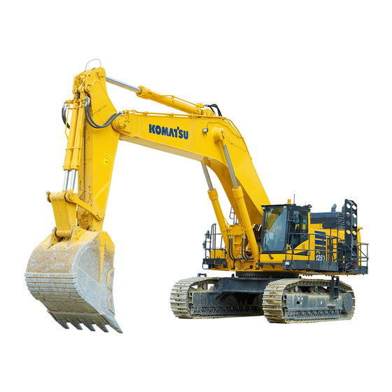
GENERAL VIEW OPERATION GENERAL VIEW MACHINE EQUIPMENT NAME (1) Bucket (8) Sprocket (2) Bucket link (9) Track frame (3) Bucket cylinder (10) Track shoe (4) Arm (11) Idler (5) Arm cylinder (12) Protective guard (6) Boom (13) Toolbox (7) Boom cylinder... - Page 69 OPERATION GENERAL VIEW Details of A, B, C, D (14) Komatsu Closed Crankcase Ventilation (hereafter (18) System operating lamp KCCV) ventilator (19) Circuit breaker (15) KDPF (20) Grease pump (16) Battery (21)KomVision camera (17) Battery disconnect switch...
-
Page 70: Cab Equipment Names
GENERAL VIEW OPERATION CAB EQUIPMENT NAMES (1) Front window (7) Fire extinguisher (if equipped) (2) Ceiling window (8) Emergency escape hammer (3) Door lock release lever (9) Magazine box (4) Drink box (10) Cup holder (5) Fuse (11) AUX (6) Auxiliary electric power (if equipped) (12) Ashtray... -
Page 71: Controls And Gauges Names
OPERATION GENERAL VIEW CONTROLS AND GAUGES NAMES (1) Radio (14) Machine push-up switch (2) Lock lever (15) Boom shock absorbing control switch (3) L.H. work equipment control lever (16) Lower wiper switch (machines equipped with fixed front window cab) (4) Travel pedal (17) Revolving lamp switch (if equipped) (5) Travel lever (18) Seat heater switch... - Page 72 GENERAL VIEW OPERATION MACHINE MONITOR EQUIPMENT NAME AA: Standard screen, BB: Check before starting screen, CC: Maintenance time warning screen (1) Wiper switch (21) Radiator coolant level caution lamp (2) Buzzer cancel switch (22) Seat belt caution lamp (3) Auto-deceleration switch (23) Engine stop pilot lamp (4) Hydraulic oil temperature gauge (24) Lock lever pilot lamp...
- Page 73 OPERATION GENERAL VIEW REMARK The above figure does not show all of the caution lamp symbols.
-
Page 74: Explanation Of Components
EXPLANATION OF COMPONENTS OPERATION EXPLANATION OF COMPONENTS The following is an explanation of devices necessary to operate the machine. To perform suitable operations correctly and safely, it is important to completely understand methods of operat- ing the equipment, and the meanings of the displays. EXPLANATION OF MACHINE MONITOR EQUIPMENT AA: Standard screen, EE: Warning or Error screen, DD: Guidance screen (1) Warning display... -
Page 75: Basic Operation Of Machine Monitor
OPERATION EXPLANATION OF COMPONENTS BASIC OPERATION OF MACHINE MONITOR BASIC OPERATION OF MACHINE MONITOR WHEN STARTING ENGINE IN NOR- MAL SITUATION • When the starting switch is turned to ON position, the starting screen GG is displayed. • After the starting screen GG is displayed for 2 seconds, the screen changes to the check before starting screen BB. - Page 76 EXPLANATION OF COMPONENTS OPERATION BASIC OPERATION OF MACHINE MONITOR WHEN STARTING ENGINE WHILE ENGINE SHUTDOWN SECONDARY SWITCH IS ON While engine shutdown secondary switch (1) is ON (engine is stopped), when the starting switch is turned to ON position, the screen shown in the figure is displayed and engine does not start.
- Page 77 EXPLANATION OF COMPONENTS End screen when any message has been re- ceived If there is any message from your Komatsu distributor, it is dis- played on the end screen. In this case, turn the starting switch to ON position to re-check the message, and if the message is requesting a response, make a reply to it.
- Page 78 Do not use it for the purpose of security enhancement. Komatsu cannot accept any responsibility for any loss or damage resulting from the wrong use of ID or unauthorized use of ID by a third party.
- Page 79 OPERATION EXPLANATION OF COMPONENTS BASIC OPERATION OF MACHINE MONITOR WHEN STARTING ENGINE IN AB- NORMAL SITUATION • If there is any abnormality when starting the engine, the check before starting screen BB changes to the maintenance time warning screen CC, warning screen FF, or error screen EE. •...
- Page 80 EXPLANATION OF COMPONENTS OPERATION If there is any error existing, “!” is displayed above the switch Press the switch F5 to check the detail of the error. Current Ab- normality screen is displayed. BASIC OPERATION OF MACHINE MONITOR WHEN TROUBLE OCCURS WHILE OPERATING MACHINE 3-14...
- Page 81 OPERATION EXPLANATION OF COMPONENTS • If any abnormality occurs during operation, the standard screen AA changes to the warning screen FF-(1) or the error screen EE. • After displaying the warning screen FF-(1) for 2 seconds, the screen automatically changes to the warning screen FF-(2).
- Page 82 EXPLANATION OF COMPONENTS OPERATION BASIC OPERATION OF MACHINE MONITOR WHEN OPERATING WORK EQUIP- MENT, SWING AND TRAVEL Machine monitor screen automatically changes to the screen which displays the bird's eye view display of Kom- Vision when operating work equipment, swing and travel. AA: standard screen BB: enlarged screen of bird's eye view display CC: camera image screen DD: no camera image screen (user menu, etc.) (1) Bird's eye view display...
- Page 83 OPERATION EXPLANATION OF COMPONENTS (1) Seat belt caution lamp (6) Hydraulic oil temperature caution lamp (2) Caution lamp (7) Fuel level caution lamp (3) Caution lamp (8) Caution lamp (4) Action level display (9) Caution lamp (5) Engine coolant temperature caution lamp Warning display on the standard screen If there is one activated warning, it is displayed in the location of caution lamp (2).
- Page 84 │ chine to a safe place, then perform the inspection and main- tenance. ↓ If the condition is not improved, ask your Komatsu distributor for the inspection and maintenance. Does not Lights up in Some functions may be restricted for use, but the machine...
- Page 85 OPERATION EXPLANATION OF COMPONENTS Caution lamps and display colors Display color/ Machine condition (action level) Symbol Type of caution lamp Yellow White Blue High temperature Engine coolant temperature Low temper- Normal caution lamp ature (L02) High temperature Hydraulic oil temperature Low temper- Normal caution lamp...
- Page 86 EXPLANATION OF COMPONENTS OPERATION Display color/ Machine condition (action level) Symbol Type of caution lamp Yellow White Blue Clogged Hydraulic oil filter clogging - - - caution lamp (L01) Clogged Air cleaner clogging caution lamp (L01) Abnormal Air conditioner system cau- tion lamp (L01) Maintenance time caution...
- Page 87 OPERATION EXPLANATION OF COMPONENTS CURRENT ABNORMALITY DISPLAY SWITCH If there is any abnormality currently generated, “!” is displayed above the switch F5. While “!” is displayed, press the switch F5 to shift the monitor display screen to the Current Abnormality screen. Take appropriate actions according to the message displayed on the monitor.
- Page 88 EXPLANATION OF COMPONENTS OPERATION ENGINE COOLANT TEMPERATURE CAUTION LAMP Engine coolant temperature caution lamp warns about states caused by engine coolant temperature. When abnormal The caution lamp lights up in red and indicates action level “L02”. The engine coolant temperature is abnormally high. While this monitor is lit, the overheat prevention system is auto- matically actuated and the engine speed drops.
- Page 89 When action level “L03” is displayed The caution lamp lights up in red and the alarm buzzer sounds intermittently. Stop the operation and move the machine to a safe place, then ask your Komatsu distributor for inspection and maintenance. When action level “L01” is displayed The caution lamp lights up in yellow.
- Page 90 When action level “L03” is displayed The caution lamp lights up in red and the alarm buzzer sounds intermittently. Stop the operation and move the machine to a safe place, then ask your Komatsu distributor for inspection and maintenance. When action level “L01” is displayed The caution lamp lights up in yellow.
- Page 91 When action level “L03” is displayed The caution lamp lights up in red and the alarm buzzer sounds intermittently. Stop the operation and move the machine to a safe place, then ask your Komatsu distributor for inspection and maintenance. When action level “L01” is displayed The caution lamp lights up in yellow.
- Page 92 GINE OIL PAN, ADDING OIL”. If the oil level drops again in a short time, the engine oil may be leaking. For the inspection and maintenance, ask your Komatsu distributor. ENGINE OVERRUN CAUTION LAMP The engine overrun caution lamp warns about the overspeed of engine.
- Page 93 Charging is not being performed normally while the engine is running. Stop the engine and check the alternator belt for damage, then ask your Komatsu distributor for inspection and maintenance. AIR CLEANER CLOGGING CAUTION LAMP Air cleaner clogging caution lamp warns about clogging of the air cleaner.
- Page 94 Stop the operation and move the machine to a safe place, then ask your Komatsu distributor for the inspection and maintenance. WARNING Do not move the machine when camera image is not displayed on the machine monitor.
- Page 95 Visually check the safety around the machine always when operating the machine. When you finish the operation, always perform the inspection and maintenance. Ask your Komatsu distributor for the inspection and maintenance as needed. CAMERA SYSTEM CAUTION LAMP When an abnormality occurs in KomVision system controller, the caution lamp lights up in yellow, and the action level “L01”...
- Page 96 EXPLANATION OF COMPONENTS OPERATION (14) Fuel consumption gauge (18) Hydraulic oil temperature gauge (15) Service meter (19) Engine coolant temperature gauge (16) Clock (20) ECO gauge (17) Fuel gauge PILOT DISPLAY The pilot display at the top of the screen consists of the pilot lamps to check the actuation of each function. When the starting switch is turned on and the display items are functioning, the pilot lamps light up.
- Page 97 OPERATION EXPLANATION OF COMPONENTS AUTO-DECELERATION AND AUTOMATIC LOW IDLE PILOT LAMP The auto-deceleration pilot lamp shows the setting of the auto- deceleration function either ON or OFF. The pilot lamp display when the auto-deceleration switch is op- erated is as follows. Auto-deceleration pilot lamp is lit: Auto-deceleration ON Auto-deceleration pilot lamp is not lit: Auto-deceleration OFF The following screen is displayed when the automatic low idle...
- Page 98 Pilot lamp goes out: Air conditioner OFF MESSAGE DISPLAY The message display lights up when there is a message from Komatsu. To read the message, see “MESSAGE DISPLAY”. Lights up in green (A): There is unread message. Lights up in blue (B): There is any read message to which no reply is made.
- Page 99 OPERATION EXPLANATION OF COMPONENTS The aftertreatment devices regeneration pilot lamp lights up during regeneration of the exhaust gas aftertreatment devices. It goes out when the regeneration is completed. AFTERTREATMENT DEVICES REGENERATION DISABLE PILOT LAMP Aftertreatment devices regeneration disable pilot lamp lights up when the post processing system is set not to be regenerated.
- Page 100 EXPLANATION OF COMPONENTS OPERATION Idling stop guidance If no operation is performed for more than 5 minutes, and the engine is idling, the idling stop message is displayed on the monitor. When waiting for work or taking short break, stop the engine to reduce unnecessary fuel consumption.
- Page 101 OPERATION EXPLANATION OF COMPONENTS Low fuel level guidance If the operable time estimated from the current fuel level and the latest average fuel consumption is shorter than 8 hours, the low fuel level message is displayed roughly. The low fuel level message goes out after more than 10 sec- onds or if the switch F5 is pressed.
- Page 102 EXPLANATION OF COMPONENTS OPERATION Display (G) when temperature is low: Caution lamp background (K) is white. Display (H) when temperature is correct: Caution lamp back- ground (K) is blue. Display (J) when the condition is abnormal: Caution lamp back- ground (K) is red. HYDRAULIC OIL TEMPERATURE GAUGE Hydraulic oil temperature gauge shows the hydraulic oil tem- perature.
- Page 103 OPERATION EXPLANATION OF COMPONENTS REMARK When the indicator reaches red range (B), the remaining fuel is 204 ℓ or less. When the indicator is in (B) of the red range, the fuel level caution lamp (D) lights up in red. The correct fuel level may not be displayed for a short time after the starting switch is turned to ON position, but this is not a problem.
- Page 104 EXPLANATION OF COMPONENTS OPERATION REMARK Although there is no abnormality on the machine when the gauge enters the yellow range, for the conservation of global environment reduce the engine output to a point where there is no adverse effect on the operation. Perform energy saving operations within the green range.
- Page 105 OPERATION EXPLANATION OF COMPONENTS FUNCTION SWITCHES AND GUIDANCE ICONS • There are 6 function switches (1) (F1 to F6) at the bottom of the machine monitor display. The function of each switch differs according to the content of each screen. •...
- Page 106 EXPLANATION OF COMPONENTS OPERATION (F) Switch F1: Moves to the left item. (When on the left end, it moves to the right end.) (G) Switch F2: Moves to the right item. (When on the right end, it moves to the left end.) (H) Switch F3: Moves to the item below (forward).
- Page 107 (2) at the top right of the machine monitor display. Ask your Komatsu distributor to change the setting if you want to have the automatic setting of P+, P, and E modes (optional default setting) when starting the engine.
- Page 108 EXPLANATION OF COMPONENTS OPERATION When the working mode selector switch (1) is pressed, the working mode selector screen is displayed on the monitor. Press the F1 switch at the bottom of the screen to switch on or off the heavy lift mode. (Example: When the heavy lift mode is turned on) If no switch is touched for more than 5 seconds, the select- ed working mode is automatically set as the working...
- Page 109 OPERATION EXPLANATION OF COMPONENTS When the working mode selector switch (1) is pressed, the working mode selector screen is displayed on the monitor. Press the F2 switch at the bottom of the screen to switch on or off the swing priority mode. (Example: When the swing priority mode is turned on) If no switch is touched for more than 5 seconds, the select- ed working mode is automatically set as the working...
- Page 110 EXPLANATION OF COMPONENTS OPERATION AUTO-DECELERATION SWITCH Auto-deceleration switch automatically lowers the engine speed and turns on the function to reduce the fuel consumption when the control levers are at NEUTRAL position. Auto-deceleration pilot lamp is lit: Auto-deceleration ON Auto-deceleration pilot lamp is not lit: Auto-deceleration OFF Each time the switch is pressed, the auto-deceleration is switched between ON and OFF.
- Page 111 OPERATION EXPLANATION OF COMPONENTS On the standard screen, the auto-deceleration pilot lamp lights up. (It goes out when the auto-deceleration function is disa- bled.) • When automatic low idle function is enabled REMARK • Automatic low idle function is set in ON at factory shipment. •...
- Page 112 EXPLANATION OF COMPONENTS OPERATION Travel speed selector switch is used to select the travel speed from 2 stages. Lo lights up: Low-speed travel Hi lights up: High-speed travel When the engine is started, the speed is automatically set to Each time the switch is pressed, the display changes Lo→Hi→Lo in turn.
- Page 113 OPERATION EXPLANATION OF COMPONENTS WIPER SWITCH Wiper switch actuates the front windshield wiper. Each time the switch is pressed, it changes INT → ON → stop (lamp goes out). Wiper pilot lamp INT lights up: Windshield wiper operates inter- mittently Wiper pilot lamp ON lights up: Windshield wiper operates con- tinuously.
- Page 114 EXPLANATION OF COMPONENTS OPERATION WINDOW WASHER SWITCH Keep pressing the window washer switch continuously, and window washer fluid is sprayed out on the front glass. When re- leasing your hand, it stops. • If you keep pressing the switch when the windshield wiper is stopped, the window washer fluid is sprayed out.
- Page 115 OPERATION EXPLANATION OF COMPONENTS AIR CONDITIONER SWITCH The air conditioner switch consists of 9 switches. For explanation of each switch, see “HANDLE AIR CONDI- TIONER”. FUNCTION SWITCHES The operation of the function switches in the standard screen MONITOR DISPLAY SELECTOR SWITCH By pressing the switch F3 on the standard screen, you can en- large the bird's eye view display, switch to the camera image screen.
- Page 116 EXPLANATION OF COMPONENTS OPERATION Operation on the camera image display screen Operate the following for changing the camera image display on the machine monitor. AA: Standard screen, BB: Enlarged bird's eye view display, CC: Camera image screen • On the standard screen AA, the synthesized image to show the area around the machine from above and the image of the camera loaded into the machine are displayed on the left and right sides of the machine monitor, respectively.
- Page 117 OPERATION EXPLANATION OF COMPONENTS On the start screen, the camera image switch display flashes in the position shown in the figure. The green range of the camera image switch display shows of which camera the image is displayed. Camera switch display Displayed camera position Rear camera Left rear camera...
- Page 118 EXPLANATION OF COMPONENTS OPERATION OTHER MODE OPERATIONS WHILE CAMERA IMAGE IS DISPLAYED Even when the camera image is displayed, it is possible to op- erate the following modes. But operation of air conditioner and working mode cannot be changed while operating work equipment, swing and travel. Finish the operation, and set the directional lever to NEUTRAL position.
- Page 119 OPERATION EXPLANATION OF COMPONENTS • Press the auto-deceleration switch to turn on or off the au- to-deceleration function. Even if the auto-deceleration switch is pressed, the cam- era image display screen neither switches to another screen nor returns to the standard screen display. •...
- Page 120 EXPLANATION OF COMPONENTS OPERATION • If the caution lamp is displayed, press the switch F5 to re- turn to the standard screen, and check the content of the abnormality or warning display. While the caution lamp is flashing, if no lever is operated for 10 seconds or more, the screen automatically returns to the standard screen.
- Page 121 OPERATION EXPLANATION OF COMPONENTS USER MENU The user menu consists of the following kinds. Press the switches F1 and F2 to move to right and left for selecting the menu screens. (a): “Energy Saving Guidance” (b): “Machine Setting” (c): “Aftertreatment Devices Regeneration” (d): “Maintenance”...
- Page 122 EXPLANATION OF COMPONENTS OPERATION (d) Maintenance • Check and reset of various maintenance times (e) Monitor Setting • “Screen Adjustment” • “Screen Adjustment (Camera)” • “Clock Adjustment” • “Language” • “Operator ID” (f) Mail check • Check of mail contents and reply to mail On the user menu screen, you can perform the following opera- tions with switches F1 to F6.
- Page 123 OPERATION EXPLANATION OF COMPONENTS F3: Moves to the next item (1 line below). When it is on the last line, it moves to the first line. F4: Moves to the previous item (1 line above). When it is on the first line, it moves to the last line.
- Page 124 EXPLANATION OF COMPONENTS OPERATION Operations on Operation Records screen On “Operation Records” screen, you can perform the following operations with the switches F3 to F5. F3: Displays the next page. When on the last page, it displays the first page. F4: Displays the previous page.
- Page 125 OPERATION EXPLANATION OF COMPONENTS CHECK FUEL CONSUMPTION RECORD Select “Average Fuel Consumption Record” (3) on “Energy Saving Guidance” menu screen, then press the switch F6. On “Average Fuel Consumption Record” menu, the graph of hourly average fuel consumption during Last 12 hours or the graph of daily fuel consumption Last 7 days is displayed.
- Page 126 EXPLANATION OF COMPONENTS OPERATION Switching of the displayed graph Press the switch F2 on “Average Fuel Consumption Record” screen to change the currently displayed graph to another. REMARK There are 2 types of graphs. One shows hourly average fuel consumption during last 12 hours and the other is daily aver- age fuel consumption during last 7 days.
- Page 127 OPERATION EXPLANATION OF COMPONENTS CHANGE DISPLAY SETTING Select “Configurations” (4) on “Energy Saving Guidance” menu screen, then press the switch F6. You can perform the following operations on “Configurations” menu. • Setting of Average Fuel Consumption Display • Switching of Display/Non-display of ECO Gauge •...
- Page 128 EXPLANATION OF COMPONENTS OPERATION Select “Average Fuel Consumption Display” (6) on “Config- urations” screen, then press the switch F6. On this setting screen, you can perform the following oper- ations with switches F3 to F6. F3: Moves to the next item (1 line below). When it is on the last line, it moves to the first line.
- Page 129 OPERATION EXPLANATION OF COMPONENTS SWITCH DISPLAY/NON-DISPLAY OF ECO GAUGE The setting of Display/Non-display of ECO gauge (7) can be changed. Select “ECO Gauge Display” (8) on “Configurations” screen, then press the switch F6. “ECO Gauge Display” setting screen is displayed. ON: Displays the ECO gauge (7) on the standard screen.
- Page 130 EXPLANATION OF COMPONENTS OPERATION On this screen, it is possible to perform the following oper- ations with switches F3 to F6. F3: Decreases the target fuel consumption value by 1 ℓ/h. F4: Increases the target fuel consumption value by 1 ℓ/h. F5: Cancels the setting and returns to Configurations screen.
- Page 131 OPERATION EXPLANATION OF COMPONENTS SWITCH DISPLAY/NON-DISPLAY OF GUIDANCE WHEN KEY IS OFF It is possible to change the setting of Display/Non-display of guidance (12) when the starting key is turned off. Select ECO Guidance at Key OFF (13) from the Configu- rations screen, then press switch F6.
- Page 132 EXPLANATION OF COMPONENTS OPERATION ADJUST ECONOMY MODE Select “Economy Mode Adjustment” (2) on “Machine Setting” menu screen (b), then press the switch F6. On “Economy Mode Adjustment”, you can adjust the output in the E mode. In the economy mode, the higher the selected number starting from E0 becomes, the lower the engine output becomes.
- Page 133 OPERATION EXPLANATION OF COMPONENTS Select “Automatic Low Idle Setting” (3) on “Machine Set- ting” menu screen (b), then press the switch F6. When the screen is switched to “Automatic Low Idle Setting”, select "ON", then press the switch F6. The screen returns to the user menu. Press the switch F5.
- Page 134 EXPLANATION OF COMPONENTS OPERATION To disable the automatic low idle function Set the mode as follows to disable the automatic low idle function. Select “Automatic Low Idle Setting” (3) on “Machine Set- ting” menu screen (b), then press the switch F6. Select OFF of “Automatic Low Idle Setting”, then press the switch F6.
- Page 135 OPERATION EXPLANATION OF COMPONENTS Press the auto-deceleration switch (1) to enable the auto- deceleration function. When the auto-deceleration function is enabled, the mode is displayed in the center of the monitor display, and the screen returns to the standard screen 2 seconds later. The auto-deceleration monitor lights up on the standard screen.
- Page 136 EXPLANATION OF COMPONENTS OPERATION Operate the operating portion (g) of the lock lever to set it securely to LOCK position (L). On the standard screen, press the switch F6. Select “Fan Reverse Mode” (4) on “Machine Setting” menu screen (b), then press the switch F6. When switch F6 is pressed in the screen shown in the fig- ure, the fan rotation direction is reversed.
- Page 137 OPERATION EXPLANATION OF COMPONENTS REMARK • The fan speed is in proportion to the engine speed. When the engine speed is at low idle, the fan speed decreases, as well. To increase the fan speed, oper- ate the fuel control dial to increase the engine speed. •...
- Page 138 EXPLANATION OF COMPONENTS OPERATION Press the switch F6 when the confirmation screen shown in the figure is displayed. (If switch F5 is pressed, the screen returns to the previous screen.) If the screen shown in the figure is displayed, the engine speed is set to low idle automatically and the fan rotation direction is returned to normal in approximately 15 sec- onds.
- Page 139 OPERATION EXPLANATION OF COMPONENTS REMARK • In some cases, the screen in step 3 does not change to that in step 4 and the screen shown in the figure is dis- played and the fan does not rotate in reverse. This hap- pens when the fan rotation is controlled not to be reversed for the hydraulic oil temperature condition to protect the components.
- Page 140 EXPLANATION OF COMPONENTS OPERATION Select the set time on “Auto Idle Stop Timer Setting” screen shown in the figure, then press the switch F6. You can perform the following operations with switches F3 to F6 on “Auto Idle Stop Timer Setting” screen. F3: Moves to the next item (1 line below).
- Page 141 OPERATION EXPLANATION OF COMPONENTS REMARK While the auto idle stop function is in operation, the number of engine stopping times when the engine is not running at low idle is displayed as “L01” from 1000th and as “L03” from 2000th on the monitor . SET AUTO-GREASING INTERVAL (if equipped) Perform the setting of the auto-greasing interval if the auto-greasing system (optional) is equipped to the ma-...
- Page 142 EXPLANATION OF COMPONENTS OPERATION AFTERTREATMENT DEVICES REGENERATION Each item of “Aftertreatment Devices Regeneration” menu (c) is for settings of the aftertreatment devices regeneration. MAINTENANCE SCREEN SETTING Each item of setting menu (d) on “Maintenance” screen is used for displaying and setting the notification relevant to mainte- nance.
- Page 143 • If you want to change the setting for the maintenance time or maintenance notice time (initial setting: 30 hours), consult your Komatsu distributor. Operations on "Maintenance Due Time Reset" screen On “Maintenance” menu screen, if the switch F6 is kept pressed for at least 1.5 seconds, the screen changes to “Maintenance Due Time Reset”...
- Page 144 EXPLANATION OF COMPONENTS OPERATION MONITOR SETTINGS On each item of “Monitor Setting” menu (e), you can perform the settings for the monitor. SCREEN ADJUSTMENT Use “Screen Adjustment” menu to adjust the brightness of the monitor screen. Select “Screen Adjustment” (1) on “Monitor Setting” menu screen, then press the switch F6.
- Page 145 OPERATION EXPLANATION OF COMPONENTS Select “Screen Adjustment (Camera)” (2) on “Monitor Set- ting” menu screen, then press the switch F6. Use the switches F2 to F6 to adjust the brightness of the screen. F2: Resets an adjusted value to default value. F3: Moves the indicator to the left by one level.
- Page 146 EXPLANATION OF COMPONENTS OPERATION GPS SYNCHRONIZATION SETTING On machines equipped with KOMTRAX, turning on “GPS Syn- chronization” menu enables automatic setting of the monitor's date and time in accordance with the clock of GPS. F3: Moves to the next item (1 line below). Moves to the top line when on the bottom line.
- Page 147 OPERATION EXPLANATION OF COMPONENTS When date display (C) is highlighted in yellow, operate the switches as follows to change day display (C). If it is not necessary to change the day, press switch F6. F3: Calendar goes back 1 day. F4: Calendar advances 1 day.
- Page 148 EXPLANATION OF COMPONENTS OPERATION Select “12h/24h Mode” (d) on “Clock Adjustment” screen, then press switch F6. “12h/24h Mode” screen appears. F3: Moves to the next item (1 line below). Moves to the top line when it is on the bottom line. F4: Moves to the previous item (1 line above).
- Page 149 The “Operator ID” menu is not displayed when the operator identification function is disabled. REMARK Contact your Komatsu distributor for details of the method of setting, changing, or cancelling the operator identi- fication function. WHEN OPERATOR IDENTIFICATION FUNCTION IS AVAILABLE WITH SKIP If an ID is inputted when the starting switch is turned to ON po- sition, the identified ID is displayed in “Operator ID”...
- Page 150 EXPLANATION OF COMPONENTS OPERATION If “SKIP” is selected when the starting switch is turned to ON position, “****” is displayed in “Operator ID” column on “Monitor Setting” menu screen. Select “Operator ID” (5) on “Monitor Setting” menu screen, then press the switch F6 for 1 second. “Operator ID Change”...
- Page 151 OPERATION EXPLANATION OF COMPONENTS • When you press the switch F6 after inputting the ID which is not registered to “Operator ID Change” screen, a message is displayed below and the screen changes to “Monitor Setting” menu screen. In this case, the identified ID is not changed. •...
- Page 152 EXPLANATION OF COMPONENTS OPERATION • When you press the switch F6 after inputting the ID which is not registered to “Operator ID Change” screen, a message is displayed below and the screen changes to “Monitor Setting” menu screen. In this case, the identified ID is not changed. •...
- Page 153 MESSAGE DISPLAY On machines equipped with KOMTRAX, it is possible to see the messages from your Komatsu distributor on this message display menu(f). When there is any message, the User Mes- sage at the left end of the standard screen lights up.
- Page 154 EXPLANATION OF COMPONENTS OPERATION In case of a message requesting for reply, the column (2) of “Numeric Input: []” is displayed in the mail confirmation menu part (f). Make a reply to the message. REMARK • (3) is the subject of the received message. When no message is received, “No message.”...
-
Page 155: Switches
OPERATION EXPLANATION OF COMPONENTS SWITCHES (1) Starting switch (10) Seat heater switch (2) Fuel control dial (11) Horn switch (3) Cigarette lighter (12) Room lamp switch (4) Lamp switch (13) Pump secondary drive switch (5) Swing lock switch (14) Swing parking brake cancel switch (6) Machine push-up switch (15) Lock lever automatic lock cancel switch (7) Boom shock absorbing control switch... -
Page 156: Cigarette Lighter
EXPLANATION OF COMPONENTS OPERATION STARTING SWITCH Starting switch is used to start or stop the engine. (A): OFF position The key can be inserted or withdrawn. Switches for the electri- cal system (except room lamp) are all turned off, and the en- gine is stopped. -
Page 157: Horn Switch
OPERATION EXPLANATION OF COMPONENTS Swing lock switch is used to lock the upper structure so that it cannot swing. (a) ON position The swing lock is always applied, and the upper structure does not swing even when the swing is operated. In this condition, the swing lock pilot lamp lights up. - Page 158 EXPLANATION OF COMPONENTS OPERATION PUMP SECONDARY DRIVE SWITCH CAUTION When pump secondary drive switch (1) is being used or immediately after it is used, the temperature of resistor (2) under the fuse may become high. When operating the switch or replacing the fuse, take care not to touch resistor (2).
- Page 159 • After moving the machine or work equipment temporarily by canceling this switch, stop the engine, return the switch to the normal position (b), and then ask your Komatsu dis- tributor for repair. REVOLVING LAMP SWITCH (if equipped)
- Page 160 OFF position but the engine does not stop. • Use the engine shutdown secondary switch only in an emergency. Contact your Komatsu distributor for repair immediately when there is any abnormality on this switch. • If the engine shutdown secondary switch is moved to the "stop engine" position by mistake while the machine is operating normally, “Engine Shutdown Secondary SW In Operation”...
- Page 161 OPERATION EXPLANATION OF COMPONENTS • When the starting switch is turned to ON position while the engine shutdown secondary switch is in the engine stopped position (a), “Engine Shutdown Sec- ondary SW In Operation” is displayed on the machine monitor. If this screen is displayed, return the engine shutdown secondary switch to the normal position (b).
- Page 162 EXPLANATION OF COMPONENTS OPERATION MACHINE PUSH-UP SWITCH WARNING Set the machine push-up switch in high-pressure set when stepping down the bench by supporting the machine body with the boom pushing the ground. Otherwise, the machine may suddenly fall and tip over.
-
Page 163: Control Levers And Pedals
OPERATION EXPLANATION OF COMPONENTS WALK-THROUGH LIGHT SWITCH Use this switch when you pass through the walk-through in the night. (a) ON position Lights up (B) OFF position Not lit CONTROL LEVERS AND PEDALS (1) Lock lever (4) R.H. work equipment control lever (with auto-de- celeration system) (2) Travel levers (with pedal and auto-deceleration system) - Page 164 • When the viscosity of the hydraulic oil used is higher than that of the genuine hydraulic oils which Komatsu recommends • Before setting the lock lever to FREE position, make sure that all control levers and pedals are set to NEUTRAL position.
- Page 165 OPERATION EXPLANATION OF COMPONENTS TRAVEL LEVER WARNING • If you perform operations with your foot on the pedal, the machine may suddenly start if you de- press the pedal by mistake, and this may lead to serious personal injury or death. Be extremely careful when using the pedal for travel and steering operations, and do not put your foot on the pedal when it is not necessary.
-
Page 166: Other Equipment
Check that the wiper blade is stowed in the right stay. If the wiper blade is stowed in wrong stowing position (b), lift it to move to the correct stowing position (a), or ask your Komatsu distributor for repair. 3-100... - Page 167 OPERATION EXPLANATION OF COMPONENTS (a) Correct stowing position The wiper blade is on the cab. (b) Wrong stowing position The wiper blade is on the glass. Hold the handles (A) (2 places) on the right and left top sides of the front window, and pull the levers (B) (2 places) to release the locks at the top of the front window.
- Page 168 EXPLANATION OF COMPONENTS OPERATION Hold the lower handle (C) with your left hand from inside the operator's cab, and with your right hand, grip the top handle (D), pull it up, and push it against lock catch (E) at the rear of the cab securely to lock the window. REMARK Handles (A) on the right and left top sides of the front win- dow are not for pulling up the front window.
- Page 169 Check that the wiper blade is stowed in the right stay. If the wiper blade is stowed in wrong stowing position (b), lift it to move to the correct stowing position (a), or ask your Komatsu distributor for repair. (a) Correct stowing position The wiper blade is on the cab.
- Page 170 EXPLANATION OF COMPONENTS OPERATION Grip the right and left handles (A), and pull down the lever (B) to release the lock. Grip the handle (C) at the bottom of the front window with your left hand and the handle (D) at the top with your right hand, push the window to the front, then lower it slowly.
-
Page 171: Emergency Escape Hammer
OPERATION EXPLANATION OF COMPONENTS Removal of the front window (lower side) Open the front window (upper side) and keep it open. Hold the grip (1), pull it up, and remove the lower side window. REMARK If sand or dust is collected at the bottom of the front win- dow (lower side), it will be difficult to remove the window. - Page 172 EXPLANATION OF COMPONENTS OPERATION To escape from the operator's cab, use the hammer (A) to break the glass and escape through the window. METHOD FOR USING DOOR LOCK WARNING • Before the releasing the door lock, always place the machine on a level ground. •...
-
Page 173: Drink Box
OPERATION EXPLANATION OF COMPONENTS CAP AND COVER WITH LOCK Use the starting switch key to open and close the locks on the caps and covers. Insert the key as far as it will go to the shoulder (A) and turn it. If the key is turned when it is not inserted all the way to the end, it may break. - Page 174 EXPLANATION OF COMPONENTS OPERATION ASHTRAY This is on top of the console box on the left side of the opera- tor's seat. Always extinguish your cigarette before putting it in the ashtray and be sure to close the lid. NOTICE While removing the ashtray, if it is stuck in the console cover and hard to be removed, open lid (A) of ashtray, then hold the ashtray body (B) and twist it to remove.
- Page 175 OPERATION EXPLANATION OF COMPONENTS • The fuse holder is at the rear of the operator's seat. • The fuses protect the electrical component and wiring from burning out. • If the fuse becomes corroded, or looks white powdery, or the fuse is loose in the fuse holder, replace the fuse. •...
- Page 176 EXPLANATION OF COMPONENTS OPERATION REMARK • The spare fuses are installed in the back of the fuse holder lid at the rear of the operator's seat. • After using the spare fuses, replenish them immediately. • One spare fuse is installed for each 5 A, 10 A, 20 A, 25 A, and 30 A.
-
Page 177: Tool Box
OPERATION EXPLANATION OF COMPONENTS Fuse capaci- Name of circuit 20 A Working lamp, R.H. headlamp 20 A Pump controller (solenoid power supply) cab headlamp, rear lamp (if equip- 20 A ped) Starting switch, fuse (F01-14, 15), pump 20 A controller Monitor, KomVision controller, KOM- 20 A TRAX controller, KOMTRAX Plus con- troller... - Page 178 EXPLANATION OF COMPONENTS OPERATION BATTERY DISCONNECT SWITCH CAUTION • Do not operate the battery disconnect switch while the engine is running. The large current generated by the alternator may burn the electric parts and cause a fire. Operate the battery disconnect switch only when the engine is stopped. •...
- Page 179 After the starting switch has been turned to OFF position, the system operating lamp (2) may stay lit for a long time. In such case, consult your Komatsu distributor. • The system operating lamp may look slightly luminous in the dark after it is turned off. It is due to the minute leakage of current and not an abnormal phenomenon.
- Page 180 EXPLANATION OF COMPONENTS OPERATION METHOD FOR USING GREASE PUMP Open the cover (1). Turn the lever of the valve (2) counterclockwise 90 ° so that it is in (A) position. The grease gun (3) discharges the grease when the lever is pulled. The pump automatically starts operation. Let go of the lever of the grease gun (3) to stop discharg- ing the grease.
- Page 181 OPERATION EXPLANATION OF COMPONENTS METHOD FOR ADDING GREASE Remove the wing bolts (2) (3 places) of the grease can (1), and remove the cover (3) together with the pump. Remove the follower plate (4) inside the grease can. REMARK Fill the center convex portion on the follower plate fully with the grease, otherwise grease is not dispensed smoothly due to air being mixed into the grease.
- Page 182 EXPLANATION OF COMPONENTS OPERATION HANDLE Komatsu Diesel Particulate Filter (KDPF) CAUTION • Exhaust gas temperature may increase during the aftertreatment devices regeneration and the high temperature may last after the completion of regeneration. Avoid getting near the exhaust pipe outlet and around the aftertreatment devices to prevent being burnt.
- Page 183 • Komatsu recommends using Komatsu genuine engine oil for KDPF. If engine oil other than Komatsu genuine oil for KDPF is used, it may shorten cleaning interval of KDPF fil- ters, adversely affect the engine such as deteriorated oil may reduce lubricating function, and it may cause failure.
- Page 184 EXPLANATION OF COMPONENTS OPERATION REMARK If heavy-duty operation is performed for more than 30 minutes with the fuel control dial between Low idle (MIN) position and High idle (MAX) position, soot is accumulated much and action level “L03” may be displayed. However, this does not indicate abnormality.
- Page 185 OPERATION EXPLANATION OF COMPONENTS When the degree of urgency is high • KDPF soot accumulation caution lamp (2) lights up in red, and “L03” is displayed in red on the action level display (3). • If the lock lever is set to LOCK position or all the work equipment control levers are set in NEUTRAL, the screen changes to “Aftertreatment Devices Regeneration”...
- Page 186 EXPLANATION OF COMPONENTS OPERATION Set the fuel control dial to Low idle (MIN) position. Push the switch F6 to display “Aftertreatment Devices Re- generation” screen. Select the manual stationary regeneration, check again safety of the surrounding area and make sure the area is free from irrelevant people or combustible material, then press the switch F6.
- Page 187 OPERATION EXPLANATION OF COMPONENTS REMARK • The explanation of the manual stationary regeneration is displayed in 3 parts on the monitor. When the switch F6 is pressed, the regeneration can be started imme- diately, regardless of which part is displayed. When switch F5 is pressed, the screen returns to the stand- ard screen.
- Page 188 EXPLANATION OF COMPONENTS OPERATION REMARK • The progress of the manual stationary regeneration performed when soot is accumulated can be checked by the number of lighting lamps of the soot accumula- tion level (4). The manual stationary regeneration starts at the soot accumulation level “4” or higher and finishes when all the level lamps go out.
- Page 189 OPERATION EXPLANATION OF COMPONENTS While the regeneration is not being performed: Setting for the regeneration dis- able (When the aftertreatment devices regeneration pilot lamp is not displayed on the standard screen) Press the switch F6 on the standard screen. Operate the switches F1 and F2 to select “Aftertreatment Devices Regeneration”...
- Page 190 EXPLANATION OF COMPONENTS OPERATION REMARK • When the regeneration is disabled, the aftertreatment devi- ces regeneration disable pilot lamp (2) is displayed with hatch on the standard screen. • The setting of the regeneration disable is canceled by turn- ing the starting switch to OFF position. When the automat- ic regeneration needs to be kept disabled, perform the above procedure each time you start the engine.
- Page 191 OPERATION EXPLANATION OF COMPONENTS Select the Regeneration Disable and then press the switch F6, and the regeneration stops. REMARK The regeneration performed to protect the system may not be stopped, but this is not a failure. PROCEDURE FOR CANCEL OF AFTERTREATMENT DEVICES REGENERATION DISABLE SETTING CAUTION When canceling the regeneration disable, move the machine to a safe place and check that there is no...
- Page 192 In other cases that Komatsu or Komatsu distributor judges that it is necessary to suspend KOMTRAX com- munication. If you do not observe the above rules, neither Komatsu nor your Komatsu distributor shall be held liable for any resulting impacts or damages.
- Page 193 It can be useful for you to perform the machine management by yourself. Your Komatsu distributor uses the above ma- chine information for supply of service to the customers, improvement of our products and service, etc.
-
Page 194: Machine Operations And Controls
Check carefully, and if any abnormality is found, repair it or contact your Komatsu distributor. Perform the following inspections and cleaning every day before starting the engine for the day's work. - Page 195 OPERATION MACHINE OPERATIONS AND CONTROLS Check the seat belt and mounting hardware for any abnormality. If any damage is found, ask your Komatsu distributor to replace it with new one. 11. Check and clean the camera. When cleaning the camera, wipe off any dirt with soft cloth.
- Page 196 MACHINE OPERATIONS AND CONTROLS OPERATION METHOD FOR DRAINING WATER MIXED IN AIR TANK Turn the air tank drain valve (1) on the bottom of the ma- chine to OPEN position (O), and drain water from the air tank. Turn the drain valve to CLOSE position (S) after the water is drained.
- Page 197 OPERATION MACHINE OPERATIONS AND CONTROLS METHOD FOR ADJUSTING DRAIN VALVE Turn the valve (6) at the bottom of the fuel tank to CLOSE position (S). Place a container under the fuel prefilter cartridge to re- ceive the fuel. Loosen the drain valve (4) and drain water and sediment from transparent cup (2), and also drain all the fuel accu- mulated in the fuel prefilter cartridge (1).
- Page 198 MACHINE OPERATIONS AND CONTROLS OPERATION METHOD FOR CHECKING OIL LEVEL IN HYDRAULIC TANK, ADDING OIL WARNING • Immediately after the engine is stopped, its parts and oil are still very hot and may cause burn in- jury. Wait for the temperature to go down, and then start the work. •...
- Page 199 OPERATION MACHINE OPERATIONS AND CONTROLS Add oil through oil filler port (F) on the top face of the hydraulic tank when the oil level is below the correct level. NOTICE Add oil so that it does not exceed the correct level. It may damage the oil circuit and cause the oil to spurt out.
- Page 200 MACHINE OPERATIONS AND CONTROLS OPERATION METHOD FOR CHECKING OIL LEVEL IN SWING MACHINERY CASE, ADDING WARNING Immediately after the engine is stopped, its parts and oil are still very hot, and may cause burn injury. Wait for the temperature to go down, and then start the work. Swing machinery case is located at two places, one is at the front and the other is at rear of the swing circle.
- Page 201 OPERATION MACHINE OPERATIONS AND CONTROLS Swing machinery on front side of the machine Swing machinery on rear side of the machine After checking the oil level and adding oil, insert the dipstick (G) into the hole. METHOD FOR CHECKING OIL LEVEL IN PTO CASE AND ADDING OIL WARNING Immediately after the engine is stopped, its parts and oil are still very hot, and may cause burn injury.
- Page 202 MACHINE OPERATIONS AND CONTROLS OPERATION Open the air cleaner room door. Pull out the dipstick (G) and wipe the oil off with a cloth. Fully insert the dipstick (G) into the dipstick pipe, then pull it out. Check it on the “ENGINE STOPPED” mark side. It is appropriate if the oil level is between marks H and L.
- Page 203 OPERATION MACHINE OPERATIONS AND CONTROLS To bleed air, start the engine, raise the coolant tempera- ture to the position (A) of gauge, and then stop the engine. After the coolant temperature drops, check the coolant lev- el in the radiator and reservoir tank. If the coolant level is low, add Non-Amine Engine Coolant (AF-NAC) of the same density as the one in the radiator.
- Page 204 MACHINE OPERATIONS AND CONTROLS OPERATION Check it on the “ENGINE STOPPED” mark side. It is appropriate if the oil level is between marks H and L. If the oil level is below L mark, add oil through oil filler port (F).
- Page 205 • If fuses are frequently blown or if there are traces of short-circuiting on the electrical wiring, promptly ask your Komatsu distributor to locate the cause of it and to perform the repair. • Keep the top surface of the battery clean and check the vent hole in the battery cap. If it is clogged with dirt or dust, wash the battery cap with water to clear the vent hole.
- Page 206 After checking, turn the starting switch back to OFF posi- tion. If the lamps do not light up, a broken bulb or disconnected wire are the possible causes. Ask your Komatsu distributor for repairs. METHOD FOR CHECKING HORN Turn the starting switch to ON position.
- Page 207 Check again that the horn sounds when the horn switch is pressed 1 or 2 minutes after the engine is started. If the horn does not sound, ask your Komatsu distributor for repair. METHOD FOR ADJUSTING METHOD FOR ADJUSTING OPERATOR'S SEAT...
- Page 208 MACHINE OPERATIONS AND CONTROLS OPERATION METHOD FOR TILTING SEAT Pull up the tilt adjustment lever and adjust the front angle of the seat. • To raise the front of the seat, apply your weight to the rear of the seat, while pulling up lever. •...
- Page 209 OPERATION MACHINE OPERATIONS AND CONTROLS Loosen knob (1) at the rear of the armrest. Pull plunger (2). Adjust the height of armrest (3) while pulling plunger (2). Push back plunger (2) after aligning it to the height adjust- ment hole of armrest (3). Tighten knob (1) at the rear of the armrest.
- Page 210 MACHINE OPERATIONS AND CONTROLS OPERATION • If you press the suspension switch (9), the suspension be- comes hard. • If you pull the suspension switch (9), the suspension be- comes soft. (Air release sound is heard.) Weight adjustment range: 60 to 150 kg METHOD FOR HEATING SEAT Heated seat (if equipped) Turn the seat heater switch ON.
- Page 211 OPERATION MACHINE OPERATIONS AND CONTROLS METHOD FOR INSTALLING HEADREST Insert the headrest into the hole at the seat back. When installing, turn the notch of the shaft toward the front of the machine. Push down the headrest. NOTICE When installing the headrest, operate it so that the shaft of the headrest becomes straight.
- Page 212 MACHINE OPERATIONS AND CONTROLS OPERATION Adjust the mirror with your hand so that the side of the ma- chine is reflected in the mirror as shown in the figure. Check that you can see a person at the rear left end of the machine.
- Page 213 OPERATION MACHINE OPERATIONS AND CONTROLS Adjust the mirror (1). Tightening torque of mounting bolt (2): 6.0 to 7.0 Nm {0.61 to 0.71 kgm} Mounting position (3): 15 mm Mounting position (4): 47 mm Mounting angle (5): 85 ° Mounting angle (6): 95 ° NOTICE • Tighten the right and left bolts of each bracket alter- nately so that their right and left clearances (R) and (L) become equal.
- Page 214 MACHINE OPERATIONS AND CONTROLS OPERATION PROCEDURE FOR ADJUSTING MACHINE RIGHT FRONT MIRROR (B) CAUTION The following conditions must be met before starting the work to prevent the machine from moving dur- ing the work. • The machine is placed on a level ground. •...
- Page 215 OPERATION MACHINE OPERATIONS AND CONTROLS PROCEDURE FOR ADJUSTING REGULAR POSITION OF MACHINE RIGHT FRONT MIRROR (B) CAUTION The following conditions must be met before starting the work to prevent the machine from moving dur- ing the work. • The machine is placed on a level ground. •...
- Page 216 MACHINE OPERATIONS AND CONTROLS OPERATION Adjust the mirror so that the side of the machine is reflec- ted in it as shown in the figure. PROCEDURE FOR ADJUSTING MACHINE RIGHT FRONT MIRROR (C) CAUTION The following conditions must be met before starting the work to prevent the machine from moving dur- ing the work.
- Page 217 OPERATION MACHINE OPERATIONS AND CONTROLS If the mirror is adjusted by loosening the mounting bolts, be sure to adjust the mirror to its regular position. For the adjustment method, see “PROCEDURE FOR ADJUSTING REGULAR POSITION OF MACHINE RIGHT FRONT MIRROR (C)”. PROCEDURE FOR ADJUSTING REGULAR POSITION OF MACHINE RIGHT FRONT MIRROR (C) CAUTION...
- Page 218 MACHINE OPERATIONS AND CONTROLS OPERATION Adjust the mirror so that the side of the machine is reflec- ted in it as shown in the figure. METHOD FOR FASTENING AND UNFASTENING SEAT BELT WARNING • Before fastening the seat belt, check that there is no problem in the belt mounting bracket or belt. If it is worn or damaged, replace it.
- Page 219 On the input display screen displayed on the monitor, input the password and push input confirmation switch F6. If a password is set, the input display screen will be indi- cated on the monitor screen. REMARK For the setting, changing, or canceling the password, ask your Komatsu distributor. 3-153...
- Page 220 If any caution lamp does not light up or the buzzer does not sound, there is probably a failure in the caution lamp, so ask your Komatsu distributor for repair. After approximately 2 seconds, the screen changes to the working mode/travel speed display. Then, it will switch to the standard screen.
-
Page 221: Method For Starting Engine
OPERATION MACHINE OPERATIONS AND CONTROLS If the maintenance time has passed for certain items, the maintenance time caution lamp (15) is lit in red for 30 sec- onds. Press the switch F6 to check the item, and perform the maintenance immediately. For the method of checking the maintenance time, see "EXPLANATION OF COMPONENTS", “MAINTENANCE SCREEN SETTING”. - Page 222 MACHINE OPERATIONS AND CONTROLS OPERATION Turn the fuel control dial (2) to Low idle (MIN) position. Turn starting switch key (3) to ON position (B). REMARK If the ambient temperature is low, the preheating pilot lamp lights up and automatic preheating is performed. Keep the starting switch key (3) at ON position (B) until the preheat- ing pilot lamp goes out.
- Page 223 OPERATION MACHINE OPERATIONS AND CONTROLS After the engine starts, wait for the engine oil pressure caution lamp to go out. Do not touch the control levers or control pedal while the engine oil pressure caution lamp is lit. NOTICE If the engine oil pressure caution lamp does not go out in 4 to 5 seconds, stop the engine immediately.
-
Page 224: Method For Operations And Checks After Starting Engine
Check that there is no abnormal noise when the engine is idling or when the engine speed rises slightly. When there is an abnormal noise at the engine startup and if that condition continues, the engine may be dam- aged. In that case, ask your Komatsu distributor to check the engine as soon as possible. 3-158... - Page 225 In that case, ask your Komatsu distributor to check the engine as soon as possible.
- Page 226 MACHINE OPERATIONS AND CONTROLS OPERATION Check that the engine coolant temperature caution lamp (1) displays the correct temperature. If it displays the low temperature, perform additional warm- up operation according to step 2 until it displays the correct temperature. • Display (A): when temperature is correct: Caution lamp background (C) is blue.
- Page 227 OPERATION MACHINE OPERATIONS AND CONTROLS METHOD FOR CANCELLING AUTOMATIC WARM-UP OPERATION When you are forced to urgently cancel the automatic warm-up operation or to lower the engine speed to Low idle (MIN), do as follows. Turn fuel control dial (2) to High idle (MAX) position and hold it for 3 seconds or more.
- Page 228 MACHINE OPERATIONS AND CONTROLS OPERATION METHOD FOR HYDRAULIC SYSTEM WARM-UP OPERATION WARNING • Before performing the warm-up operation for the hy- draulic component, set the swing lock switch (2) to ON position, check the monitor that the swing lock is actu- ated, then start the warm-up operation.
- Page 229 OPERATION MACHINE OPERATIONS AND CONTROLS Set the working mode to P+ mode (production emphasis work mode). The hydraulic component is warmed up quickly. For setting the working mode, see “WORKING MODE SE- LECTOR SWITCH”. Operate the operating portion (g) of the lock lever (3) slow- ly and securely to set it to FREE Turn the fuel control dial (4) to a position midway between Low idle (MIN) and High idle (MAX).
- Page 230 Fuel gauge (17): Indicator is in green range 11. Check for abnormal exhaust gas color, noise, or vibration. If any problem is found, contact your Komatsu distributor. NOTICE Warm-up all the hydraulic component by performing the warm-up operation for hydraulic system in cold weather (ambient temperature less than 0 °C) even when the hydraulic oil temperature caution lamp dis-...
- Page 231 OPERATION MACHINE OPERATIONS AND CONTROLS Turn the fuel control dial (4) to High idle (MAX) posi- tion. Repeat the work equipment operation in step 6 for 3 to 5 minutes. • Display (A): when temperature is correct: Caution lamp background (C) is blue. •...
- Page 232 MACHINE OPERATIONS AND CONTROLS OPERATION When performing the swing operation, release the swing lock switch (2), check that the swing lock pilot lamp (18) is not lit, then perform the swing operation. • Travel (Lo) operation: FORWARD (A) ←→ REVERSE 15.
- Page 233 OPERATION MACHINE OPERATIONS AND CONTROLS Press the working mode selector switch (20) of the ma- chine monitor to select the working mode to be used. For switching the working mode, see“WORKING MODE SELECTOR SWITCH”. Display of working mode P+ mode For operations with emphasis on production P mode For heavy-duty operations...
-
Page 234: Method For Stopping Engine
MACHINE OPERATIONS AND CONTROLS OPERATION Swing priority mode For assisting the work (Prioritizes the swing operation when combined operation of the boom and swing are performed) METHOD FOR STOPPING ENGINE WARNING Keep away from the exhaust pipe immediately after stopping the engine. NOTICE Do not stop the engine abruptly except in an emergency. - Page 235 OPERATION MACHINE OPERATIONS AND CONTROLS REMARK • When the key in starting switch (1) is turned to OFF (A) position, the engine stops, but the machine's main power supply is not turned off immediately. This is because that the power is supplied for the con- troller to save the operating condition and then finish the system.
- Page 236 MACHINE OPERATIONS AND CONTROLS OPERATION Turn the top of the engine emergency shut down switch (S) clockwise. The switch protrudes a little and it returns to OFF (normal operation) position (b). At this time, check that the indicator lamp (L) in cab is not lit. Turn the starting switch key to ON position (B).
- Page 237 OPERATION MACHINE OPERATIONS AND CONTROLS Press the engine emergency shut down switch (S), which is in- stalled on the front of R.H. deck or at the center of the cat walk, to ON (emergency stop) position (a). When the engine emergency shut down switch (S) is at ON (emergency stop) position (a), the machine condition is as fol- lows.
- Page 238 MACHINE OPERATIONS AND CONTROLS OPERATION Restart the engine after stopping according to the following procedure. Turn the top of the engine emergency shut down switch (S) clockwise. The switch protrudes a little and it returns to OFF (normal operation) position (b). At this time, check that the indicator lamp (L) in cab is not lit.
-
Page 239: Method For Starting Machine (Travel Forward And Reverse) And Stopping Machine
OPERATION MACHINE OPERATIONS AND CONTROLS METHOD FOR STARTING MACHINE (TRAVEL FORWARD AND REVERSE) AND STOPPING MACHINE WARNING • Before operating the travel levers or travel pedals, check the direction of the track frame. If the track frame is facing the rear (if the sprocket is at the front), the machine moves in the opposite direction to the direction of the operation of the travel levers or travel pedals (front and rear travel are reversed, right... - Page 240 (6) slowly. When traveling, check that the alarm sounds normally. If the travel alarm does not sound, ask your Komatsu distributor for repair. REMARK In low temperatures, if the machine travel speed is not normal, thoroughly perform the warm-up operation.
- Page 241 (6) slowly. When traveling, check that the alarm sounds normally. If the travel alarm does not sound, contact your Komatsu distributor for repair. REMARK In low temperatures, if the machine travel speed is not normal, thoroughly perform the warm-up operation.
-
Page 242: Method For Steering Machine
MACHINE OPERATIONS AND CONTROLS OPERATION METHOD FOR STEERING MACHINE METHOD FOR STEERING (CHANGE THE DIRECTION) MACHINE WARNING Before operating the travel levers or travel pedals, check the direction that the track frame is facing (the position of the sprocket). When the sprocket is at the front, the directions of operations of the travel levers or control pedals are the opposite to the direction of movement of the machine. -
Page 243: Method For Swinging Machine
OPERATION MACHINE OPERATIONS AND CONTROLS • (A): Forward left turn Return the left travel lever from FORWARD to NEUTRAL position. The machine turns forward LEFT. • (B): Reverse left turn Return the left travel lever from REVERSE to NEUTRAL position. The machine turns in reverse LEFT. -
Page 244: Method For Operating Work Equipment
MACHINE OPERATIONS AND CONTROLS OPERATION Screen on the machine monitor is automatically switched to the bird's eye view display of KomVision when swinging. When swinging the upper structure, do as follows. Before swinging, turn the swing lock switch (1) to OFF po- sition (cancel). - Page 245 OPERATION MACHINE OPERATIONS AND CONTROLS • Arm control Move the L.H. work equipment control lever back and forth. You can operate the arm. • Swing control Move the L.H. work equipment control lever to the right and left. The upper structure swings. •...
-
Page 246: Handle Working Mode
MACHINE OPERATIONS AND CONTROLS OPERATION HANDLE WORKING MODE METHOD FOR SELECTING WORKING MODE Use the working mode selector switch (1) to select the working mode that matches the operating conditions or purpose. This will make it possible to perform operations efficiently. P+ mode, P mode, and E mode are available as the working mode. -
Page 247: Prohibited Operations
OPERATION MACHINE OPERATIONS AND CONTROLS △ ○ ◎: Operation can be performed with no difficulty. ○: Operation can be performed with a little difficulty. △: Operation is possible, but has a lot of problem. x: Operation is impossible due to too much problem. PROHIBITED OPERATIONS WARNING •... - Page 248 MACHINE OPERATIONS AND CONTROLS OPERATION DO NOT PERFORM THE WORK IF FOREIGN MATERIAL IS ACCUMULATED AROUND HYDRAULIC CYLINDER If operation is continued while something sticks between the hydraulic cylinder and work equipment, the cylinder rod may bend and break. Do not perform the work while something sticks between the hydraulic cylinder and work equipment.
- Page 249 OPERATION MACHINE OPERATIONS AND CONTROLS PROHIBITION OF OPERATIONS USING MACHINE DROPPING FORCE Do not use the dropping force of the machine for digging. PROHIBITION OF DIGGING OPERATION AT AN ANGLE WITHOUT ENGAGING TEETH If the machine swings and digs simultaneously while the bucket blade does not bite into hard rocks at a position higher than the machine, the teeth slide down on the rock surfaces.
- Page 250 MACHINE OPERATIONS AND CONTROLS OPERATION PROHIBITION OF OPERATIONS WHEN MACHINE IS NOT STABLE If the machine is operated while its undercarriage is unstable, torsional loads occur in the frames and can shorten the service life of the machine. In this case, prepare an embankment, etc. in front of the track to stabilize the machine.
-
Page 251: Precautions For Operation
OPERATION MACHINE OPERATIONS AND CONTROLS PROHIBITION OF HIGH-SPEED TRAVEL OPERATIONS ON ROUGH GROUND If the machine travels on rough ground (rock-bed, etc.) at high speed, large push-up loads are applied to the chassis, thus the service life of the chassis is shortened. When driving on rough ground (rock-bed, etc.), direct the idler (1) having the cushion mechanism in the travel direction and drive the machine at low speed. - Page 252 MACHINE OPERATIONS AND CONTROLS OPERATION PRECAUTIONS FOR HIGH SPEED TRAVEL On uneven roadbeds such as rock-beds or uneven roads with large rocks, drive the machine at Lo-speed. When driving the machine at Hi-speed, set the idler in the traveling direction. Each time the travel speed selector switch (1) is pressed, the travel speed changes repeatedly as Lo →...
-
Page 253: Precautions For Working On Slope
OPERATION MACHINE OPERATIONS AND CONTROLS PRECAUTIONS FOR WORKING ON SLOPE WARNING • When performing the swing operation or operating the work equipment on slopes, machine may lose its bal- ance and tip over. Avoid such operations as much as possible. It is particularly dangerous to swing downhill when the bucket is loaded. -
Page 254: Method For Escaping From Mud
MACHINE OPERATIONS AND CONTROLS OPERATION When traveling up a steep hill of 15 ° or more, set the work equipment to the posture shown in the figure. When driving the machine up a steep slope, extend the work equipment to the front to improve the balance, keep the work equipment 20 to 30 cm above the ground, and drive it at low speed. -
Page 255: Recommended Applications
OPERATION MACHINE OPERATIONS AND CONTROLS under the raised track. Then raise the bucket and drive the machine out. Tracks on both sides stuck When the tracks on both sides get stuck and slip, lay logs, wooden blocks, etc. according to the preceding procedure. Stick the bucket into the front ground, pull in the arm as in dig- ging operation, and set the travel lever to FORWARD position to drive the machine out. -
Page 256: Effective Use Of Hydraulic Excavator
Operation at minimum swing angle • Travelling at low engine speed We can provide our users the training for operating methods to increase the productivity and to reduce the fuel consumption. Contact your Komatsu distributor for details. METHOD FOR CHANGING BUCKET WARNING •... - Page 257 OPERATION MACHINE OPERATIONS AND CONTROLS NOTICE When removing the bucket, put the bucket cylinder downward as shown in the figure so that the front link (4) does not jump up due to the weight of the bucket cylinder (5). REMARK When removing the pins, place the bucket so that it is in light contact with the ground.
-
Page 258: Method For Parking Machine
MACHINE OPERATIONS AND CONTROLS OPERATION REMARK • Perform installation in the reverse order to removal. • Fit the O-ring (7) to the bucket (6) as shown in the fig- ure since it is damaged easily when bucket (6) is in- stalled. - Page 259 OPERATION MACHINE OPERATIONS AND CONTROLS Set the right and left travel levers (1) in NEUTRAL posi- tion. The machine stops. Turn the fuel control dial (2) to low idle (MIN) position in or- der to lower the engine speed. Make the undercarriage and upper structure point to the same direction, and lower the bucket to the ground with its bottom face horizontal.
-
Page 260: Method For Checking After Finishing Work
MACHINE OPERATIONS AND CONTROLS OPERATION Check the engine coolant temperature and the engine oil pressure with the machine monitor. • If the engine coolant temperature gauge is in the red range, cool down the coolant until the gauge enters the green range, and stop the engine. Then, inspect and take necessary remedy according to “TROUBLES AND ACTIONS”. -
Page 261: Lock
OPERATION MACHINE OPERATIONS AND CONTROLS LOCK Position to be locked Always lock the following positions. (1) Operator's cab door Always close the window. (2) Fuel tank filler port cap (3) Hydraulic tank oil filler cap (4) Battery box cover (5) Engine room door (3 places) (6) Left side door of the machine (7) Tool storage door (8) Reservoir tank inspection cover... - Page 262 MACHINE OPERATIONS AND CONTROLS OPERATION Turn the key clockwise, align the matching marks (1) of the key groove and the cap, then open the cap. Position (A): OPEN Position (B): CLOSE (LOCK) PROCEDURE FOR CLOSING CAP WITH LOCK Screw in the cap until it becomes tight, then insert the key into the key slot. Turn the starting switch key to CLOSE position (B), then remove the key.
- Page 263 OPERATION MACHINE OPERATIONS AND CONTROLS Position (B): CLOSE (LOCK) When locking the door Close the door and insert the key into the key slot. Turn the starting switch key to CLOSE position (B), then remove the key. 3-197...
-
Page 264: Handle Air Conditioner
If any abnormality is detected in any equipment or sensor used on the air conditioner, the air conditioner system caution lamp lights up on the monitor screen. If the air conditioner system caution lamp lights up, ask your Komatsu distributor for inspec- tion and repair. Ventilation while cooling •... -
Page 265: Explanation Of Air Conditioner Equipment
OPERATION HANDLE AIR CONDITIONER EXPLANATION OF AIR CONDITIONER EQUIPMENT (1) OFF switch (6) FRESH/RECIRC air selector switch (2) Fan switch (7) Display monitor (3) Temperature control switch (8) Air conditioner switch (4) Vent selector switch (9) Sunlight sensor (5) Auto switch OFF SWITCH This switch is used for stopping the fan and air conditioner. - Page 266 HANDLE AIR CONDITIONER OPERATION Monitor display and air flow Monitor display Air flow rate Air flow "low" Air flow "medium 1" Air flow "medium 2" Air flow "medium 3" Air flow "medium 4" Air flow "high" TEMPERATURE SET SWITCH Use the temperature set switch to adjust the temperature inside the cab.
- Page 267 OPERATION HANDLE AIR CONDITIONER (A): Rear vent (4 places) (B1): Face vent (1 place) (C): Foot vent (1 place) (D): Front window glass vent (2 places) (B2): Front window glass vent (1 place) Air blows out from the vents marked with ○. Vent LCD display Air vent mode...
- Page 268 HANDLE AIR CONDITIONER OPERATION FRESH/RECIRC AIR SELECTOR SWITCH Use FRESH/RECIRC air selector switch to switch the air source between recirculation of the air inside the cab and in- take of fresh air from the outside. During automatic operation, the selection of inside air (RE- CIRC) and outside air (FRESH) is performed automatically.
-
Page 269: Method For Operating Air Conditioner
OPERATION HANDLE AIR CONDITIONER SUNLIGHT SENSOR Sunlight sensor automatically adjusts the flow of air from the vents to match the strength of the sun's rays. In addition, it au- tomatically detects changes in the temperature inside the cab caused by changes in the strength of the sun's rays beforehand and automatically adjusts the temperature. - Page 270 HANDLE AIR CONDITIONER OPERATION Use temperature control switch (2) to set to the desired temperature. The air flow, combination of vents, and selection of fresh or recirculated air is automatically selected according to the set temperature, and the air conditioner is operated auto- matically to provide the set temperature.
- Page 271 OPERATION HANDLE AIR CONDITIONER METHOD FOR MANUAL OPERATION Press fan switch (1) and adjust the air flow. When doing this, check that temperature setting (a) and air flow (b) are displayed on the monitor. Turn air conditioner switch (2) ON. Use temperature control switch (3) to set to the desired temperature.
- Page 272 HANDLE AIR CONDITIONER OPERATION Press vent selector switch (4) and select the desired vents. When this is done, the display for vent (c) of the monitor changes according to the selection. Press FRESH/RECIRC air selector switch (5) and select recirculation of the air inside the cab (RECIRC) or intake of fresh air from outside (FRESH).
- Page 273 OPERATION HANDLE AIR CONDITIONER METHOD FOR OPERATING WITH COLD AIR TO FACE AND WARM AIR TO FEET To operate with cold air blowing to the face and warm air blow- ing to the feet, set as follows. Press fan switch (1) and adjust the air flow. When doing this, check that temperature setting (a) and air flow (b) are displayed on the monitor.
- Page 274 HANDLE AIR CONDITIONER OPERATION Turn on the air conditioner switch (3). Adjust fan switch (1), temperature control switch (4) and FRESH/RECIRC selector switch (5) to the desired posi- tions. 3-208...
- Page 275 OPERATION HANDLE AIR CONDITIONER METHOD FOR OPERATING DEFROSTER Press fan switch (1) and adjust the air flow. When doing this, check that temperature setting (a) and air flow (b) are displayed on the monitor. Press vent selector switch (2) and set vent display on the monitor to (f) or (g) as shown in drawing.
- Page 276 HANDLE AIR CONDITIONER OPERATION Press FRESH/RECIRC selector switch (3) and set it to FRESH mode. Press temperature control switch (4) and set temperature on the monitor to 32.0 of maximum heating. Adjust vents (A), (B1), and (B2) so that the air blows onto the window glass. (Vents (C) and (D) are fixed and cannot be adjusted.) When operating in the rainy season or when it is desired to remove the mist from the window glass or to dehumidify...
-
Page 277: Handling Radio
OPERATION HANDLING RADIO HANDLING RADIO • To ensure safety, always keep the volume to a level where you can hear the outside sounds during opera- tion. • If water gets into the speaker case or radio, it may lead to failure. Take care not to let water get on them. •... - Page 278 HANDLING RADIO OPERATION DISPLAY SELECTOR BUTTON Use the display selector button to change frequency and clock shown on the display. Each time you press this button, frequency, clock and band are shown on the display in this order. If 1.5 seconds passes while a band is shown, a frequency will be displayed. As long as AUX is selected, this button alternately switches the display between AUX and the clock.
-
Page 279: Method For Controlling Radio
OPERATION HANDLING RADIO Open cap (a). Connect a portable audio equipment by using a commer- cially available audio cable. Press band/AUX selector button (1) to select “AUX”. METHOD FOR CONTROLLING RADIO METHOD FOR ADJUSTING FREQUENCY Press band/AUX selector button (1) and select FM or AM. Press tuning/time adjustment button (2) to adjust the fre- quency. - Page 280 HANDLING RADIO OPERATION METHOD FOR ADJUSTING FREQUENCY (AUTO PRESETTING) Press band/AUX selector button (1) and select FM or AM. Hold down sound control button (2). When a proper frequency is picked up, it is automatically registered to preset memories 1 to 6. METHOD FOR CALLING PRESET Press band/AUX selector button (1) and select FM or AM.
- Page 281 OPERATION HANDLING RADIO METHOD FOR ADJUSTING SOUND BALANCE Press sound control button (1) to light up “BAL” on the dis- play. You can adjust the sound (balance). Press tuning/time adjustment button (2) to adjust the sound (balance). Press the △ button, and the speaker output on the R •...
-
Page 282: Stow Antenna
HANDLING RADIO OPERATION Press display selector button (1) to cancel time adjustment. The screen returns to clock display. STOW ANTENNA Before transporting the machine or putting it inside a building, stow the antenna (1) to prevent any interference. Loosen mounting bolt (2) of antenna (1), and stow the antenna (1) to the bottom part. After stowing the antenna (1), tighten the bolt (2) to fix it. -
Page 283: Komvision
• If the normal range cannot be confirmed in the confirmation of the camera visibility, it is necessary to adjust the monitor screen. Ask your Komatsu distributor to perform this work. • The machine monitor image may not be displayed due to darkness at night or in a tunnel, fog, snow, rain, cloud of dust, etc. - Page 284 KomVision OPERATION KomVision synthesizes the images of 4 cameras. The bird's eye view display covers the view of 275 °. The shaded area in the figure is not displayed on the monitor screen even if the camera images are synthesized. Since this image is electronically synthesized, the objects in the image may be displayed double or distortions or misalignment may occur in the shaded areas of the back of the machine (A) and (B) and the right of the machine (C).
-
Page 285: Transportation
Note that the weight and dimension given in “SPECIFICATIONS” (weight and dimension) may differ accord- ing to the type of track shoe or arm, or other attachments. • Consult your Komatsu distributor for details of the procedure for transporting machines equipped with a pro- tective guard for the operator's cab. •... - Page 286 TRANSPORTATION OPERATION Lifting machine ((Lifting the upper structure) Put the wire by using the boom foot pins (1) and lifting brackets (2). • Weight: 30.0 t (Fuel: empty, hydraulic oil: level M, in- cluding the lifting bracket) • Boom foot pin (1) diameter: 160 mm •...
-
Page 287: Precautions For Loading Machine
OPERATION TRANSPORTATION (M): Distance between centers (horizontal dis- tance)5200 mm Combination of the wire length Wire length is the length from the pins and center of the holes. • Use the wire whose length is longer than the below length if wire other than below is used. •... -
Page 288: Machine Configuration For Transportation
In particular, fix it securely to prevent it from slipping side- ways. MACHINE CONFIGURATION FOR TRANSPORTATION The machine can be disassembled in seven kits for transportation. When transporting the machine, ask your Komatsu distributor for transporting. Transportation of the machine as seven kits (A) Upper structure (E) Counterweight + bucket (B) Undercarriage (L.H.) - Page 289 OPERATION TRANSPORTATION Style of packing of each kit Upper structure Fix the upper structure to the truck by using chains and blocks. Machine model PC1250,PC1250SP Overall length 6520 Overall height 3065 Overall width 3490 30000 Weight (Fuel: empty, hydraulic oil: level M, including the lifting bracket) 3-223...
- Page 290 TRANSPORTATION OPERATION Undercarriage Machine model PC1250, PC1250SP Q'ty 1 (L.H.) 1 (R.H.) Overall length 6425 Overall height 1585 Overall width 1302 Weight 15750 3-224...
- Page 291 OPERATION TRANSPORTATION Center frame Machine model PC1250,PC1250SP Overall length 2850 Overall height 1170 Weight 10350 3-225...
- Page 292 TRANSPORTATION OPERATION Counterweight Machine model PC1250,PC1250SP Overall length 3490 Overall width Overall height 1830 Weight 16700 Boom Machine model PC1250 PC1250SP Overall length 9475 8170 Overall height 2894 3095 Overall width 1474 1474 Weight 11200 11100 3-226...
- Page 293 OPERATION TRANSPORTATION Machine model PC1250 PC1250SP Overall length 4895 4914 Overall height 1626 1683 Overall width Weight 6400 6600 Bucket (Excluding side cutter and shroud) Machine model PC1250 PC1250SP Overall 2580 2527 length Overall 2276 2420 height Overall 2250 2520 width Weight 5500...
- Page 294 TRANSPORTATION OPERATION Boom cylinder Machine model PC1250,PC1250SP Overall 3810 length Weight 2300 (1150 x 2 pieces) Arm cylinder Machine model PC1250,PC1250SP Overall 3950 length Weight 1500 3-228...
- Page 295 OPERATION TRANSPORTATION Exterior part • Radiator duct Machine model PC1250,PC1250SP Overall length 2015 Overall width Overall height 1960 Weight 3-229...
- Page 296 TRANSPORTATION OPERATION • Upper cover of radiator duct Machine model PC1250,PC1250SP Overall length 2015 Overall width Overall height Weight 3-230...
- Page 297 OPERATION TRANSPORTATION • Cat walk (R.H.) Machine model PC1250,PC1250SP Overall length Overall width Overall height Weight 3-231...
- Page 298 TRANSPORTATION OPERATION • Cat walk (front L.H.) Machine model PC1250,PC1250SP Overall length 2660 Overall width 1160 Overall height Weight • Cat walk (center L.H.) (When fixed ladder is equipped.) Machine model PC1250,PC1250SP Overall length Overall width Overall height Weight 3-232...
- Page 299 OPERATION TRANSPORTATION • Cat walk (center L.H.) (When hydraulically operated stairway is equipped. (if equipped)) Machine model PC1250,PC1250SP Overall length Overall width 1450 Overall height 2750 Weight 3-233...
- Page 300 TRANSPORTATION OPERATION • Cat walk (rear L.H.) Machine model PC1250,PC1250SP Overall length 2725 Overall width Overall height Weight 3-234...
-
Page 301: Cold Weather Operation
When handling the cooling water containing coolant that has been drained during changing the coolant or repair of radiator, contact your Komatsu distributor or request a qualified company to perform the operation. Coolant is toxic, so never pour it into drainage ditches or drain it onto the ground surface. -
Page 302: Precautions After Daily Work Completion In Cold Weather
COLD WEATHER OPERATION OPERATION 1.23 1.24 1.25 1.26 • When the ambient temperature is low, the capacity of the battery considerably drops. Cover it, or remove it from the machine to place it in the warm place. Restore it again before the operation. •... -
Page 303: Precautions For Long-Term Storage
STARTING MACHINE AFTER LONG-TERM STORAGE NOTICE If the machine has been stored without performing the monthly rust-prevention operation, consult your Komatsu distributor before using it. Perform the following items when using the machine after long-term storage. • Wipe off the grease from the hydraulic cylinder piston rods. - Page 304 PRECAUTIONS FOR LONG-TERM STORAGE OPERATION • When starting the engine, perform the engine warm-up operation thoroughly. 3-238...
-
Page 305: Troubles And Actions
OPERATION TROUBLES AND ACTIONS TROUBLES AND ACTIONS ACTIONS WHEN RUNNING OUT OF FUEL When starting the engine again after running out of fuel, fill it up with fuel and bleed air from the fuel system before stating. Always check the fuel level to prevent running out of fuel. If the engine has stopped because of running out of fuel, all the air in the fuel circuit must be bled by using the fuel feed pump. -
Page 306: Precautions For Towing Machine
TROUBLES AND ACTIONS OPERATION • When the arm is operated IN from a high position for dig- ging under no load, the arm speed drops momentarily at the vertical position. • When performing bucket CURL operation from a high posi- tion for digging under no load, the bucket speed drops mo- mentarily at the horizontal position. -
Page 307: Precautions For Severe Job Condition
OPERATION TROUBLES AND ACTIONS • If the machine sinks in mud and cannot get out under its own power, or if the machine tows a heavy object, use a wire rope as shown in the figure on the right. • Place pieces of wood between the wire ropes and the ma- chine to prevent damage to the ropes and the machine. -
Page 308: Precautions For Discharged Battery
TROUBLES AND ACTIONS OPERATION PRECAUTIONS FOR DISCHARGED BATTERY WARNING • It is dangerous to charge a battery when installed on a machine. Make sure that it is removed before charg- ing. • When checking or handling the battery, stop the en- gine and turn the starting switch and battery discon- nect switch keys to OFF positions. - Page 309 OPERATION TROUBLES AND ACTIONS • Wear the protective eyeglasses and rubber gloves always when removing and installing the battery. • Be careful that the battery electrolyte does not spill out when carrying the battery. If it gets on your clothes or on your skin, immediately wash it off with a large amount of clean water. If it gets in your eyes, wash the eyes immediately with clean water, then consult a doctor for medical treat- ment.
- Page 310 TROUBLES AND ACTIONS OPERATION PRECAUTIONS FOR CHARGING BATTERY WARNING When charging the battery, if the battery is not handled correctly, there is a danger that the battery may explode. Always follow the instructions in the precautions for dis- charged battery and the instruction manual accompanying the charger, and observe the following.
- Page 311 OPERATION TROUBLES AND ACTIONS START ENGINE WITH JUMPER CABLES WARNING • When connecting the cables, never contact the posi- tive (+) and negative (-) terminals. • Always wear protective eyeglasses and rubber gloves when starting the engine by using the jumper cable. •...
-
Page 312: Other Trouble
PHENOMENA AND ACTIONS FOR ELECTRICAL SYSTEM • Contact your Komatsu distributor for the remedies indicated with (*) in the remedy column. • In cases of problems or causes which are not listed below, ask your Komatsu distributor for repairs. Problem Main causes Remedy... - Page 313 PHENOMENA AND ACTIONS FOR CHASSIS • Contact your Komatsu distributor for the remedies indicated with (*) in the remedy column. • Ask your Komatsu distributor for repairs for problems or causes which are not listed below. Problem Main causes Remedy...
- Page 314 PHENOMENA AND ACTIONS FOR ENGINE RELATED PARTS • Contact your Komatsu distributor for the remedies indicated with (*) in the remedy column. • Ask your Komatsu distributor for repairs for problems or causes which are not listed below. Problem Main causes Remedy Engine oil pressure monitor lights up.
- Page 315 OPERATION TROUBLES AND ACTIONS Problem Main causes Remedy Engine coolant temperature gauge Engine coolant temperature gauge Replace the engine coolant tempera- does not increase, and stays at low- monitor has a trouble. ture gauge monitor. (*) est position. Thermostat has a trouble. Replace the thermostat.
- Page 316 ING FUEL PREFILTER CARTRIDGE” and “METHOD FOR REPLACING FUEL MAIN FILTER CARTRIDGE”. If “CA2249” or “CA559” is not cleared even after the replacement, ask your Komatsu distributor for the in- spection and repair immediately, even though the machine can perform normal operation.
-
Page 317: Maintenance
MAINTENANCE Please read and make sure that you understand the SAFETY section before reading this section. -
Page 318: Precautions For Maintenance
Komatsu recommends using Komatsu genuine parts specified in Parts Book as replacement parts. KOMATSU GENUINE LUBRICANTS For lubrication of the machine, Komatsu recommends using Komatsu genuine lubricants. Moreover use oil of the specified viscosity according to the ambient temperature. ALWAYS USE CLEAN WASHER FLUID Use automobile window washer fluid, and be careful not to let any dirt get into it. -
Page 319: Avoid Mixing Oil
MAINTENANCE PRECAUTIONS FOR MAINTENANCE • Clean the radiator fins and other parts of the heat exchange equipment more frequently, and take care not to let the fins become clogged. • Replace the fuel filter more frequently. • Clean electrical components, especially the starting motor and alternator, to avoid accumulation of dust. •... -
Page 320: Outline Of Maintenance
• When using commercially available oil, it may be necessary to reduce the oil change interval. We recom- mend that you use the Komatsu oil clinic to check the characteristics of the oil in detail. NOTICE Komatsu recommends using Komatsu genuine engine oil for KDPF. If engine oil other than Komatsu... - Page 321 (AF-NAC) has excellent anti-corrosion, antifreeze and cooling properties and can be used continuously for 2 years or 4000 hours. Komatsu recommends the use of Non-Amine Engine Coolant (AF-NAC). If you use another coolant, it may cause serious problems, such as corrosion of the engine and cooling system made of light metal such as aluminum.
- Page 322 Perform sampling at regular fixed intervals. • Do not perform sampling on rainy or windy days when water or dust can get into the oil. For further details of KOWA, contact your Komatsu distributor. STORE OIL AND FUEL • Keep oil and fuel indoors to prevent any water, dirt, or other impurities from getting in.
-
Page 323: Handle Electrical Components
Never install any electrical components other than those specified by Komatsu. • External electro-magnetic interference may cause malfunction of the control system controller. Accordingly, consult your Komatsu distributor before installing a radio receiver or other wireless equipment to the ma- chine. •... -
Page 324: Standard Tightening Torque For Bolts And Nuts
Unless otherwise specified, tighten the metric nuts and bolts to the torque shown in the table below. If it is necessary to replace any nut or bolt, Komatsu recom- mends using Komatsu genuine part of the same size as the part that is removed. - Page 325 MAINTENANCE STANDARD TIGHTENING TORQUE FOR BOLTS AND NUTS Torque list for hoses Tighten the hoses to the torque shown in the table. Taper seal Width Tightening torque Threa Nominal across d size Target value Allowable range No. of flats “a” hose “b”...
-
Page 326: Maintenance Schedule
See “MAINTENANCE INTERVAL WHEN DIESEL FUEL MIXED WITH BIO-FUEL IS USED” • Ask your Komatsu distributor for changing the maintenance interval of the machine monitor. MAINTENANCE SCHEDULE TABLE INITIAL 100 HOURS MAINTENANCE (ONLY AFTER THE FIRST 100 HOURS) .......... 4-13 INITIAL 500 HOURS MAINTENANCE (ONLY AFTER THE FIRST 500 HOURS) .......... -
Page 327: Maintenance Interval When Diesel Fuel Mixed With Bio-Fuel Is Used
MAINTENANCE MAINTENANCE SCHEDULE METHOD FOR CHECKING AND LUBRICATING TENSION PULLEY ASSEMBLY OF ALTERNATOR AND AIR CONDITIONER COMPRESSOR DRIVE BELT................4-59 METHOD FOR CHECKING ALL TIGHTENING POINTS OF ENGINE INTAKE PIPE CLAMPS....4-59 METHOD FOR CHECKING WELDED STRUCTURE ................4-59 METHOD FOR REPLACING HYDRAULIC TANK BREATHER ELEMENT ..........4-63 METHOD FOR REPLACING SWING MOTOR COOLING FILTER ELEMENT........ - Page 328 MAINTENANCE SCHEDULE MAINTENANCE Maintenance interval after the diesel fuel has been changed to the diesel fuel mixed with bio-fuel Operating hours of the machine Service meter Every 500 hours Every 1000 hours 250 hours 500 hours Within 500 After 500 op- Within 500 After 500 op- When...
-
Page 329: Maintenance Procedure
Change oil in PTO case • Change oil in final drive case Special tools are necessary for inspection and maintenance. Ask your Komatsu distributor to perform this work. For the method of adjustment, see EVERY 1000 HOURS MAINTENANCE and EVERY 2000 HOURS MAINTE- NANCE. - Page 330 MAINTENANCE PROCEDURE MAINTENANCE Check that air cleaner clogging caution lamp (1) on the ma- chine monitor is lit. If the air cleaner clogging caution lamp lights up, clean the air cleaner element. REMARK Use the dust indicator (a) as a guide to determine the timing for cleaning the air cleaner element.
- Page 331 MAINTENANCE MAINTENANCE PROCEDURE Undo hooks (2) (6 places) of each air cleaner, and remove the cover (3). Hold the outer element (5), rock it lightly up and down and to the right and left, and pull it out while turning it to the right or left.
- Page 332 MAINTENANCE PROCEDURE MAINTENANCE NOTICE • Be sure to install the air cleaner element facing in the correct direction. Install so that the bottoms of the air cleaner element (face where no hole is drilled) (B) and (C) come to the cover (3) end. If it is installed in wrong direction, it may cause breakage of the air cleaner ele- ment or serious damage to the engine.
- Page 333 MAINTENANCE MAINTENANCE PROCEDURE Undo hooks (2) (6 places) of each air cleaner, and remove the cover (3). Hold the outer element (5), rock it lightly up and down and to the right and left, and pull it out while turning it to the right or left.
- Page 334 MAINTENANCE PROCEDURE MAINTENANCE Replace the O-ring (8) of cover (3) with a new one. NOTICE When inserting the element into the body, if the rubber at the tip is swollen or the outer element is not pushed in straight, and cover (3) is installed by force with hook (2), there is a danger that the hook and air cleaner body will be damaged, so be careful when installing.
-
Page 335: Method For Cleaning Inside Of Cooling System
NAC) has excellent anti-corrosion, antifreeze and cooling properties and can be used continuously for 2 years or 4000 hours. Komatsu recommends the use of Non-Amine Engine Coolant (AF-NAC). If you use another coolant, it may cause serious problems, such as corrosion of the engine and aluminum parts of the cooling system. - Page 336 MAINTENANCE PROCEDURE MAINTENANCE NOTICE Komatsu recommends using genuine Non-Amine Engine Coolant (AF-NAC) for the coolant. Non-Amine Engine Coolant (AF-NAC) is already diluted with distilled water, so it is not flammable. Check the density with a coolant tester. Prepare a container whose capacity is larger than the specified coolant volume to catch the drained coolant.
-
Page 337: Method For Checking Looseness And Tightening Track Shoe Bolts
MAINTENANCE MAINTENANCE PROCEDURE At this time, keep the radiator cap (2) removed. 16. Open the reservoir tank inspection cover (8), drain the coolant from the reservoir tank (9), clean the inside of the reservoir tank, then add the coolant to the middle between FULL and LOW marks. - Page 338 Never loosen any part other than valve (1). Never put your face in the mounting direction of valve (1). If the track tension cannot be loosened by the above procedure, ask your Komatsu distributor for repair. METHOD FOR INCREASING TRACK TENSION...
-
Page 339: Method For Replacing Bucket Teeth (Xs)
Broken pieces may fly during the replacement work, so always wear the protective equipment such as protective eyeglasses and gloves. • If the tooth pin cannot be removed by this method, ask your Komatsu distributor to have the re- placement performed for safety. •... - Page 340 MAINTENANCE PROCEDURE MAINTENANCE Turn the starting switch key to ON position within 15 sec- onds after stopping the engine, and move each control lev- er (for work equipment and travel) to the full stroke in all di- rections in order to release the internal pressure. Check that the work equipment is in a stable condition, then set the operating portion (g) of the lock lever to LOCK position (L).
-
Page 341: Method For Removing Sling
MAINTENANCE MAINTENANCE PROCEDURE METHOD FOR REMOVING SLING WARNING • Remove the sling if it is attached to the bucket teeth. If digging work is performed with the sling attached, the sling may break. The broken pieces may fly and it is dangerous. -
Page 342: Method For Adjusting Bucket Clearance
MAINTENANCE PROCEDURE MAINTENANCE Preheat the sling to be cut off to 100 °C through 150 °C. Cut off the sling by gas cutting. • Tip of the tooth (1) • Tip of the tooth (2) NOTICE Cut off the slings on each portion of the bucket ac- cording to the shapes. -
Page 343: Method For Checking Window Washer Fluid Level, Adding Fluid
MAINTENANCE MAINTENANCE PROCEDURE Adjust the play of the connecting portion of the bucket and arm as follows. Set the work equipment in the shape shown in the right fig- ure, set the lock lever to LOCK position (L), and stop the engine. - Page 344 (C) Colorless, transparent: No refrigerant REMARK When there are bubbles, the refrigerant gas level is low. Con- tact your Komatsu distributor to have refrigerant added. If the air conditioner is operated with the refrigerant gas level low, it will cause damage to the compressor.
-
Page 345: Method For Washing Washable Floor
MAINTENANCE MAINTENANCE PROCEDURE METHOD FOR WASHING WASHABLE FLOOR On the washable cab floor, it is possible to flush out the dirt directly with water. WARNING If the control lever is touched by accident, the machine may move suddenly, and this may lead to serious personal injury or death. - Page 346 MAINTENANCE PROCEDURE MAINTENANCE Swing the upper structure slowly so that water drain holes (3) in the cab floor are at a low position. Lower the work equipment to the ground and set the ma- chine in a stable condition. Operate the operating portion (g) of the lock lever (1) to set it securely to LOCK position (L) and stop the engine.
- Page 347 MAINTENANCE MAINTENANCE PROCEDURE Pull out projections (2) (6 places) on the back of the floor mat and remove the floor mat. Remove the cap from water drain hole (3). Flush out the dirt on the floor directly with water through water drain hole (3).
-
Page 348: Method For Checking Gas Spring
Do not hit or roll it, or subject it to any impact. • When disposing of it, the gas must be released. Ask your Komatsu distributor to perform this work. Gas spring is attached to the battery box cover. 4-32... -
Page 349: Method For Bleeding Air From Hydraulic Circuit
MAINTENANCE MAINTENANCE PROCEDURE In the following cases, ask your Komatsu distributor for inspection, repair, and replacement. • Cover cannot be open with light operating effort. • Cover cannot stay in open position. • When oil or gas is found to be leaking from the gas spring... - Page 350 MAINTENANCE PROCEDURE MAINTENANCE If the oil does not ooze out, remove the drain hose from the hydraulic pump case and fill the pump case completely with hydraulic oil through drain port (2). Oil will come out when the drain hose is removed, so secure the hose fitting at a position higher than the level of the oil in the hydraulic tank.
- Page 351 MAINTENANCE MAINTENANCE PROCEDURE • Rear side swing motor Run the engine at low idle, remove the hose (1) at port S, and check that oil oozes out from the hose (1) at port S. NOTICE At this time, do not perform the swing operation. If oil does not ooze out, stop the engine, remove the port S hose (1), and fill the motor case with hy- draulic oil.
-
Page 352: Method For Bleeding Air From Fuel Circuit
MAINTENANCE PROCEDURE MAINTENANCE METHOD FOR BLEEDING AIR FROM FUEL CIRCUIT This machine is equipped with the fuel feed pump to bleed air from the fuel circuit. Bleed air according to the following procedure in the below cases. • When the fuel filter is replaced •... -
Page 353: Method For Cleaning Line Filter And Removing Dirt
MAINTENANCE MAINTENANCE PROCEDURE Fuel circuit is empty when the engine stopped because of running out of fuel, or when the fuel feed pump is replaced after servicing of the fuel hoses and tubes. In such a case, the fuel feed pump stops (the lamp goes out) automatically. -
Page 354: Checks Before Starting
If the traffic cone can be seen on the monitor screen, it is nor- mal. If the traffic cone cannot be seen on the monitor screen, ask your Komatsu distributor for adjustment of the cam- era image. CHECKS BEFORE STARTING For the following items, see OPERATION, “METHOD FOR CHECKING BEFORE STARTING”. - Page 355 MAINTENANCE MAINTENANCE PROCEDURE (1) Boom cylinder foot pin (2 places) (2) Boom foot pin (2 places) (3) Boom cylinder rod pin (2 places) (4) Arm cylinder foot pin (1 place) 4-39...
-
Page 356: Every 100 Hours Maintenance
MAINTENANCE PROCEDURE MAINTENANCE (5) Boom and arm connection pin (1 place) (6) Bucket cylinder foot pin (2 place) (7) Arm cylinder rod pin (1 place) (8) Arm and link connection pin (1 place) (9) Arm and bucket connection pin (2 places) (10) Link connection pin (1 places) (11) Bucket cylinder rod pin (2 place) (12) Bucket and link connection pin (1 place) -
Page 357: Method For Checking Oil Level In Final Drive Case, Adding Oil
MAINTENANCE MAINTENANCE PROCEDURE METHOD FOR CHECKING OIL LEVEL IN FINAL DRIVE CASE, ADDING OIL WARNING • Immediately after the engine is stopped, its parts and oil are still very hot and may cause burn in- jury. Wait for the temperature to go down, and then start the work. •... - Page 358 If the purified water is added to above UPPER LEVEL (U.L.) line, remove the fluid by using a syringe to lower the level to UPPER LEVEL (U.L.) line. Neutralize the removed electrolyte with baking soda (sodium bicarbon- ate), then flush it away with a large amount of water. If necessary, consult your Komatsu distributor or a battery manufacturer.
-
Page 359: Every 500 Hours Maintenance
Neutralize the removed electrolyte with baking soda (sodium bicarbonate), then flush it away with a large amount of water. If necessary, consult your Komatsu distributor or your battery manufacturer. METHOD FOR CHECKING ELECTROLYTE LEVEL ON INDICATOR ETC If it is possible to use an indicator to check the electrolyte level, follow the instructions given. - Page 360 MAINTENANCE PROCEDURE MAINTENANCE Remove the cover (1) on the bottom of the machine. Place the oil container just under the drain valve (P) under the engine. Install the drain hose (2) which is stored in the toolbox to the drain valve (P). When draining the oil, loosen the lever (3) of drain valve (P) slowly to OPEN position (O) so that you will not get oil on yourself.
-
Page 361: Method For Replacing Fuel Prefilter Cartridge
The common rail fuel injection system used on this machine consists of more precise parts than those in the conventional injection pump and nozzles. If any cartridge other than a Komatsu genu- ine filter cartridge is used, dust or dirt may get in and cause problems with the injection system. - Page 362 MAINTENANCE PROCEDURE MAINTENANCE Turn the valve (1) at the bottom of the fuel tank to CLOSE position (S). Open the engine room door. Place a container to catch the fuel under the fuel prefilter cartridge (2). Loosen the drain valve (3) and drain the water and sedi- ments from transparent cup (4), and also drain all the fuel accumulated in the filter cartridge (2).
-
Page 363: Method For Checking Swing Pinion Grease Level, Add Grease
MAINTENANCE MAINTENANCE PROCEDURE NOTICE • When filling the filter cartridge with fuel, do not re- move the cap (B) at center. Always fill with fuel from small holes (A) (8 places) on the dirty side. • After filling with fuel, remove the cap (B) at center and install the fuel filter. -
Page 364: Method For Checking And Cleaning Radiator Fins, Oil Cooler Fins, Aftercooler Fins, Fuel Cooler Fins, And Air Conditioner Condenser Fins
MAINTENANCE PROCEDURE MAINTENANCE Insert a ruler into the grease. Check that the height of grease (a) is approximately 36 mm. If it is insufficient, add Measure with the ruler by inserting it into the position (A) shown in the right figure. If the grease is milky white to a large degree, remove the bolts (5) on the lower track frame, remove the cover (6) and the inside cover, and discharge all the grease. - Page 365 Steam or water may be used instead of compressed air, but keep a distance from the fin. • Ask your Komatsu distributor for cleaning if the radia- tor fin (E) and oil cooler fin (D) are grossly dirty. • You can clean it by rotating the fan in reverse.
-
Page 366: Method For Checking And Replacing Alternator And Air Conditioner Compressor Drive Belt
Do not perform the work in area (b) where the track is inclined. It is dangerous. (a) Place to set up the scaffold (b) Area the work is prohibited METHOD FOR CHECKING AND REPLACING ALTERNATOR AND AIR CONDI- TIONER COMPRESSOR DRIVE BELT Ask your Komatsu distributor for inspection and replacement. 4-50... -
Page 367: Method For Cleaning Air Conditioner Fresh/Recirc Filters
MAINTENANCE MAINTENANCE PROCEDURE REMARK As the automatic belt tensioner for the alternator and air conditioner compressor drive belt is installed, no belt tension adjustment is required. METHOD FOR CLEANING AIR CONDITIONER FRESH/RECIRC FILTERS WARNING When using compressed air, there is a danger that dirt may scatter and cause personal injury. Always wear protective equipment such as protective eyeglasses and dust mask. -
Page 368: Method For Cleaning Pto Lubrication Filter Strainer
MAINTENANCE PROCEDURE MAINTENANCE REMARK • When removing, insert your finger into dent (D) of duct and pull it toward you. If you grasp the filter with excessive force, it may be deformed or damaged. • If the filter is damaged or deformed, replace it with new one. -
Page 369: Every 1000 Hours Maintenance
MAINTENANCE MAINTENANCE PROCEDURE Open the cover on the rear left side of the machine, and remove the filter case (1). Remove the strainer, remove any dirt stuck to the strainer, then wash it in flushing oil. If the strainer is damaged, replace it with a new one. Install the strainer, and install the filter case (1). -
Page 370: Method For Replacing Hydraulic Oil Filter Element
After removing the strainer (3), take out the element (2). If there is excessive metal powder or foreign material in the strainer (3), contact your Komatsu distributor. Clean the removed parts by using the flushing oil. Install the new element in the place where old element (2) was installed. -
Page 371: Method For Change Oil In Swing Machinery Case
MAINTENANCE MAINTENANCE PROCEDURE METHOD FOR CHANGE OIL IN SWING MACHINERY CASE WARNING Immediately after the engine is stopped, its parts and oil are still very hot, and may cause burn injury. Wait for the temperature to go down, and then start the work. Refill capacity: 40.0 ℓ(20.0 ℓ... -
Page 372: Method For Changing Oil In Pto Case
MAINTENANCE PROCEDURE MAINTENANCE Replace the breather (3). Remove the dipstick (G) and air bleeding plug (4) (but re- move the air bleeding plug (4) only when adding oil into the front machinery). Add the capacity of oil through the gauge insertion port (F). After oil is refilled, install the air bleeding plug (4) of front machinery. -
Page 373: Method For Replacing Fuel Main Filter Cartridge
The common rail fuel injection system used on this machine consists of more precise parts than those in the conventional injection pump and nozzles. If any cartridge other than a Komatsu genu- ine filter cartridge is used, dust or dirt may get in and cause problems with the injection system. - Page 374 MAINTENANCE PROCEDURE MAINTENANCE Turn the valve (1) at the bottom of the fuel tank to “CLOSE” position (S). Open the door on the walk-through, and in front of the en- gine. Place a container under the fuel prefilter cartridge (2) to catch the fuel.
-
Page 375: Method For Replacing Fuel Tank Breather Element
METHOD FOR CHECKING ALL TIGHTENING POINTS OF ENGINE INTAKE PIPE CLAMPS Ask your Komatsu distributor for checking the tightening of the clamps between the air cleaner - turbocharger - aftercooler - engine. METHOD FOR CHECKING WELDED STRUCTURE (Color check) Cracks on the welded structure can be easily seen by visual check with the color check. - Page 376 MAINTENANCE PROCEDURE MAINTENANCE The important inspection part (specified part in the box) must be checked with the color check. The procedure of the color check is as follows. Provide the materials for the color check. (Cleaning agent, penetrant, developer) Spray the cleaning agent to dust and oil on the part to be inspected, and clean. Dry it after cleaning.
- Page 377 MAINTENANCE MAINTENANCE PROCEDURE • Boom (d) Left side (f) Head side (e) Right side (g) Foot side 4-61...
- Page 378 MAINTENANCE PROCEDURE MAINTENANCE • (h) Left side (i) Right side 4-62...
-
Page 379: Method For Replacing Hydraulic Tank Breather Element
Do not replace the filter immediately after the engine is stopped. The parts are still very hot. Wait for all of parts to cool down before starting the work. NOTICE Komatsu genuine fuel filter cartridges use a special filter that has highly efficient filtering ability. When replacing the parts, Komatsu recommends using Komatsu genuine parts. Items to be prepared... - Page 380 MAINTENANCE PROCEDURE MAINTENANCE Lower the work equipment to the ground and stop the en- gine. Turn the starting switch to ON position (B), and operate the operating portion (g) of the lock lever to set it to FREE po- sition (F). Operate each work equipment control lever and attach- ment control pedal fully to the front, rear, right, and left for 2 to 3 times within 15 seconds to release the internal pres-...
- Page 381 MAINTENANCE MAINTENANCE PROCEDURE • Swing motor filter element on the front side • Swing motor filter element on the rear side Shift the lever of the valve which is installed to the swing motor filter element to (S) position. (Filters are at 2 places in front and rear) 4-65...
-
Page 382: Every 2000 Hours Maintenance
MAINTENANCE PROCEDURE MAINTENANCE Turn the filter case (1) counterclockwise, remove it, and take out the element (2). Clean the removed parts, then install the new element (2). Element (2) must be installed facing in the correct direc- tion. Set the face (Y) with the holes in it up, and fit the hole in element (2) on the protruding part inside filter head (4). -
Page 383: Method For Cleaning Hydraulic Tank Strainer
MAINTENANCE MAINTENANCE PROCEDURE Refill capacity: (each of right and left) 21 ℓ Items to be prepared • Container to catch the drained oil • Handle Set the TOP mark at the top with the line running on TOP mark and plug (P) perpendicular to the ground surface. Place a container under plug (P) to receive the oil. -
Page 384: Method For Checking And Releasing Nitrogen Gas Charge Pressure In Accumula- Tor (For Control Circuit)
• Do not hit or roll it, or subject it to any impact. • When disposing of it, the gas must be released. Ask your Komatsu distributor to have this work per- formed. NOTICE If the nitrogen gas charge pressure in the accumulator is low and operations are continued, it becomes impossible to release the remaining pressure inside the hydraulic circuit if a failure occurs on the ma- chine. - Page 385 MAINTENANCE MAINTENANCE PROCEDURE FUNCTION OF ACCUMULATOR The accumulator has a function to store the pressure of the control circuit in it. Even after the engine is stopped, the control circuit can be operated as long as the accumulator functions normally, so the following actions are possible.
- Page 386 If the work equipment does not go down or stops in midway, the charged pressure of the gas in the accumulator for the hy- draulic circuit has probably dropped. Ask your Komatsu distrib- utor for inspection. This completes the inspection. After completion of the inspection, set the work equipment lock lever to LOCK position and turn the starting switch to OFF position (A).
-
Page 387: Method Of Checking Boost Piping Hose Clamp
Ask your Komatsu distributor to have the boost piping hose clamp checked. METHOD FOR CHECKING ALTERNATOR The bearing may have run out of grease. Contact your Komatsu distributor for inspection and repairs. METHOD FOR CHECKING AND ADJUSTING ENGINE VALVE CLEARANCE Special tools are necessary for inspection and maintenance. - Page 388 MAINTENANCE NOTICE • Komatsu recommends using Komatsu genuine parts for replacement parts. • If the engine is operated without the filter element, the turbocharger and aftercooler become dirty and their performance will lower and that can cause engine problems such as overrun caused by suction of oil.
- Page 389 MAINTENANCE MAINTENANCE PROCEDURE After the ring (3) comes off, remove the case (4) from body (2), and remove the element (5). There may be oil accumulated or sticking in the case and element. Take care not to spill the oil when replacing the element.
-
Page 390: Every 4000 Hours Maintenance
MAINTENANCE PROCEDURE MAINTENANCE The element can be installed only when its claw (12) and claw (13) of the case are correctly inserted in the groove (14) of the body. Bases (15) and (16) are oval. When in- serting, take extreme care so that those bases are match- ed with each other. -
Page 391: Method For Checking Water Pump
Do not perform drilling, welding or flame-cutting. • Do not hit or roll it, or subject it to any impact. • When disposing of it, the gas must be released. Ask your Komatsu distributor to have this work per- formed. 4-75... -
Page 392: Method For Checking And Adjusting Air Compressor
Replace the accumulator every 2 years or every 4000 hours, whichever comes sooner. Ask your Komatsu dis- tributor for replacement. The accumulator is installed to the position shown in the figure. - Page 393 MAINTENANCE MAINTENANCE PROCEDURE If there is any problem, the related parts must be replaced. Ask your Komatsu distributor for replacement. METHOD FOR CHECKING FOR MISSING FUEL SPRAY PREVENTION CAP, HARDENING OF RUBBER The fuel spray prevention cap acts to prevent the fuel from coming into contact with high-temperature parts of the engine and causing a fire if the fuel should leak or spray out.
-
Page 394: Method For Replacing Radiator Cap
MAINTENANCE PROCEDURE MAINTENANCE If there is any problem, the related parts must be replaced. Ask your Komatsu distributor for replacement. METHOD FOR REPLACING RADIATOR CAP WARNING Immediately after the engine is stopped, the coolant is still hot and the pressure is accumulated in the radiator. -
Page 395: Every 4500 Hours Maintenance
Check the fuel spray prevention caps (1) and (2) visually or with a finger to see if any of them has slipped off, or if the rubber portion is hardened. If there is any problem, the related parts must be replaced. Ask your Komatsu distributor for replacement. EVERY 5000 HOURS MAINTENANCE Maintenance for every 10, 100, 250, 500 and 1000 hours should be performed at the same time. - Page 396 MAINTENANCE PROCEDURE MAINTENANCE Perform swing operation so that the drain plug at the bot- tom of the hydraulic tank comes to the middle between the left and right tracks. Retract the arm and bucket cylinder rods, then lower the boom to lower the tooth to the ground. Set the lock lever to LOCK position and stop the engine.
-
Page 397: Method For Checking Looseness And Tightening Swing Circle Bolts
MAINTENANCE MAINTENANCE PROCEDURE Remove the bolts (4 pieces), and remove the cover (2). Hold the cover down at this time otherwise the cover may jump out under the force of spring (3) when removing the bolts. Hold the top of rod (4), pull it up, and take out the spring (3) and strainer (5). - Page 398 MAINTENANCE PROCEDURE MAINTENANCE Open the grease pump box on the right side of the machine. Remove the bolts (1) (3 pieces), and remove the plate (2) from the spare storage of grease can. Remove the bolts (3) (4 pieces) on top of the revolving frame, and remove the cover (4).
-
Page 399: Every 8000 Hours Maintenance
Special techniques and tools are required for this work. Ask your Komatsu distributor for replacement of the fuel spray prevention cap on fuel doser. END OF SERVICE LIFE • For safe dismantling of the machine at the end of service life, please contact your Komatsu distributor. 4-83... -
Page 401: Specifications
SPECIFICATIONS... -
Page 402: Specifications: Pc1250-11
SPECIFICATIONS SPECIFICATIONS SPECIFICATIONS: PC1250-11 Item Unit PC1250-11 Operating weight 118100 Bucket capacity Engine model Komatsu SAA6D170E–7 diesel engine SAE J1995 (gross) 578 / 1800 Rated ISO14396 578 / 1800 horse- kW / min power ISO 9249 /SAE J1349 565 / 1800... -
Page 403: Specifications: Pc1250Sp-11
Maximum reach at ground level 15000 SPECIFICATIONS: PC1250SP-11 Item Unit PC1250SP-11 Operating weight 118300 Bucket capacity Engine model Komatsu SAA6D170E–7 diesel engine SAE J1995 (gross) 578 / 1800 Rated ISO14396 578 / 1800 horse- kW / min power ISO 9249 /SAE J1349... - Page 404 SPECIFICATIONS SPECIFICATIONS Item Unit PC1250SP-11 D Track width E Cab height 4120 Tail swing radius 4920 G Overall length of track 6425 H Distance between tumbler centers 4995 Minimum ground clearance Travel speed (Lo/Hi) km/h 2.3 / 3.3 Swing speed Operating temperature range °C -20 to 45...
- Page 405 SPECIFICATIONS SPECIFICATIONS Working ranges Unit PC1250SP-11 A Maximum digging reach 14070 B Maximum digging depth 7900 C Maximum digging height 13000 Maximum vertical wall digging 5025 depth E Maximum dumping height 8450 Maximum reach at ground level 13670...
-
Page 407: Attachments And Options
ATTACHMENTS AND OP- TIONS Please read and make sure that you understand the SAFETY section before reading this section. -
Page 408: Precautions For Using Attachment And Options
Install only attachments or options authorized by Komatsu. Komatsu cannot accept any responsibility for any not authorized by Komatsu. Any personal injury, failure, or property damage caused by the use of unauthorized attachments or options will not be the responsibility of Komatsu. - Page 409 ATTACHMENTS AND OPTIONS PRECAUTIONS FOR USING ATTACHMENT AND OPTIONS • The hydraulic drift of the work equipment (the amount of the work equipment moves down under its own weight when it is stopped in a raised position) also becomes greater. Do not stop the work equip- ment in air.
-
Page 410: Attachments And Options
• Installing attachments or optional equipment without consulting your Komatsu distributor may not only cause problems with safety, but may also have an adverse effect on the operation of the ma- chine and the life of the equipment. - Page 411 ATTACHMENTS AND OPTIONS ATTACHMENTS AND OPTIONS Combination of attachments Select the boom, arm, and bucket from the following table. PC1250S Machine model PC1250 Bucket width Standard boom SP boom (mm ) Boom 9.1 m 7.8 m Excluding Including Rein- Rein- side cutter side cutter Standard Semi-...
-
Page 412: Track Shoes Selection
ATTACHMENTS AND OPTIONS ATTACHMENTS AND OPTIONS Working range drawing PC1250 PC1250SP PC1250 PC1250 PC1250 PC1250 Working rang- Reinforced SP arm Unit Standard Reinforced Semi-long semi-long Long arm Maximum dig- 15350 15350 16340 16340 17450 14070 ging reach Maximum dig- 9350 9350 10440 10440... - Page 413 ATTACHMENTS AND OPTIONS ATTACHMENTS AND OPTIONS • Classification “B” is wide shoe whose usage is limited. Check the precautions for use and the using condi- tion, and then use a suitable shoe. • When selecting the shoe width, choose the narrowest shoes possible to bring the machine within the range where there is no problem regarding the machine flotation and ground contact pressure.
-
Page 414: Handle Auto-Greasing System
HANDLE AUTO-GREASING SYSTEM ATTACHMENTS AND OPTIONS HANDLE AUTO-GREASING SYSTEM EXPLANATION OF COMPONENTS IN AUTO-GREASING SYSTEM (1) Machine monitor (4) Grease pump (2) Greasing mode selector switch (5) Regulator (3) Auto-greasing and grease gun selector valve lever (6) Injector... - Page 415 ATTACHMENTS AND OPTIONS HANDLE AUTO-GREASING SYSTEM GREASING MODE SELECTOR SWITCH Greasing mode selector switch is used to switch the operating mode of the grease pump. (a) MANUAL Operates the grease pump continuously. Set it to (a) MANUAL when using the grease gun manually. The manual greasing operating pilot lamp lights up on the ma- chine monitor.
- Page 416 HANDLE AUTO-GREASING SYSTEM ATTACHMENTS AND OPTIONS AUTO-GREASING OPERATION PILOT LAMP The auto-greasing operation pilot lamp is displayed when the greasing mode selector switch is at AUTO side. MANUAL-GREASING OPERATION PILOT LAMP Manual-greasing operation pilot lamp is displayed when the greasing mode selector switch is turned to the MANUAL side. 6-10...
- Page 417 ATTACHMENTS AND OPTIONS HANDLE AUTO-GREASING SYSTEM AUTO-GREASING AND GREASE GUN SELECTOR VALVE LEVER The auto-greasing and grease gun selector valve lever is used to switch the flow of grease into grease gun. Set it to the auto- greasing side (A) when using the auto-greasing system, and set it to the grease gun side (B) when using the grease gun.
-
Page 418: Greasing Points For Auto-Greasing System
HANDLE AUTO-GREASING SYSTEM ATTACHMENTS AND OPTIONS GREASING POINTS FOR AUTO-GREASING SYSTEM WARNING • If the auto-greasing system does not function properly such as when trouble occurs, lubricate the greasing points (1) to (8) manually by referring to MAINTENANCE. • The auto-greasing system does not cover the greasing points (9) to (13). Lubricate them manually by referring to MAINTENANCE. -
Page 419: Machine Operations And Controls
ATTACHMENTS AND OPTIONS HANDLE AUTO-GREASING SYSTEM MACHINE OPERATIONS AND CONTROLS METHOD FOR CHECKING BEFORE STARTING OPERATION Check that the pail for the grease pump inside the battery case is sufficiently filled with grease. Replace the pail if it is out of grease. Check that the pail does not have a dent, or deformation. - Page 420 HANDLE AUTO-GREASING SYSTEM ATTACHMENTS AND OPTIONS The screen returns to the standard screen after 2 seconds. METHOD FOR OPERATING GREASING MODE SELECTOR SWITCH AT MANUAL POSITION Grease pump starts operation regardless of the timer when the greasing mode selector switch is turned to MANUAL position (a).
- Page 421 ATTACHMENTS AND OPTIONS HANDLE AUTO-GREASING SYSTEM SET AUTO-GREASING INTERVAL CAUTION The setting of the auto-greasing interval depends on the type of machine to use or the work contents. Set it according to the current operating condition of your machine. Example: When the auto-greasing interval is 20 minutes (a) 20 minutes (c) Operation 1.15 minutes (b) Stop...
- Page 422 HANDLE AUTO-GREASING SYSTEM ATTACHMENTS AND OPTIONS “Auto Grease Interval Setting” is displayed. Press the switches F3 and F4, select the auto-greasing interval to be set, and press the switch F6. To return to the standard screen without changing the au- to-greasing interval, press the switch F5.
-
Page 423: Troubles And Actions
ATTACHMENTS AND OPTIONS HANDLE AUTO-GREASING SYSTEM Adjustment procedure Use the adjustment screw (3) on the head portion for ad- justing the injection volume. Loosen the locknut (2) and tighten the adjustment screw (3) clockwise to decrease the injection volume. • Minimum volume is injected at the position where the adjustment screw (3) cannot be further tightened (it contacts the stopper). - Page 424 Replace grease with NLGI • • used in a cold district. No. 0 or equivalent grease for cold district. If any problem caused by other causes than shown in the table is found, ask your Komatsu distributor for repair. 6-18...
-
Page 425: Check And Maintenance
ATTACHMENTS AND OPTIONS HANDLE AUTO-GREASING SYSTEM CHECK AND MAINTENANCE METHOD FOR REPLACING GREASE PAIL CAUTION • Do not use a pail if it has a dent or is deformed. Otherwise, the follower plate (2) does not lower, or grease cannot be sucked due to air pocket. •... - Page 426 HANDLE AUTO-GREASING SYSTEM ATTACHMENTS AND OPTIONS NOTICE Grease pressure does not rise to the specified pressure, or it takes longer to reach the specified pres- sure, then the injector does not operate correctly. Check item • Loosen the plug which is attached to the injector in order to bleed air from the main piping. Perform the work by two workers.
- Page 427 ATTACHMENTS AND OPTIONS HANDLE AUTO-GREASING SYSTEM 10. Check that the indicator pin (5) of each injector is operated correctly by turning the starting switch key of the machine to ON position. The indicator pin (5) moves upward and downward in piston motion if it is operated correctly. INJECTOR POSITION IN AUTO-GREASING SYSTEM AND METHOD FOR GREAS- WARNING The service grease nipple which is installed to injector does not have the counterflow prevention func-...
- Page 428 HANDLE AUTO-GREASING SYSTEM ATTACHMENTS AND OPTIONS The position of service grease nipple of each injector is as follows. (1) Boom cylinder foot pin (R.H.) (2 places) (6) Boom cylinder rod pin (L.H.) (1 place) (2) Boom cylinder foot pin (L.H.) (2 places) (7) Arm cylinder foot pin (1 place) (3) Boom foot pin (R.H.) (2 places) (8) Boom and arm connection pin (2 places)
- Page 429 ATTACHMENTS AND OPTIONS HANDLE AUTO-GREASING SYSTEM (11) Arm cylinder rod pin (1 place) (12) Swing circle (4 places) For the boom and arm connection pin (8), bucket cylinder foot pins (9) and (10), and arm cylinder rod pin (11), you can perform the greasing to the top surface of arm manually from the central block. EVERY 10 HOURS MAINTENANCE METHOD FOR LUBRICATING LOCATIONS NOT APPLICABLE TO AUTO-GREAS- (1) Arm and link connection pin (1 place)
-
Page 430: Handle The Hydraulically Operated Stairway
HANDLE THE HYDRAULICALLY OPERATED STAIRWAY ATTACHMENTS AND OPTIONS HANDLE THE HYDRAULICALLY OPERATED STAIRWAY PROCEDURE FOR OPERATING THE HYDRAULICALLY OPERATED STAIR- WARNING Before operating the stairway, check that there is no one within the stairway operating range. If the stairway touch- es or catches someone in its moving parts, the person will suffer injury. - Page 431 ATTACHMENTS AND OPTIONS HANDLE THE HYDRAULICALLY OPERATED STAIRWAY PROCEDURE FOR LOWERING STAIRWAY BY OPERATING FROM MACHINE Put the stairway lowering prevention chain (2) on the hook on the stairway side if it is put on the hook on the machine side.
-
Page 432: Actions If Machine Does Not Move By Proximity Switch Failure Etc
HANDLE THE HYDRAULICALLY OPERATED STAIRWAY ATTACHMENTS AND OPTIONS Let go of the switch (4) when the protruding portion (5) of the stairway touches the stopper (6). Put the preventing chain (2) for the stairway from lowering to the machine side hook if the engine is to be stopped for a long time with the stairway being stored. - Page 433 ATTACHMENTS AND OPTIONS HANDLE THE HYDRAULICALLY OPERATED STAIRWAY Lower the hydraulically operated stairway by referring to “PROCEDURE FOR LOWERING STAIRWAY BY OPER- ATING FROM MACHINE”. Hold the iron plate (2) over the proximity switch (1) which is at the mounting portion of the hydraulically operated stairway.
-
Page 434: Actions If Proximity Switch Has Failed
• Use this method for moving the machine temporarily to a safe place. After moving the machine to a safe place, immediately ask your Komatsu distributor for repair. • The machine may start moving and it is very dangerous. Before performing this method, be sure to store the hydraulically operated stairway securely and hang the chain to prevent the stairway from falling onto the hook on the machine. -
Page 435: Replacement Parts
REPLACEMENT PARTS... -
Page 436: Periodic Replacement Of Defined Life Parts
Also perform the following checks with hydraulic hoses which need not to be replaced periodically. Tighten all loose hoses and replace defective hoses, as required. When replacing hoses, always replace O-rings, gaskets, and other such parts at the same time. Have your Komatsu distributor replace the defined life parts. -
Page 437: Defined Life Parts List
Also perform the following checks with hydraulic hoses which need not to be replaced periodically. Retighten all loose hoses and replace defective hoses, as required. When replacing hoses, always replace O-rings, gaskets, and other such parts at the same time. Have your Komatsu distributor replace the defined life parts. DEFINED LIFE PARTS LIST Periodical replacement parts... -
Page 438: Consumable Parts
The consumable parts should be replaced correctly in order to ensure more economic use of the machine. When replacing parts, Komatsu recommends using Komatsu genuine parts. As a result of our continuous efforts to improve product quality, the part number may change. Inform your Ko- matsu distributor of the machine serial number and check the latest part number when ordering parts. - Page 439 REPLACEMENT PARTS CONSUMABLE PARTS Replacement in- Item Part No. Part Name Q'ty terval 21N-70-37721 Tooth (XS type) (21N-70-37731) (Pin) 427-70-13611 Side shroud 21N-939-3330 (209-939-7110) (Shim) (16) Bucket (209-939-7120) (Shim) 21N-70-14180 Side cutter (left) 21N-70-14190 Side cutter (right) (21N-09-11121) (Bolt) (12) (21N-09-11131) (Nut) (12)
-
Page 440: Recommended Fuel, Coolant, And Lubricant
Failure to follow these recommendations may result in shortened life or excessive wear of the en- gine, power train, cooling system, and/or other components. • Commercially available lubricant additives may be good or bad for the machine. Komatsu does not recommend any commercially available lubricant additive. •... - Page 441 REPLACEMENT PARTS RECOMMENDED FUEL, COOLANT, AND LUBRICANT The symbols used in the lubrication standard chart are explained as follows. Symbol Meaning of the symbol Symbol Meaning of the symbol Read Operation and Maintenance Manual Supply grease Change engine oil Check oil level in engine oil pan Change hydraulic oil Check oil level in hydraulic tank Change power train oil...
- Page 442 Cooling system AF-NAC (KES) AF-NAC (Note.4) EN 590 Class2 Fuel tank Diesel fuel EN 590 Grade D • KES: Komatsu Engineering Standard Specified capacity Refill capacity Reservoir (Liter) (Liter) Engine oil pan Swing machinery case (each of front and rear) Final drive case (each of right and left) P.T.O case...
-
Page 443: Recommended Brands And Qualities Other Than Komatsu Genuine Oils
We strongly recommend HO56-HE for hydraulic oil. When the machine is equipped with the auto-greasing system, see “HANDLE AUTO-GREASING SYSTEM”. RECOMMENDED BRANDS AND QUALITIES OTHER THAN KOMATSU GENUINE OILS When using commercially available oils other than Komatsu genuine oil, consult your Komatsu distributor. -
Page 445: Index
INDEX INDEX Symbols Armrest height - Adjust........3-142 Ashtray..............3-108 12H/24H display mode - Switch......3-81 Attachment - Install..........6-4 Attachments and options........6-4 Auto idle stop timer - Set........3-73 Auto switch............3-201 Accumulator - Check function....... 4-69 Auto-deceleration and automatic low idle pilot lamp..Accumulator - Function......... - Page 446 INDEX Cap with lock - Lock..........3-196 Do not disassemble recoil spring......2-39 Cap with lock - Open...........3-195 Do not drop things inside machine......4-2 Cap with lock - Open / Close......3-195 Do not get caught in work equipment....2-16 Caution lamp for sudden engine stop by automatic Do not go close to high-voltage cables....
- Page 447 INDEX Engine system caution lamp......... 3-24 Fuel tank breather element - Replace....4-59 Engine technology to conform exhaust gas emission.. Fuel, coolant and lubricants according to ambient ...............1-13 temperature - Use..........7-8 Engine valve clearance - Check / Adjust....4-71 Function switches..........3-49 Ensure good visibility..........
- Page 448 Machine monitor - Basic operation when starting Key-on camera - Position........3-86 switch is ON while operator ID input is set..3-11 Komatsu Closed Crankcase Ventilation (KCCV) 3-126 Machine monitor - Basic operation when stopping en- Komatsu genuine lubricants........4-2 gine in normal situation........3-10 Komatsu genuine replacement parts......
- Page 449 Precautions for using attachment and options..6-2 Precautions for welding.........2-35 Precautions for working at high places....2-34 Precautions for working on slopes...... 3-187 Perform KOWA (Komatsu Oil Wear Analysis)..4-6 Precautions for working under machine or work Periodic replacement of defined life parts..2-40,7-3 equipment............2-35 Permissible depth of water soil and dirt....
- Page 450 Sound control button...........3-212 Proximity switch - Check / Adjust......6-26 Specifications............5-2 PTO gear case - Change oil......... 4-56 Specifications - PC1250-11........5-2 PTO gear case - Check oil level / Add oil... 3-135 Specifications - PC1250SP-11........5-3 PTO lubrication filter strainer - Clean....4-52 Stability..............
- Page 451 INDEX Start the machine after long-term storage..3-237 Starting motor - Check.......... 4-75 Vacuator valve - Check /Replace......4-18 Starting motor and alternator - Overhaul....4-83 Vent selector switch - Select....... 3-200 Starting switch............3-90 Vibration levels............1-8 Stop engine before performing inspection and main- Visibility from operator's seat........
- Page 452 PC1250-11, PC1250SP-11 HYDRAULIC EXCAVATOR Form No. EENAM03651 ©2018 KOMATSU All Rights Reserved Printed in Belgium 06-2018...
Need help?
Do you have a question about the PC1250-11 and is the answer not in the manual?
Questions and answers