Table of Contents
Advertisement
Quick Links
Operation &
Maintenance Manual
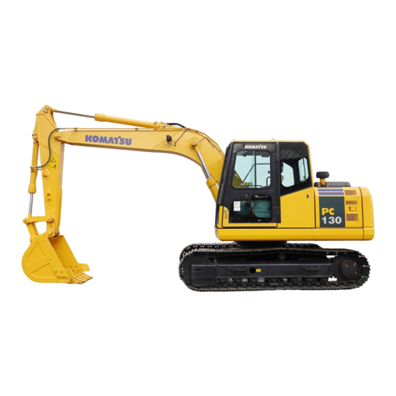
PC130
HYDRAULIC EXCAVATOR
WARNING
Unsafe use of this machine may cause serious injury or
death. Operators and maintenance personnel must read
this manual before operating or maintaining this
machine. This manual should be kept inside the cab for
reference and periodically reviewed by all personel who
will come into contact with the machine.
-7
UEAM003604
Advertisement
Table of Contents

Related Manuals for Komatsu PC130-7


Summary of Contents for Komatsu PC130-7
- Page 1 Operation & UEAM003604 Maintenance Manual PC130 HYDRAULIC EXCAVATOR WARNING Unsafe use of this machine may cause serious injury or death. Operators and maintenance personnel must read this manual before operating or maintaining this machine. This manual should be kept inside the cab for reference and periodically reviewed by all personel who will come into contact with the machine.
- Page 3 FOREWORD...
- Page 4 If you sell the machine, be sure to give this manual to the new owners together with the machine. Komatsu delivers machines that comply with all applicable regulations and standards of the country to which it has been shipped. If this machine has been purchased in another country or purchased from someone in another country, it may lack certain safety devices and specifications that are necessary for use in your country.
-
Page 5: Foreword
FOREWORD SAFETY INFORMATION SAFETY INFORMATION To enable you to use this machine safely, safety precautions and labels are given in this manual and affixed to the machine to give explanations of situations involving potential hazards and of the methods of avoiding such situa- tions. - Page 6 Continuing improvements in the design of this machine can lead to changes in detail which may not be reflected in this manual. Consult Komatsu or your Komatsu distributor for the latest available information of your machine or for questions regarding information in this manual.
-
Page 7: Noise Emission Levels
FOREWORD SAFETY INFORMATION Noise emission levels Two labels indicating the machine noise level are affixed on the machine q Sound pressure level at the operator’s station, measured according to ISO6396 (Dynamic test method, simulated working cycle). q Sound power level emitted by the machine, measured according to ISO 6395 (Dynamic test method, simulated working cycle). -
Page 8: Guide To Reduce Vibration Levels On Machine
FOREWORD SAFETY INFORMATION Guide to Reduce Vibration Levels on Machine The following guides can help an operator of this machine to reduce the whole body vibration levels: 1. Use the correct equipment and attachments. 2. Maintain the machine according to this manual q Tire pressures (for wheeled machines), tension of crawler (for crawler machines) q Brake and steering systems q Controls, hydraulic system and linkages... -
Page 9: Introduction
BREAKING-IN THE NEW MACHINE NOTICE Your Komatsu machine has been thoroughly adjusted and tested before shipment from the factory. How- ever, operating the machine under full load before breaking the machine in can adversely affect the perfor- mance and shorten the machine life. -
Page 10: Product Information
PRODUCT INFORMATION PRODUCT INFORMATION When requesting service or ordering replacement parts, please inform your Komatsu distributor of the following items. PRODUCT IDENTIFICATION NUMBER (PIN)/MACHINE SERIAL NO. PLATE On the bottom right of the operator's cab The design of the nameplate differs according to the territory. -
Page 11: Service Meter Location
SERVICE METER LOCATION On top of the machine monitor YOUR MACHINE SERIAL NUMBERS AND DISTRIBUTOR Machine serial No. Engine serial No. Product Identification Number Manufacturers name: KOMATSU UK Ltd. Address: Durham Road Birtley Chester-Le street County Durham DH32QX United Kingdom... -
Page 12: Machine Serial Number Plate
FOREWORD PRODUCT INFORMATION MACHINE SERIAL NUMBER PLATE Model Seriel Number Manufacturing year Weight Engine power Product Identification Number Manufacturer 1-10... - Page 13 FOREWORD PRODUCT INFORMATION 1-11...
-
Page 14: Table Of Contents
CONTENTS CONTENTS FOREWORD FOREWORD ................................. 1-2 SAFETY INFORMATION............................1-3 NOISE EMISSION LEVELS........................1-5 VIBRATION LEVELS ..........................1-5 GUIDE TO REDUCE VIBRATION LEVELS ON MACHINE .............. 1-6 INTRODUCTION..............................1-7 DIRECTIONS OF MACHINE ........................1-7 BREAKING-IN THE NEW MACHINE ......................1-7 PRODUCT INFORMATION ..........................1-8 PRODUCT IDENTIFICATION NUMBER (PIN)/MACHINE SERIAL NO. - Page 15 CONTENTS CONTROLS AND GAUGES ........................3-3 DETAILED CONTROLS AND GAUGES......................3-4 MONITORING SYSTEM..........................3-4 BASIC CHECK MONITORS ......................3-5 CAUTION MONITORS ........................3-7 EMERGENCY MONITORS ....................... 3-9 METER DISPLAY PORTION......................3-11 MONITOR SWITCHES PORTION ....................3-14 SWITCHES ............................... 3-17 CONTROL LEVERS AND PEDALS ......................3-23 SUN ROOF ...............................
- Page 16 CONTENTS STARTING ENGINE ..........................3-72 NORMAL STARTING ........................3-72 STARTING ENGINE IN COLD WEATHER ..................3-74 AMBIENT TEMPERATURE RANGE FOR OPERATION ................ 6.-76 AFTER STARTING ENGINE ........................3-76 WARMING-UP OPERATION......................3-76 IN COLD WEATHER AREAS ......................3-79 STOPPING THE ENGINE ........................3-83 MACHINE OPERATION ...........................
- Page 17 HANDLING OIL, FUEL, COOLANT, AND PERFORMING OIL CLINIC ............. 4-5 OIL ..............................4-5 FUEL..............................4-5 COOLING SYSTEM COOLANT ......................4-6 GREASE............................4-6 CARRYING OUT KOWA (KOMATSU OIL WEAR ANALYSIS)............4-7 OIL AND FUEL STORAGE........................ 4-8 FILTERS ............................4-8 ELECTRIC SYSTEM MAINTENANCE ....................... 4-8 WEAR PARTS ..............................4-9 WEAR PARTS LIST............................
- Page 18 CONTENTS TIGHTENING TORQUE SPECIFICATIONS ...................... 4-14 TIGHTENING TORQUE LIST ........................4-14 SAFETY CRITICAL PARTS ..........................4-15 SAFETY CRITICAL PARTS LIST ......................4-15 MAINTENANCE SCHEDULE ..........................4-16 MAINTENANCE SCHEDULE CHART ...................... 4-16 MAINTENANCE INTERVAL FOR HYDRAULIC BREAKER..............4-18 MAINTENANCE PROCEDURE.......................... 4-19 INITIAL 250 HOURS MAINTENANCE (ONLY AFTER THE FIRST 250 HOURS) ........
- Page 19 EVERY 5000 HOURS MAINTENANCE....................4-70 CHANGE OIL IN HYDRAULIC TANK..................... 4-70 SPECIFICATIONS SPECIFICATIONS ..............................5-2 EXPLANATION OF LIFTING CAPACITY CHART (PC130-7 1- PC BOOM)..........5-5 EXPLANATION OF LIFTING CAPACITY CHART (PC130-7 2-PC BOOM)..........5-7 ATTACHMENTS AND OPTIONS GENERAL PRECAUTIONS FOR SAFETY......................6-2 HYDRAULIC QUICK COUPLER PIPING ....................
- Page 20 CONTENTS CRUSHER CONTROL FOR ROTATION ....................6-16 ACCUMULATOR ............................6-17 HYDRAULIC SYSTEM - PRESSURE RELEASE................6-17 LONG TERM STORAGE .......................... 6-18 SPECIFICATIONS ............................ 6-18 ATTACHMENT GUIDE ............................6-19 OTHER ATTACHMENTS ......................... 6-19 ATTACHMENT COMBINATIONS......................6-20 TRACK SHOES SELECTION ........................6-21 BUCKET TEETH SELECTION .........................
- Page 21 CONTENTS TRANSPORT & STORAGE OF SUPER LONG FRONT MACHINE ............6-44 INSTALLATION OF SUPPORTING LINK ..................6-44 TRANSPORTATION OF SUPER LONG FRONT MACHINE ..............6-44 WORKING RANGE OF SUPER LONG FRONT..................6-45 LIFTING CAPACITY PC130 SUPER LONG FRONT ................6-46 MAINTENANCE............................
- Page 22 CONTENTS 1-20...
-
Page 23: Safety
SAFETY WARNING Please be sure that you fully understand this manual and the precautions discribed in this manual and the safety labels on the machine. When operating or servicing the machine, always follow these precaustions strictly. -
Page 24: Safety Information
SAFETY SAFETY INFORMATION SAFETY INFORMATION SAFETY LABELS..............................2-42 LOCATION OF SAFETY LABELS ....................... 2-42 SAFETY LABELS............................2-52 SAFETY INFORMATION Safety Rules............................... 2-132 If Abnormalities are Found ......................... 2-132 Working Wear and Personal Protective Items ................... 2-132 Fire Extinguisher and First Aid Kit......................2-132 Safety Equipment............................ - Page 25 SAFETY SAFETY INFORMATION SAFETY MACHINE OPERATION ........................2-232 STARTING ENGINE ..........................2-232 Checks before starting engine ......................2-232 Safety rules for starting engine ......................2-232 Starting engine in cold weather......................2-242 OPERATION............................. 2-252 Checks before operation........................2-252 Safety rules for changing machine directions ................... 2-262 Safety rules for traveling ........................
-
Page 26: Safety Labels
If the labels are damaged, lost, or cannot be read properly, replace them with new ones. For details of the part numbers for the labels, see this manual or the actual label, and place an order with Komatsu distributor. -
Page 27: Safety Labels
SAFETY SAFETY LABELS SAFETY LABELS (1) (207-00-K1951) q Warnings for operation, inspection and maintenance. q Improper operation and maintenance can cause serious injury or death. q Read the manual and labels before operation and maintenance. Follow instructions and warnings in manual and in labels on machine. - Page 28 SAFETY SAFETY LABELS (a) Keep the manual in machine cab near operator. If this manual is lost, please contact your Komatsu distributor for a replacement. (b) Always apply lock when leaving operator's seat. (c) WARNING - No passengers No passengers allowed to ride on machine while it is moving.
- Page 29 SAFETY SAFETY LABELS (d) WARNING - DANGER OF FALLING OBJECTS Do not operate where a danger of falling objects exists. Consult your dealer for fitting of FOPS protections. (e) HAZARDOUS - Voltage hazard Serious injury or death can occur if machine or attachments are not kept safe distance away from electric lines.
- Page 30 SAFETY SAFETY LABELS (2) Precautions when stowing front window (09803-A0481) q When the front window is stowed, there is the hazard that it will fall. q Always lock the front window securely at the stowed posi- tion. (3) Precautions for high-temperature coolant, hydraulic oil (09653-A0481) q Never remove the cap when the engine is at operating (high) temperature.
- Page 31 SAFETY SAFETY LABELS (5) Precautions when adjusting track tension (09657-A0881) q Sign indicates a hazard of flying plug from track adjuster that could cause injury. q Read manual and adjusting track for safe and proper han- dling. (6) Precautions when handling cable (203-00-71130) q Sign indicates an electric hazard from handling the cable.
- Page 32 SAFETY SAFETY LABELS (8) Explanation of method for emergency escape (20Y-00-K2220) EMERGENCY EXIT (9) Caution against falling (09805-A0881) q Sign indicates a hazard of falling off down. q Do not go close to the edge of the machine by mistake. (10) Caution against falling (09805-C0481) q Sign indicates a hazard of falling.
- Page 33 SAFETY SAFETY LABELS (11) Prohibited to enter swing radius (20E-00-K1150) q Sign indicates a chrush hazard by rotation of upper struc- ture of the machine. q Keep away from swinging area of the machine. (12) Precautions for operation (20E-00-K1140) q Sign indicates a hazard of being hit by the working device of the machine.
- Page 34 SAFETY SAFETY LABELS (14) Caution for use of hydraulic quick coupler piping system (20J-00-11271) q There is a danger of an exposed person being killed by fall- ing attachment. q Read the manual for safe operation. 2-12...
-
Page 35: Safety Information
SAFETY SAFETY INFORMATION SAFETY INFORMATION SAFETY RULES q Only trained and authorized personnel can operate and maintain the machine. q Follow all safety rules, precautions and instructions when operating or performing maintenance on the machine. q If you are under the influence of alcohol or medication, your ability to safely operate or repair your machine may be severly impaired putting yourself and everyone else on your jobsite in danger. -
Page 36: Safety Equipment
SAFETY SAFETY INFORMATION SAFETY EQUIPMENT q Be sure that all guards and covers are in their proper position. Have guards and covers repaired immediately if they are damaged. q Understand the method of use of safety features and use them properly. q Never remove any safety features. -
Page 37: Handrails And Steps
SAFETY SAFETY INFORMATION q When leaving the machine, always lower the work equip- ment completely to the ground, set safety lock lever (1) securely to the LOCK position, then stop the engine. Use the key to lock all the equipment. Always remove the key, take it with you, and keep it in the specified place. -
Page 38: Mounting And Dismounting
SAFETY SAFETY INFORMATION MOUNTING AND DISMOUNTING q Never jump on or off the machine. Never get on or off a moving machine. q If the machine starts to move when there is no operator on the machine, do not jump on to the machine and try to stop it. -
Page 39: Fire Prevention And Explosion Prevention
SAFETY SAFETY INFORMATION FIRE PREVENTION AND EXPLOSION PREVENTION q Fire caused by fuel or oil Fuel, oil, antifreeze, and window washer liquid are particu- larly flammable and can be hazardous. To prevent fire, always observe the following: q Do not smoke or use any flame near fuel or oil. q Stop the engine before refueling. -
Page 40: Action If Fire Occurs
Always contact your Komatsu distribu- tor for advice. q Please also refer to Section "ATTACHMENT GUIDE (6- 19)"... -
Page 41: Attachment Installation
No attempt should be made to repair these parts as this may have an adverse effect on component strength or durability. If such a repair is undertaken without authorisation from Komatsu there is a danger that a problem might occur that will lead to serious personal injury. -
Page 42: Working On Loose Ground
SAFETY SAFETY INFORMATION q If water lines, gas lines, or high-voltage electrical lines may be buried under the worksite, contact each utility and iden- tify their locations. Be careful not to sever or damage any of these lines. q Take action to prevent unauthorized people from approach- ing the jobsite. -
Page 43: Ensure Good Visibility
SAFETY SAFETY INFORMATION ENSURE GOOD VISIBILITY This machine is equipped with mirrors to improve the visibility, but even with mirrors, there are places, which can- not be seen from the operators seat, so always be careful when operating. When operating or travelling in places with poor visibility, if it is impossible to confirm the condition of the job site or obstacle is in the area around the machine, there is danger that the machine may suffer damage or the operator may suffer serious personal injury. - Page 44 Do not allow other persons to approach during the operation. q Always observe the rules and regulations for the work site and environmental standards. This machine does not use asbestos, but there is a danger that imitation parts may contain asbestos, so always use genuine Komatsu parts. 2-22...
-
Page 45: Safety Machine Operation
SAFETY SAFETY MACHINE OPERATION SAFETY MACHINE OPERATION STARTING ENGINE If there is a warning tag hanging from the work equipment con- trol lever, do not start the engine or touch the levers . CHECKS BEFORE STARTING ENGINE Carry out the following checks before starting the engine at the beginning of the day's work. q Remove all dirt from the surface of the window glass to ensure a good view. - Page 46 SAFETY SAFETY MACHINE OPERATION q Do not allow anyone apart from the operator to ride on the machine. STARTING ENGINE IN COLD WEATHER q Carry out the warming-up operation thoroughly. If the machine is not thoroughly warmed up before the control levers are operated, the reaction of the machine will be slow, and this may lead to unexpected accidents.
-
Page 47: Operation
SAFETY SAFETY MACHINE OPERATION OPERATION CHECKS BEFORE OPERATION When carrying out the checks, move the machine to a wide area where there are no obstructions, and operate slowly. Do not allow anyone near the machine. q Always fasten your seat belt. q Check that the movement of the machine matches the display on the control pattern card. - Page 48 SAFETY SAFETY MACHINE OPERATION SAFETY RULES FOR CHANGING MACHINE DIRECTIONS q Before traveling, position the upper structure so that the sprocket (1) is at the rear of the operator's cab. If the sprocket (1) is at the front of the operator's cab, the machine makes a movement reverse to the control lever movement (for example, forward becomes reverse, and left becomes right).
- Page 49 SAFETY SAFETY MACHINE OPERATION SAFETY RULES FOR TRAVELING q When traveling on flat ground, keep the work equipment 40 to 50 cm high above the ground. q If the work equipment blocks the view and it is difficult to travel in safety, raise the work equipment to a greater height.
- Page 50 SAFETY SAFETY MACHINE OPERATION TRAVELING ON SLOPES To prevent the machine from tipping over or slipping to the side, always do as follows. q Keep the work equipment approx. 20 to 30 cm above the ground. In case of emergency, lower the work equipment to the ground immediately to help stop the machine.
- Page 51 SAFETY SAFETY MACHINE OPERATION OPERATIONS ON SLOPES q When working on slopes, there is a hazard that the machine may lose its balance and turn over when the swing or work equipment are operated. This may lead to serious injury or property damage, so always provide a stable place when carrying out these operations, and operate carefully.
- Page 52 SAFETY SAFETY MACHINE OPERATION q Do not carry out demolition work under the machine. There is a hazard that the machine may become unstable and tip over. q When working on or from the top of buildings or other structures, check the strength and the structure before starting operations.
- Page 53 SAFETY SAFETY MACHINE OPERATION OPERATIONS ON SNOW q Snow-covered or frozen surfaces are slippery, so be extremely careful when traveling or operating the machine, and do not operate the levers suddenly. Even a slight slope may cause the machine to slip, so be particularly careful when working on slopes.
-
Page 54: Transportation
SAFETY MACHINE OPERATION TRANSPORTATION The machine can be divided into parts for transportation, so when transportating the machine, please contact your Komatsu distributor to have the work carried out. LOADING AND UNLOADING When loading or unloading the machine, mistaken operation may bring the hazard of the machine tipping over or falling, so particular care is necessary. -
Page 55: Battery
SAFETY SAFETY MACHINE OPERATION BATTERY BATTERY HAZARD PREVENTION Battery electrolyte contains sulphuric acid, and batteries generate flammable hydrogen gas, which may explode. Mistaken handling can lead to serious injury or fire. For this reason, always observe the following precautions. q Do not use or charge the battery if the battery electrolyte level is below the LOWER LEVEL line. This may cause an explosion. - Page 56 SAFETY SAFETY MACHINE OPERATION STARTING ENGINE WITH BOOSTER CABLES If any mistake is made in the method of connecting the booster cables, it may cause the battery to explode, so always do as follows. q When starting with a booster cable, carry out the starting operation with two workers (one worker sitting in the opera- tor's seat and the other working with the battery).
-
Page 57: Towing
SAFETY SAFETY MACHINE OPERATION TOWING SAFETY RULES FOR TOWING Serious injury or death could result if a disabled machine is towed incorrectly or if there is a mistake in the selec- tion or inspection of the wire rope. For towing, see “TOWING THE MACHINE (3-123)“. q Always wear leather gloves when handling wire rope. -
Page 58: Lifting Objects With Bucket
SAFETY SAFETY MACHINE OPERATION LIFTING OBJECTS WITH BUCKET As a basic rule it is prohibited to carry out operations lifting objects with this standard specification machine. LIFTING WORK USING BUCKET WITH HOOK As a basic rule, it is prohibited to carry out lifting operations. However, if the work fulfils the specified conditions and only if it fulfils the specified conditions, it is permitted to carry out lifting operations using a bucket with a hook. - Page 59 SAFETY SAFETY MACHINE OPERATION q Do not use the work equipment or swing to pull the load in any direction. There is danger that the hook may break and the load come off, causing the work equipment to move suddenly and cause personal injury. 2-37...
-
Page 60: Safety Maintenance Information
SAFETY SAFETY MAINTENANCE INFORMATION SAFETY MAINTENANCE INFORMATION WARNING TAG q Always attach the “DO NOT OPERATE“ warning tag to the work equipment control lever in the operator's cab to alert others that you are performing service or maintenance on the machine. Attach additional warning tags around the machine if nec- essary. - Page 61 SAFETY SAFETY MAINTENANCE INFORMATION STOP ENGINE BEFORE CARRYING OUT MAINTENANCE q Stop the machine on firm, level ground. q Select a place where there is no hazard of falling rocks or landslides, or of flooding if the land is low. q Lower the work equipment completely to the ground and stop the engine.
- Page 62 Do not hit or roll the accumulator, or subject it to any impact. q When disposing of the accumulator, the gas must be released. Please contact your Komatsu distributor to have this work performed. PERSONNEL Only authorized personnel can service and repair the machine. Do not allow unauthorized personnel into the area.
- Page 63 SAFETY SAFETY MAINTENANCE INFORMATION ATTACHMENTS q Appoint a leader before starting removal or installation operations for attachments. q Place attachments that have been removed from the machine in a stable condition so that they do not fall. And take steps to prevent unauthorized persons from entering the storage area.
- Page 64 Never attempt to disassemble the recoils spring assembly. It contains a spring under high pressure which serves as a shock absorber for the idler. If it is disassembled by mistake, the spring will fly out and cause serious injury. When it becomes necessary to disassemble it, ask your Komatsu distributor to do the work. 2-42...
- Page 65 If any loose bolts are found, stop work and tighten to the specified torque. If any damaged hoses are found, stop operations immediately and contact your Komatsu distributor. Replace the hose if any of the following problems are found.
- Page 66 SAFETY SAFETY MAINTENANCE INFORMATION AIR CONDITIONER MAINTENANCE If air conditioner refrigerant gets into your eyes, it may cause blindness; if it touches your skin, it may cause frost- bite. Never touch refrigerant. COMPRESSED AIR q When carrying out cleaning with compressed air, there is a hazard of serious injury caused by flying particles. q When using compressed air to clean elements or the radiator, always wear safety goggles, dust mask, gloves, and other protective equipment.
-
Page 67: Operation
OPERATION WARNING Please read and make sure that you understand the safety volume before reading this section. -
Page 68: Machine View Illustrations
OPERATION MACHINE VIEW ILLUSTRATIONS MACHINE VIEW ILLUSTRATIONS OVERALL MACHINE VIEW Bucket Boom cylinder Bucket cylinder Sprocket Track frame Arm cylinder Track shoe Boom (10) Idler... -
Page 69: Controls And Gauges
OPERATION MACHINE VIEW ILLUSTRATIONS CONTROLS AND GAUGES Heated operator seat switch (if equipped) (20) Pump drive Emergency switch Rotating lamp switch (if equipped) (21) Travel speed selector switch Lower wiper switch (if equipped) (22) Auto-deceleration switch Air conditioner control switch (23) Charge level monitor Safety lock lever... -
Page 70: Detailed Controls And Gauges
OPERATION DETAILED CONTROLS AND GAUGES DETAILED CONTROLS AND GAUGES The following is an explanation of the devices needed for operating the machine. To perform suitable operations correctly and safely, it is important to completely understand the methods of operat- ing equipment and meanings of the displays. MONITORING SYSTEM Basic check monitors Meter Display Portion... -
Page 71: Basic Check Monitors
OPERATION DETAILED CONTROLS AND GAUGES Basic Check Monitors CAUTION These monitors DO NOT ensure that the machine is in good condition. When performing checks before starting (daily checks), do not simply rely on the monitors. Always dismount the machine and check each item directly. - Page 72 If the set time (125, 250, 500 H) passes after the engine oil is replaced, this lamp lights up. If the lamp lights up, change the engine oil. When you want to change the oil replacement interval, consult Komatsu Ltd. or its distributor.
-
Page 73: Caution Monitors
OPERATION DETAILED CONTROLS AND GAUGES Caution Monitors CAUTION If the warning monitor flashes, check the problem point as soon as possible and carry out maintenance. Failure to repair the problem will lead to failure of the machine. These are items which need to be observed while the engine is running. If any abnormality occurs, items which need to be repaired as soon as possible are displayed. - Page 74 OPERATION DETAILED CONTROLS AND GAUGES Charge Level Monitor This monitor (1) flashes if the battery is not being properly charged when the engine is running. If it flashes, check the V-belt for looseness. If any abnormality is found, take the action given in “OTHER TROUBLE (3-129)“. REMARK When the starting switch is at ON, the lamp stays lighted up.
-
Page 75: Emergency Monitors
OPERATION DETAILED CONTROLS AND GAUGES Emergency Monitors CAUTION If the monitor lights up red, stop the engine immediately or run at low idle, check applicable location, then perform necessary actions. These items should be observed while the engine is running. If there is an abnormality, monitor for the abnormal location lights up red and buzzer sounds, so perform action immediately. - Page 76 OPERATION DETAILED CONTROLS AND GAUGES Engine Oil Pressure Monitor If the engine lubricating pressure is below the normal value, this monitor (2) flashes. If it flashes, stop the engine, and check the oil level in the oil pan and lubricating system. REMARK When the starting switch is ON, the lamp is always lighted up.
-
Page 77: Meter Display Portion
OPERATION DETAILED CONTROLS AND GAUGES Meter Display Portion D (1) Engine pre-heating monitor D (4) Fuel gauge D (2) Swing lock monitor D (5) Service meter D (3) Engine coolant temperature gauge D (6) Display Pilot Display When ignition switch is ON, the pilot display lights up when display items are functioning. Engine Pre-heating Monitor This monitor (1) indicates the pre-heating time required when starting the engine at an ambient temperature below 0°C. - Page 78 OPERATION DETAILED CONTROLS AND GAUGES Swing Lock Monitor This monitor (2) informs the operator that the swing lock is being actuated. Actuated: Lights up When the swing lock switch is turned ON (ACTUATED), the monitor lamp lights up. When the swing holding brake relase switch is turned on, this monitor lamp flashes.
- Page 79 OPERATION DETAILED CONTROLS AND GAUGES Fuel Gauge This meter (4) shows the amount of fuel in the fuel tank. The green range should light up during operations. If only the red range lights up during operations, there is less than 46 liters of fuel remaining, so check and add fuel. Red range (A) lights up: Fuel gauge monitor lamp (B) flashes.
-
Page 80: Monitor Switches Portion
If it is desired to have the working mode set to start automatically in E, L, or B mode (default options setting), please ask your Komatsu distributor to change the setting. NOTICE Do not use A mode when using a breaker. Otherwise the breaker will likely be damaged. - Page 81 OPERATION DETAILED CONTROLS AND GAUGES Auto-deceleration Switch (Selection Switch) This switch (2) acts to activate the function that automatically lowers the engine speed and reduces fuel consumption when the control levers are at neutral. Auto-deceleration lights up: Auto-deceleration is actuated Auto-deceleration goes out: Auto-deceleration is canceled Each time the switch is pressed, the auto-deceleration is actu- ated or canceled.
- Page 82 OPERATION DETAILED CONTROLS AND GAUGES Window Washer Switch This switch (5) is kept continuously pressed, window washer fluid is sprayed out on the front glass. When the switch is released, the spray stops. q If switch (5) is kept pressed when the wiper is stopped, the window washer fluid will spray out, and at the same time, the wiper will be actuated continuously.
-
Page 83: Switches
OPERATION DETAILED CONTROLS AND GAUGES SWITCHES Starting switch Knob switch Fuel control dial Room lamp switch Cigarette lighter (10) Pump drive Emergency switch Swing lock switch (11) Swing holding brake release switch Lamp switch (12) Rotating lamp switch (if equipped) Alarm buzzer stop switch (13) Heated operator seat switch (if equipped) - Page 84 OPERATION DETAILED CONTROLS AND GAUGES (D): HEAT position Set to this position when starting the engine in cold weather. When the key is set to HEAT position (D), the preheating monitor lights up. Keep the key at the HEAT position until the preheating monitor flashes.
- Page 85 OPERATION DETAILED CONTROLS AND GAUGES Swing Lock Switch WARNING q When not using the swing operation, e.g. in traveling, put the swing lock switch to the OFF position. q On slopes, even when the swing lock switch is at the ON position, the weight of the work equipment may cause the upper structure to swing if the swing control lever is operated in the downhill direction.
- Page 86 OPERATION DETAILED CONTROLS AND GAUGES Horn Switch When the button (7) at the tip of the right work equipment con- trol lever is pressed, the horn will sound. Knob Switch Use knob switch (8) on the left work equipment control lever to activate the one-touch power max./slow-down function.
- Page 87 OPERATION DETAILED CONTROLS AND GAUGES Pump Drive Emergency Switch NOTICE The emergency pump driving switch is provided to make it possible to carry out work for a short time when there is a failure in pump control system. It is necessary to repair the abnormal location as soon as possible.
- Page 88 OPERATION DETAILED CONTROLS AND GAUGES Heated operator seat switch (if equipped) This switch (13) is used to switch on the heted seat. (a) ON: seat heated (b) OFF: seat not heated Lower Wiper Switch (if equipped) This switch (14) activates the front lower wiper. (a) ON: wiper moves continuously (b) OFF: wiper stops NB.
-
Page 89: Control Levers And Pedals
OPERATION DETAILED CONTROLS AND GAUGES CONTROL LEVERS AND PEDALS Safety lock lever Left work equipment control lever (with auto-deceleration system) Travel levers Right work equipment control lever (with a pedal and auto-deceleration system) (with auto-deceleration system) Safety Lock Lever WARNING q When leaving the operator's compartment, set the safety lock lever (1) securely to the LOCK position (L). - Page 90 OPERATION DETAILED CONTROLS AND GAUGES Travel Levers WARNING q Do not rest your foot on the pedal during operations. If the pedal is depressed by mistake, the machine may suddenly move and cause a serious accident. Be extremely careful when operating the pedal for travel or steering operations.
- Page 91 OPERATION DETAILED CONTROLS AND GAUGES Work Equipment Control Lever This Left work equipment control lever (3) is used to operate the arm and upper structure. Arm operation (a) Arm OUT (b) Arm IN Swing operation (c) Swing to right (d) Swing to left N (Neutral) : The upper structure and arm are held in position and do not move.
-
Page 92: Sun Roof
OPERATION DETAILED CONTROLS AND GAUGES SUN ROOF WARNING When leaving the operator's seat, set the safety lock lever securely to the LOCK position (L). If the safety lock lever (1) is at the FREE position (F) and the control lever is touched by mistake, this may lead to a serious accident. - Page 93 OPERATION DETAILED CONTROLS AND GAUGES Opening 1. Stop the machine on level ground, lower the work equip- ment completely to the ground, then stop the engine. 2. Set the safety lock lever securely to the LOCK position (L). 3. Check that the wiper blade is stowed in the right stay. 4.
- Page 94 OPERATION DETAILED CONTROLS AND GAUGES 5. Hold lower knob (C) with your left hand from inside the operator's cab, and with your right hand, grip top knob (D), pull it up, and push it against lock catch (E) at the rear of the cab securely to lock the window.
- Page 95 OPERATION DETAILED CONTROLS AND GAUGES Closing WARNING When closing the window, lower it slowly and be careful not to get your hand caught. 1. Stop the machine on level ground, lower the work equipment completely to the ground, then stop the engine. 2.
- Page 96 OPERATION DETAILED CONTROLS AND GAUGES 5. When the bottom of the window reaches the top of the bot- tom window, push the top of the window to the front to push it against left and right lock catches (G) and engage the lock.
-
Page 97: Emergency Exit From Operator's Cab
OPERATION DETAILED CONTROLS AND GAUGES EMERGENCY EXIT FROM OPERATOR'S CAB q If for some reason, the cab door does not open, remove the rear window and use it as an emergency escape. q Remove the rear window as follows. 1. Pull ring (1) and completely remove seal (2) from the rub- ber core. -
Page 98: Cap With Lock
OPERATION DETAILED CONTROLS AND GAUGES CAP WITH LOCK Use the starting key to open and close the locks on the caps and covers. For details of the locations of the caps and covers with locks, see “LOCKING (3-106)“. Insert the key as far as it will go to the shoulder. If the key is turned before it is inserted all the way, it may break. - Page 99 OPERATION DETAILED CONTROLS AND GAUGES Opening and Closing Cover with Lock Opening the Cover (Locked Cover) 1. Insert the key into the key slot. 2. Turn the key counterclockwise and open the cover by pull- ing the cover grip. (A): Open (B): Lock Locking the Cover 1.
-
Page 100: Hot And Cool Box
OPERATION DETAILED CONTROLS AND GAUGES HOT AND COOL BOX This is on the right side at the rear of the operator's seat. It is interconnected with the air conditioner: it stays warm when the heating is used, and stays cool when the cooling is used. MAGAZINE BOX (The cup holder is provided separately at the front of the magazine box.) This is on the left side of the operator's seat. -
Page 101: Air Conditioner Controls
OPERATION DETAILED CONTROLS AND GAUGES AIR CONDITIONER CONTROLS Air Conditioner Control Panel OFF switch FRESH/RECIRC selector switch Fan switch Display monitor Temperature control switch Air conditioner switch Vent selector switch Sunlight sensor Auto switch OFF Switch Switch (1) is used to stop the fan and air conditioner. q When OFF switch (1) is pressed, the set temperature and air flow displayed on monitor (7), the lamps above auto switch (5), and air conditioner (8) go out, and operation... - Page 102 OPERATION DETAILED CONTROLS AND GAUGES Fan Switch This switch (2) is used to adjust the air flow. The air flow can be adjusted to six levels. q Press the ∧ switch to increase the air flow; press the ∨ switch to reduce the air flow. q During auto operation, the air flow is automatically adjusted.
- Page 103 OPERATION DETAILED CONTROLS AND GAUGES REMARK If the mode is set to auto mode and the temperature setting is set to 18.0 °C and 32.0 °C, the air flow from the fan is always set to HIGH and does not change even when the set temperature is reached. Vent Selector Switch This switch (4) is used to select the vents.
- Page 104 OPERATION DETAILED CONTROLS AND GAUGES Auto Switch With this switch (5), the air flow, vents, and air source (RECIRC/FRESH) are automatically selected according to the set temperature. q When auto switch (5) is pressed, the lamp at the top of the auto switch lights up.
- Page 105 OPERATION DETAILED CONTROLS AND GAUGES Air Conditioner Switch This switch (8) is used to turn the air conditioner (cooling, dehumidifying, heating) ON or OFF. q When the fan is acutated (the display monitor shows (b)) and air conditioner switch (8) is pressed, the air conditioner is switched ON, the lamp at the top of the air conditioner switch lights up, and the air conditioner starts.
-
Page 106: Method Of Operation
OPERATION DETAILED CONTROLS AND GAUGES Method of Operation The air conditioner can be operated automatically or manually. Select the method of operation as desired. Automatic Operation 1. Turn auto switch (5) ON. q The lamp at the top of switch (5) lights up. q The set temperature (a) and air flow (b) are displayed on the monitor. - Page 107 OPERATION DETAILED CONTROLS AND GAUGES Stopping Automatic Operation Press OFF switch (1). The displays for temperature setting (a) and air flow (b) on monitor (7), and lamps above auto switch (5) and air conditioner switch (8) go out, the operation stops. Manual Operation 1.
- Page 108 OPERATION DETAILED CONTROLS AND GAUGES 3. Press temperature setting switch (3) and adjust tempera- ture inside the cab. 4. Press vent selector switch (4) and select the desired vents. When this is done, the display for vent (c) of the display monitor changes according to the selection.
- Page 109 OPERATION DETAILED CONTROLS AND GAUGES Stopping Manual Operation Press OFF switch (1). The displays for temperature setting (a) and air flow (b) on monitor (7), and lamps above auto switch (5) and air conditioner switch (8) go out, the operation stops. Operation with Cold Air to Face and Warm Air to Feet To operate with cold air blowing to the face and warm air blow- ing to the feet, set as follows.
- Page 110 OPERATION DETAILED CONTROLS AND GAUGES 3. Turn air conditioner switch (8) ON. Check that the lamp at the top of the air conditioner switch lights up. 4. Adjust fan switch (2), temperature setting switch (3) and FRESH/RECIRC selector switch (6) to the desired posi- tions.
- Page 111 OPERATION DETAILED CONTROLS AND GAUGES 2. Press vent selector switch (4) and set the vent display on the display monitor (C) to the display shown in (f) or (g) in the diagram on the right. 3. Press FRESH/RECIRC selector switch (6) and set it to take in fresh air.
-
Page 112: Use Air Conditioner With Care
OPERATION DETAILED CONTROLS AND GAUGES When operating in the rainy season or when it is desired to remove the mist from the window glass or to dehumidify the air, turn air conditioner switch (8) ON. Use Air Conditioner with Care NOTICE q When running the air conditioner, always start with the engine running at low speed. -
Page 113: Other Functions
After completing the troubleshooting, press OFF switch (1) again to return to the normal display. If any abnormality is detected by the self-diagnostic function, ask your Komatsu distributor to carry out inspection and repair. -
Page 114: Cab Radio Cassette
OPERATION DETAILED CONTROLS AND GAUGES Function to Switch Set Temperature Display Between Fahrenheit and Celsius It is possible to switch the set temperature display between °F and °C. ∨ ∧ If the “ “ and “ “ portions of temperature setting switch (3) are pressed at the same time for more than 5 seconds while the fan is running, the temperature display will switch between °F and °C. -
Page 115: Auxiliary Electric Power
OPERATION DETAILED CONTROLS AND GAUGES AUXILIARY ELECTRIC POWER 24V power source NOTICE Do not use this as the power source for 12 V equipment. Pull out the connector plug for taking out electric power from the rear side of the panel. Maximum usable electric power is 85 W (24 V x 3.5 A). -
Page 116: Fuse
OPERATION DETAILED CONTROLS AND GAUGES FUSE NOTICE Before replacing a fuse, be sure to turn off the starting switch. The fuses protect the electrical equipment and wiring from burning out. If the fuse becomes corroded, or white powder can be seen, or the fuse is loose in the fuse holder, replace the fuse. -
Page 117: Fusible Link
Be careful not to get water, mud, or juice on the con- troller. This will cause failure. q If any abnormality occurs in the controller, do not dis- assemble it yourself. Contact your Komatsu distribu- tor for repairs. TOOL BOX This is used for keeping the tools. -
Page 118: Handling Grease Gun
DETAILED CONTROLS AND GAUGES HANDLING GREASE GUN When using the Komatsu genuine greasing gun, follow the procedure given below. 1. Pull chain (3) and lock it in the groove of grease cylinder (1). 2. Twist grease cylinder (1) back and remove it from body (2). -
Page 119: Refuelling Pump
OPERATION DETAILED CONTROLS AND GAUGES REFUELLING PUMP Safety q Do not bring fire or sparks near fuel - smoking is prohibited. q In event of ingested fuel - do not induce vomiting. Drink large quantity of milk or water and seek medical atten- tion. - Page 120 OPERATION DETAILED CONTROLS AND GAUGES REMARK The pump is protected by a fuse. If pump fails to function, check fuse (10A). Do not allow the pump to run dry, as this will overheat the motor. If the barrel is empited during the refuelling stop the pump immediatly.
-
Page 121: Accumulator
Do not make holes in it or weld it. Do not hit it, roll it, or subject it to any impact. When disposing of the accumulator, the gas must be released. Please contact your Komatsu distributor to have this work carried out. -
Page 122: Machine Operations And Controls
Leakage of fuel or oil will cause the machine to catch fire. Check carefully, and be sure to repair any abnormalities, or please contact your Komatsu distributor. Carry out the following inspections and cleaning every day before starting the engine for the day's work. - Page 123 Check that there is no abnormality in the seat belt or mounting clamps. If there is any damage, replace with new parts. 10. Check bucket with hook (if equipped) for damage. Check that there is no damage to the hook, guide, or hook mount. If any abnormality is found, please contact your Komatsu distributor for repair. 3-57...
-
Page 124: Checks Before Starting
OPERATION MACHINE OPERATIONS AND CONTROLS Checks Before Starting Always check the items in this section before starting the engine each day. Check Coolant Level, Add Coolant WARNING q Do not open the radiator cap unless necessary. When checking the coolant, always wait for the engine to cool down and check the sub tank. - Page 125 OPERATION MACHINE OPERATIONS AND CONTROLS Check Oil Level in Engine Oil Pan, Add Oil WARNING Engine parts and oil are at high temperature immediately after the engine is stopped, and will cause seri- ous burns. Wait for the temperature to cool down before starting the operation. 1.
- Page 126 OPERATION MACHINE OPERATIONS AND CONTROLS Check Fuel Level, Add Fuel WARNING When adding fuel, never let the fuel overflow. This may cause a fire. If any fuel is spilled, wipe it up com- pletely. Never bring flames near fuel because it is highly flammable and dangerous. 1.
- Page 127 OPERATION MACHINE OPERATIONS AND CONTROLS Drain Water And Sediment from Fuel Tank 1. Set a container under the drain valve (1) to catch the fuel when it is drained. 2. Open drain valve (1) at the rear of the fuel tank and drain the water and sediment accumulated at the bottom of the tank.
- Page 128 Turn the lamp switch to the ON position and check that the working lamp light up. If the lamps do not light up, there is probably a broken bulb or disconnection in the wiring, so contact your Komatsu distributor for repairs. 3-62...
- Page 129 Check Function of Horn 1. Turn the starting switch to the ON position. 2. Confirm that the horn sounds immediately when the horn button is pressed. If the horn does not sound, please contact your Komatsu distributor for repair. 3-63...
-
Page 130: Adjustment
OPERATION MACHINE OPERATIONS AND CONTROLS Adjustment Seat Adjustment WARNING When adjusting the position of the operator's seat, always set the safety lock lever to the LOCK position to prevent any accidental contact with the control levers. q Always adjust the operator's seat before starting each operation or when the operators change shift. q Adjust the seat so that the control levers and switchis can be operated freely and easily with the operator back against the backrest. - Page 131 OPERATION MACHINE OPERATIONS AND CONTROLS Pull lever (4) up to adjust the angle of the rear of the seat. (4 stages) q To raise the angle at the rear of the seat,keep the lever (3) pulled up and stand up slightly to remove your weight from the seat.
- Page 132 OPERATION MACHINE OPERATIONS AND CONTROLS Rearview Mirrors WARNING Be sure to adjust the mirrors before starting work. If they are not adjusted properly, you cannot secure the visibility and may be injured or may injure someone seriously. Mirror (A) Adjust the mirror mount so that it is possible to see people at the rear left of the machine.
- Page 133 OPERATION MACHINE OPERATIONS AND CONTROLS Mirror (B) Adjust thhe mirror mount so that it is possiblle to see people at the rear right of the machine. q Install the view mirror in the location indicated in the figure at the right. (M): 170mm q If the side view mirror does not move smoothly when adjusting is angle, loosen mirror securing bolt (3) and mir-...
- Page 134 OPERATION MACHINE OPERATIONS AND CONTROLS q If side view mirror (D) does not move smoothly when adjusting its angle, loosen mirror securing screw (6). Tightening torque of screw (6): 0.98-1.47Nm (0.10-0.15 kgf-m) q Install the side view mirror (E) in the location indicated in the figure at right.
-
Page 135: Seat Belt
OPERATION MACHINE OPERATIONS AND CONTROLS Seat Belt WARNING q Before fitting the seat belt, check that there is no abnormality in the belt mount bracket or mounting belt. If it is worn or damaged, replace the seat belt. q Even if no abnormality can be seen in the belt, replace the seat belt every 3 years. The date of manu- facture of the belt is shown on the back of the belt. -
Page 136: Operations Before Starting Engine
OPERATION MACHINE OPERATIONS AND CONTROLS Operations Before Starting Engine WARNING When starting the engine, check that the safety lock lever is securely at the LOCK position (L). If the control levers are not locked and they are touched by accident when starting the engine, the work equipment may move unexpectedly, and this may lead to a serious accident. - Page 137 If the monitors or gauges do not light up or the buzzer does not sound, there is probably a blown bulb or discon- nection, so please contact your Komatsu distributor for repair. After approx. 3 seconds, the following monitors and gauges will stay lighted up; the other monitors and gauges will go out.
-
Page 138: Starting Engine
OPERATION MACHINE OPERATIONS AND CONTROLS STARTING ENGINE Normal Starting WARNING q Start the engine only after sitting down in the opera- tor's seat. q Do not attempt to start the engine by short-circuiting the engine starting circuit. Such an act may cause seri- ous bodily injury or fire. - Page 139 OPERATION MACHINE OPERATIONS AND CONTROLS 3. Turn the key in starting switch (3) to the START position (C). The engine will start. 4. After the engine starts, release the key in starting switch (3). The key will automatically return to the ON position (B). 5.
-
Page 140: Starting Engine In Cold Weather
OPERATION MACHINE OPERATIONS AND CONTROLS Starting Engine in Cold Weather WARNING q Start the engine only after sitting down in the operator's seat. q Do not attempt to start the engine by short-circuiting the engine starting circuit. Such an act may cause a serious bodily injury or fire. - Page 141 OPERATION MACHINE OPERATIONS AND CONTROLS 3. Hold the key in starting switch (3) at the HEAT position (D), and check that preheating monitor (4) lights up. After about 30 seconds, preheating monitor lamp (4) will flash to indi- cate that preheating is finished. (The flashing will stop after approx.
-
Page 142: Ambient Temperature Range For Operation
OPERATION MACHINE OPERATIONS AND CONTROLS AMBIENT TEMPERATURE RANGE FOR OPERATION q The recommended ambient temperature range for operation is -20 C to +45 q When operating in ambients below 0 C, refer to "COLD WEATHER OPERATION (3-117)" for detail of precau- tions. - Page 143 OPERATION MACHINE OPERATIONS AND CONTROLS After starting the engine, do not immediately start operations. First, carry out the following operations and checks. 1. Turn fuel control dial (2) to center position (a) between the low idling (MIN) and high idling (MAX) positions and run the engine at a mid-range speed under no load until the engine water temperature monitor gives a green display.
- Page 144 Engine pre-heating monitor (15): Is it lighted up? 6. Check that there is no abnormal exhaust gas color, noise or vibration. If any abnormality is found, contact your Komatsu distributor. 7. If air cleaner clogging monitor (13) is lighted up, clean or replace the element immediately.
-
Page 145: In Cold Weather Areas
OPERATION MACHINE OPERATIONS AND CONTROLS In Cold Weather Areas (AUTOMATIC WARMING-UP OPERATION) This machine is equipped with an automatic warming-up device. When the engine is started, if the engine water temperature is low (below 30 °C), the warming-up operation is car- ried out automatically. - Page 146 OPERATION MACHINE OPERATIONS AND CONTROLS 4. Set safety lock lever (1) to the FREE position (F) and raise the bucket from the ground. 5. Operate bucket control lever (3) and arm control lever (4) slowly to move the bucket cylinder and arm cylinder to the end of the stroke.
- Page 147 Engine pre-heating monitor (15): Is it lighted up? 8. Check that there is no abnormal exhaust gas color, noise or vibration. If any abnormality is found, contact your Komatsu distributor. 9. If air cleaner clogging monitor (13) is lighted up, clean or replace the element immediately.
- Page 148 OPERATION MACHINE OPERATIONS AND CONTROLS 12. Use the working mode switch on monitor panel (16) to select the working mode to be used. NOTICE Canceling automatic warming-up operation If it becomes necessary in an emergency to cancel the automatic warming-up operation or to lower the engine speed to low idling, do as follows.
-
Page 149: Stopping The Engine
OPERATION MACHINE OPERATIONS AND CONTROLS STOPPING THE ENGINE NOTICE If the engine is stopped abruptly, service life of component parts of the engine may be considerably reduced. Hence do not stop the engine abruptly except in an emergency. If the engine has overheated, do not try to stop it abruptly but run it at medium speed to allow it to cool down gradu- ally, and then stop it. -
Page 150: Machine Operation
OPERATION MACHINE OPERATIONS AND CONTROLS MACHINE OPERATION Preparations for Moving the Machine Off WARNING q Before operating the steering levers, check the direc- tion of the track frame. If the sprocket is at the front, the operation of the travel levers is reversed. -
Page 151: Moving Machine Forward
(6) slowly to move the machine off. 3. For machines equipped with a travel alarm, check that the alarm sounds. If the alarm does not sound, please contact your Komatsu distributor for repair. REMARK In cold temperatures, if the machine travel speed is not normal, carry out the warming-up operation thoroughly. -
Page 152: Moving Machine Backward
Push levers (5) forward slowly or depress the front part of pedals (6) to move the machine off. 3. For machines equipped with a travel alarm, check that the alarm sounds. If the alarm does not sound, please contact your Komatsu distributor for repair. 3-86... -
Page 153: Stopping Machine
OPERATION MACHINE OPERATIONS AND CONTROLS Stopping Machine Avoid stopping suddenly. Give yourself ample room when stopping. 1. Put the left and right travel levers (1) in the neutral position, then stop the machine. 3-87... -
Page 154: Steering The Machine
OPERATION MACHINE OPERATIONS AND CONTROLS STEERING THE MACHINE Steering WARNING Before operating the travel levers, check the direction of the track frame (the position of the sprocket). If the sprocket is at the rear, the machine moves in the reverse direction to the operation of the travel levers. Use the travel levers to change direction. - Page 155 OPERATION MACHINE OPERATIONS AND CONTROLS Changing Direction of the Machine When turning to the left: If the left travel lever is returned to the neutral position, the machine will turn to the left. (A): Forward left turn (B): Reverse left turn REMARK When turning to the right, operate the right travel lever in the same way.
-
Page 156: Swinging
OPERATION MACHINE OPERATIONS AND CONTROLS SWINGING WARNING The tail of the machine extends outside the tracks. Before operating the swing, check that the area around the machine is safe. 1. Before starting the swing operation, turn swing lock switch (1) OFF and check that swing lock monitor (2) has gone out. -
Page 157: Work Equipment Controls And Operations
OPERATION MACHINE OPERATIONS AND CONTROLS WORK EQUIPMENT CONTROLS AND OPERATIONS WARNING If the lever is operated when the engine speed has been lowered by the auto-deceleration function, the engine speed will suddenly rise, so operate the levers carefully. Use the control levers to operate the work equipment. Note that when the levers are released, they return to the HOLD position and the work equipment is held in that position. - Page 158 OPERATION MACHINE OPERATIONS AND CONTROLS Boom operation Bucket operation 3-92...
-
Page 159: Working Mode
OPERATION MACHINE OPERATIONS AND CONTROLS WORKING MODE Working Mode The mode selector switch can be used to switch the mode to match the operating conditions and purpose, thereby enabling work to be carried out efficiently. Make effective use of each mode as follows. When the starting switch is turned ON, the working mode is set to A mode (digging). -
Page 160: Prohibited Operations
OPERATION MACHINE OPERATIONS AND CONTROLS PROHIBITED OPERATIONS WARNING q If it is necessary to operate the work equipment control lever when the machine is traveling, stop the machine, then operate the control lever. q If any lever is operated when the auto-deceleration is being actuated, the engine speed will suddenly increase, so be careful when operating. - Page 161 OPERATION MACHINE OPERATIONS AND CONTROLS Operations Using Bucket Dropping Force Do not use the dropping force of the machine for digging, or use the dropping force of the bucket as a pickaxe, breaker, or pile driver. This will markedly reduce the life of the machine. Operations Using Machine Dropping Force Do not use the dropping force of the machine for digging.
-
Page 162: General Operation Information
OPERATION MACHINE OPERATIONS AND CONTROLS GENERAL OPERATION INFORMATION Traveling Traveling over boulders, tree stumps, or other obstacles will cause a big shock to the chassis (and in particular to the tracks), and this will cause damage to the machine. For this reason, always remove any obstacles or travel around them, or take other steps to avoid traveling over such obstacles as far as possible. -
Page 163: Traveling On Slopes
OPERATION MACHINE OPERATIONS AND CONTROLS TRAVELING ON SLOPES WARNING q Turning or operating the work equipment when work- ing on slopes may cause the machine to lose it bal- ance and turn over, so avoid such operations. It is particularly dangerous to swing downhill when the bucket is loaded. - Page 164 OPERATION MACHINE OPERATIONS AND CONTROLS q When traveling up a steep slope, extend the work equip- ment to the front to improve the balance, keep the work equipment approximately 20 to 30 cm above the ground, and travel at low speed. Traveling Downhill Put the travel lever in the neutral position.
-
Page 165: Escape From Mud
OPERATION MACHINE OPERATIONS AND CONTROLS ESCAPE FROM MUD Always operate carefully to avoid getting affixed in mud. If the machine does get affixed in mud, do as follows to get the machine out. Stuck One Side of Track NOTICE When using the boom or arm to raise the machine, always have the bottom of the bucket in contact with the ground. -
Page 166: Recommended Applications
OPERATION MACHINE OPERATIONS AND CONTROLS RECOMMENDED APPLICATIONS In addition to the following, it is possible to further increase the range of applications by using various attachments. Backhoe Work A backhoe is suitable for excavating areas that are lower than the machine. When the condition of the machine is as shown in the diagram on the right (angle between [bucket cylinder and link] and [arm cylinder and arm] is 90°), the maximum excavation force is... -
Page 167: Loading Work
OPERATION MACHINE OPERATIONS AND CONTROLS Loading Work In places where the swing angle is small, work efficiency can be enhanced by locating the dump truck in a place easily visi- ble to the operator. Loading is easier and capacity greater if you begin from the front of the dump truck body than if loading is done from the side. -
Page 168: Bucket Replacement And Inversion
OPERATION MACHINE OPERATIONS AND CONTROLS BUCKET REPLACEMENT AND INVERSION WARNING q When pins are knocked in with a hammer, pieces of metal may fly and cause serious injury. When carrying out this operation, always wear goggles, hard hat, gloves, and other protective equip- ment. -
Page 169: Inversion
OPERATION MACHINE OPERATIONS AND CONTROLS Inversion 1. Place the bucket in contact with a flat surface. REMARK When removing the pins, place the bucket so that it is in light contact with the ground. If the bucket is lowered strongly to the ground, the resistance will be increased and it will be difficult to remove the pins. -
Page 170: Parking Machine
OPERATION MACHINE OPERATIONS AND CONTROLS PARKING MACHINE WARNING q Avoid stopping suddenly. Give yourself ample room when stopping. q When stopping the machine, select flat hard ground and avoid dangerous places. If it is unavoidably neces- sary to park the machine on a slope, insert blocks underneath the track shoes. -
Page 171: Check After Shut Off Engine
OPERATION MACHINE OPERATIONS AND CONTROLS 3. Lower the bucket horizontally until the bottom touches the ground. 4. Set safety lock lever (3) in the LOCK position. 5. Stop the engine. For details of the procedure for stopping the engine, see “STOPPING THE ENGINE (3-83)“. CHECK AFTER SHUT OFF ENGINE Use the machine monitor to check engine water temperature (1), engine oil pressure (2), and fuel level (3). -
Page 172: Machine Inspection After Daily Work
OPERATION MACHINE OPERATIONS AND CONTROLS MACHINE INSPECTION AFTER DAILY WORK 1. Walk around the machine and check the work equipment, machine exterior, and undercarriage, also check for any leakage of oil or coolant. If any abnormalities are found, repair them. 2. -
Page 173: Transportation
OPERATION TRANSPORTATION TRANSPORTATION When transporting the machine, observe all related laws and regulations, and be careful to assure safety. TRANSPORTATION PROCEDURE As a basic rule, transport the machine by trailer. Select the trailer to match the weight and dimensions given in “SPECIFICATIONS (5-2)“. Note that the value for the weight and transportation dimensions given in SPECIFICATIONS may differ according to the type of shoe or type of arm or other attachments. -
Page 174: Loading And Unloading With Trailer
OPERATION TRANSPORTATION LOADING AND UNLOADING WITH TRAILER WARNING q Always turn the auto-deceleration switch OFF (cancel) during loading and unloading operations. If the auto-deceleration switch is left ON, the machine may suddenly start moving. q When loading or unloading the machine on a trailer, always travel at low speed. -
Page 175: Loading
OPERATION TRANSPORTATION Loading 1. Load and unload on firm level ground only. Maintain a safe distance from the edge of a road. 2. Properly apply the brakes on the trailer and put blocks under the tires to ensure that the trailer does not move. Make the slope of the ramps a maximum of 15°. - Page 176 OPERATION TRANSPORTATION 6. If the machine is equipped with work equipment, set the work equipment at the front, and travel forward to load it; if it has no work equipment, travel in reverse to load it. Follow instructions and signals of a conductor particularly when traveling in reverse.
-
Page 177: Securing Machine
OPERATION TRANSPORTATION Securing Machine NOTICE q Stow the car radio antenna. In addition, remove the mirrors. Tie the removed parts securely to the trailer. q To prevent damage to the bucket cylinder during transportation, fit a wooden block at one end of the bucket cylinder to prevent it from touching the floor. - Page 178 OPERATION TRANSPORTATION Rearview Mirrors The mirrors are at the positions shown in the diagram on the right. If they are damaged, or are to be removed for shipment, or are to be installed again, use the following procedure. q After installing the mirrors, be sure to adjust them, Rear- view Mirrors (3-66) Removal q Mirrors (A), (B)
- Page 179 OPERATION TRANSPORTATION q Mirror (E) 7. Loosen locknt (2), then remove mirror (!) from support (3). 8. Remove bolt (4), then remove support (3) from the machine. Installation q Mirrors (A), (B) 1. Install support (3) and clamp (5) to the handrail, then tighten with bolt (4).
-
Page 180: Unloading
OPERATION TRANSPORTATION Unloading 1. Load and unload on firm level ground only. Maintain a safe distance from the edge of a road. 2. Properly apply the brakes on the trailer and put blocks under the tires to ensure that the trailer does not move. Make the slope of the ramps a maximum of 15°. - Page 181 OPERATION TRANSPORTATION 8. Turn the swing lock switch OFF to release the swing lock. q When the swing lock switch is turned OFF, display monitor (4) goes off. 9. Raise the work equipment, pull in the arm under the boom, then move the machine slowly.
-
Page 182: Lifting Machine
OPERATION TRANSPORTATION LIFTING MACHINE WARNING q Never carry out the lifting operation with any person on the machine. q Always make sure that the wire rope used for lifting the machine is of ample strength for the weight of the machine. q Never try to lift the machine in any posture other than the posture given in the procedure below. -
Page 183: Cold Weather Operation
When changing the coolant or when handling coolant containing antifreeze that has been drained when repairing the radiator, please contact your Komatsu distributor. Antifreeze is toxic, so do not let it flow into drainage ditches or spray it on to the ground surface. -
Page 184: Battery
OPERATION COLD WEATHER OPERATION Battery WARNING q The battery generates flammable gas, so do not bring fire or sparks near the battery. q Battery electrolyte is dangerous. If it gets in your eyes or on your skin, wash it off with a large amount of water and consult a doctor. -
Page 185: After Daily Work Completion
OPERATION COLD WEATHER OPERATION AFTER DAILY WORK COMPLETION WARNING Performing idle-running of the tracks is dangerous, so stay well away from the tracks. To prevent mud, water, or the undercarriage from freezing and making it impossible for the machine to move on the following morning, always observe the following precautions. -
Page 186: Long Term Storage
OPERATION LONG TERM STORAGE LONG TERM STORAGE BEFORE STORAGE NOTICE To protect the hydraulic cylinder piston rod while in stor- age, keep the work equipment in the posture shown at right. (This prevents rust from developing on the piston rod) When putting the machine in storage for a long time, do as follows. -
Page 187: After Storage
LONG TERM STORAGE AFTER STORAGE NOTICE If the machine has been stored without the monthly rust prevention operation, consult your Komatsu dis- tributor for service. When using the machine after long-term storage, do as follows before using it. q Wipe off the grease from the hydraulic cylinder rods. -
Page 188: Troubles And Actions
OPERATION TROUBLES AND ACTIONS TROUBLES AND ACTIONS RUNNING OUT OF FUEL When starting after running out of fuel, fill with fuel and bleed the air from the fuel system before stating. For details of bleeding the air, see “REPLACE FUEL FILTER CARTRIDGE (4-55)“. PHENOMENA THAT ARE NOT FAILURES Note that the following phenomena are not failures: q When the arm control lever is operated to the IN position... -
Page 189: Towing The Machine
OPERATION TROUBLES AND ACTIONS TOWING THE MACHINE WARNING q When towing the machine, use a wire rope that has ample strength for the weight of the machine that is being towed. q Do not apply a sudden load to the wire rope. If the machine sinks in mud and cannot get out under its own power, or if the drawbar pull of the excavator is being used to tow a heavy object, use a wire rope as shown in the diagram... -
Page 190: Severe Job Condition
OPERATION TROUBLES AND ACTIONS SEVERE JOB CONDITION q When carrying out digging operations in water, if the work equipment mounting pin goes into the water, carry out greasing every time the operation is carried out. q For heavy-duty operations and deep digging, carry out greasing of the work equipment mounting pins every time before operation. -
Page 191: Discharged Battery
OPERATION TROUBLES AND ACTIONS DISCHARGED BATTERY WARNING q It is dangerous to charge a battery when mounted on a machine. Make sure that it is dismounted before charging. q When checking or handling the battery, stop the engine and turn the starting switch key to the OFF position. -
Page 192: Battery Charges
OPERATION TROUBLES AND ACTIONS Battery Charges When charging the battery, if the battery is not handled cor- rectly, there is a hazard that the battery may explode. Always follow the instructions of “DISCHARGED BATTERY (3-125)“ and the instruction manual accompanying the charger, and do as follows. -
Page 193: Starting Engine With Booster Cables
OPERATION TROUBLES AND ACTIONS Starting Engine with Booster Cables When starting the engine with a booster cable, do as follows: Connecting and Disconnecting Booster Cables WARNING q When connecting the cables, never contact the posi- tive (+) and negative (-) terminals. q When starting the engine with a booster cable, always wear safety glasses. - Page 194 OPERATION TROUBLES AND ACTIONS Booster Cable Connection Keep the starting switch of the normal machine and problem machine in the OFF position. Connect the booster cable as follows, in the order of the num- bers marked in the diagram. 1. Connect one clip of booster cable (A) to the positive (+) ter- minal of the problem machine.
-
Page 195: Other Trouble
TROUBLES AND ACTIONS OTHER TROUBLE Electrical System q ( ): Always contact your Komatsu distributor when dealing with these items. q In cases of abnormalities or causes which are not listed below, contact your Komatsu distributor for repairs. Problem Main causes Remedy Lamp does not glow brightly even (•Check, repair loose terminals,... -
Page 196: Chassis
OPERATION TROUBLES AND ACTIONS Chassis q ( ): Always contact your Komatsu distributor when dealing with these items. q In cases of abnormalities or causes which are not listed below, contact your Komatsu distributor for repairs. Problem Main causes Remedy Speed of travel, swing, boom, arm, •Lack of hydraulic oil... -
Page 197: Engine
OPERATION TROUBLES AND ACTIONS Engine q ( ): Always contact your Komatsu distributor when dealing with these items. q In cases of abnormalities or causes which are not listed below, contact your Komatsu distributor for repairs. Problem Main causes Remedy •Engine oil pan oil level is low (suck-... -
Page 198: Electronic Control System
OPERATION TROUBLES AND ACTIONS Problem Main causes Remedy •Low-grade fuel being used •Change to specified fuel •Overheating •Refer to “Radiator water level moni- Abnormal noise generated (combus- tor lights up“ as above tion or mechanical) •Damage inside muffler •Replace muffler •Excessive valve clearance (•Adjust valve clearance) Electronic Control System... -
Page 199: Maintenance
MAINTENANCE WARNING Please read and make sure that you understand the safety volume before reading this section. -
Page 200: Maintenance Information
Komatsu Genuine Replacement Parts Use Komatsu genuine parts specified in the Parts Book as replacement parts. Komatsu Genuine Lubricants Use Komatsu genuine oils and grease. Choose oils and grease with proper viscosities specified for ambient tem- perature. Windshield Washer Fluid Use automobile window washer fluid, and be careful not to let any dirt get into it. - Page 201 MAINTENANCE MAINTENANCE INFORMATION Dusty Jobsite When working at dusty worksites, do as follows: q Inspect the air cleaner clogging monitor frequently to see if the air cleaner is clogged. Clean the air cleaner element at a shorter interval than specified. q Clean the radiator core frequently to avoid clogging.
- Page 202 MAINTENANCE MAINTENANCE INFORMATION Checks After Inspection and Maintenance Works If you forget to perform the checks after inspection and maintenance, unexpected problems may occur, and this may lead to serious injury or property damage. Always do the following: q Checks after operation (with engine stopped) q Have any inspection and maintenance points been forgotten? q Have all inspection and maintenance items been performed correctly? q Have any tools or parts been dropped inside the machine? It is particularly dangerous if parts are dropped...
-
Page 203: Lubricants, Coolant And Filters
We recommend periodic performance of the oil clinic to ensure that you always know the condition of the machine. Please contact your Komatsu distributor for details of the oil clinic. q When using commercially available oil, it may be necessary to reduce the oil change interval. For this reason, we recommend use of the Komatsu oil clinic. -
Page 204: Cooling System Coolant
When using antifreeze, always observe the precautions given in the Operation and Maintenance Manual. q Komatsu machines are supplied with Komatsu original anti-freeze in the coolant when the machine is shipped. This anti-freeze is effective in preventing corrosion of the cooling system. -
Page 205: Carrying Out Kowa (Komatsu Oil Wear Analysis)
Komatsu's long years of experience and rich supply of accumulated data make it possible to accurately determine the condition of your machine. This enables us to locate the problems and to recommend suitable and timely repair methods. -
Page 206: Oil And Fuel Storage
External electro-magnetic interference may cause malfunction of the control system controller, so before installing a radio receiver or other wireless equipment, please contact your Komatsu distributor. q When working at the seashore, carefully clean the electric system to prevent corrosion. -
Page 207: Wear Parts
When replacing parts, always use Komatsu genuine parts. As a result of our continuous efforts to improve product quality, the part number may change, so inform your Komatsu distributor of the machine serial number and check for the latest part number when ordering parts. WEAR PARTS LIST The parts in parentheses are to be replaced at the same time. -
Page 208: Lubricants, Fuel And Coolant Specifications
MAINTENANCE LUBRICANTS, FUEL AND COOLANT SPECIFICATIONS LUBRICANTS, FUEL AND COOLANT SPECIFICATIONS PROPER SELECTION AMBIENT Kind of TEMPERATURE Reservoir Type fluid 0°C 40°C SAE 30 -20° C 10° C SAE 10W Engine oil pan -15 °C 50° C SAE 15W-40 -20° C 40°... - Page 209 There is no problem if single grade oil is mixed with multigrade oil (SAE10W-30, 15W-40), but be sure to add sin- gle grade oil that matches the temperature range in the table. We recommend Komatsu genuine oil which has been specifically formulated and approved for use in engine and hydraulic work equipment applications.
- Page 210 SAE80, 90, 140 NLGI No.2 Base] (The 15W40 oil Permanent Type marked * is CE.) EO10-CD AF-ACL EO30-CD GO90 G2-LI AF-PTL KOMATSU EO10-30CD GO140 G2-LI-S AF-PT(Winter, one EO15-40CD season type) Diesel sigma S super dieselmulti- AGIP Rotra MP GR MU/EP...
- Page 211 MAINTENANCE LUBRICANTS, FUEL AND COOLANT SPECIFICATIONS Engine Oil Anti-freeze [CD or CE] Gear Oil Grease Coolant SAE10W, 30, 40 No. Supplier [GL-4 or GL-5] [Lithium-Base] [Ethylene Glycol 10W30, 15W40 SAE80, 90, 140 NLGI No.2 Base] (The 15W40 oil Permanent Type marked * is CE.) Multi-purpose white *Superme duty...
-
Page 212: Tightening Torque Specifications
Unless otherwise specified, tighten the metric nuts and bolts to the torque shown in the table below. If it is necessary to replace any nut or bolt, always use a Komatsu genuine part of the same size as the part that was replaced. -
Page 213: Safety Critical Parts
When replacing hoses, always replace O-rings, gaskets, and other such parts at the same time. Have your Komatsu distributor replace the critical parts. SAFETY CRITICAL PARTS LIST Safety critical parts for periodic replacement... -
Page 214: Maintenance Schedule
MAINTENANCE MAINTENANCE SCHEDULE MAINTENANCE SCHEDULE If the machine is equipped with a hydraulic breaker, the maintenance schedule for some parts will be different. For details, see “MAINTENANCE INTERVAL FOR HYDRAULIC BREAKER (4-18)“ to confirm the correct maintenance schedule when carrying out maintenance. MAINTENANCE SCHEDULE CHART INITIAL 250 HOURS MAINTENANCE (ONLY AFTER THE FIRST 250 HOURS) REPLACE FUEL FILTER CARTRIDGE...................... - Page 215 MAINTENANCE MAINTENANCE SCHEDULE EVERY 500 HOURS MAINTENANCE REPLACE FUEL FILTER CARTRIDGE......................4-554 CHANGE OIL IN ENGINE OIL PAN, REPLACE ENGINE OIL FILTER CARTRIDGE ........4-564 CHECK SWING PINION GREASE LEVEL, ADD GREASE ................4-574 LUBRICATE SWING CIRCLE........................... 4-574 CLEAN, CHECK RADIATOR FINS, OIL COOLER FINS, AFTERCOOLER FINS, CONDENSER FINS (ONLY MACHINES EQUIPPED WITH AIR CONDITIONER) ................
-
Page 216: Maintenance Interval For Hydraulic Breaker
MAINTENANCE MAINTENANCE SCHEDULE MAINTENANCE INTERVAL FOR HYDRAULIC BREAKER For machine equipped with a hydraulic breaker, the hydraulic oil deteriorates faster than for normal bucket digging operations, so set the maintenance intervals as follows. REPLACE HYDRAULIC OIL FILTER ELEMENT q On new machines, replace the element after the first 100 to 150 hours, then carry out further replacement of the ele- ment according to the table on the right. -
Page 217: Maintenance Procedure
Carry out the following maintenance only after the first 1000 hours of operation on new machines. q CHECK ENGINE VALVE CLEARANCE, ADJUST Special tools are needed for inspection and maintenance, so contact your Komatsu distributor. For details of the method of replacing or maintaining, see the section on EVERY 2000 HOURS SERVICE. -
Page 218: When Required
MAINTENANCE MAINTENANCE PROCEDURE WHEN REQUIRED CHECK, CLEAN AND REPLACE AIR CLEANER ELEMENT WARNING q When using compressed air, there is danger of dirt flying and causing personal injury. Always wear protective glasses, dust mask, or other protective equipment. q When removing the outer element from the air cleaner body, it is dangerous to pull it out by force. When working at high places or where the foothold is poor, be careful not to fall because of the reac- tion when pulling out the outer element. - Page 219 MAINTENANCE MAINTENANCE PROCEDURE NOTICE Never remove inner element (5). If it is removed, dust will enter and cause engine trouble. 2. Remove outer element (4). NOTICE When cleaning cover (3), do not remove evacuator valve (6). 3. Clean the inside of the air cleaner body and the cover (3). NOTICE The inner element must not be used again even after its cleaning.
- Page 220 MAINTENANCE MAINTENANCE PROCEDURE 8. If small holes or thinner parts are found on the element when it is checked by shining a light through it after clean- ing, replace the element. NOTICE When cleaning the element, do not hit it or beat it against something.
- Page 221 MAINTENANCE MAINTENANCE PROCEDURE Install Air Cleaner Element 1. Open the battery room door on the left side of the machine, remove clips (2) at 3 places, then take out cover (3). 2. Remove outer element (4). Do not remove inner element (5) at this time, however. NOTICE When cleaning cover (3), do not remove evacuator valve (6).
- Page 222 MAINTENANCE MAINTENANCE PROCEDURE Replacing Inner Element 1. First remove the outer element, and then remove the inner element. 2. Cover the air connector side (outlet side) with a clean cloth or tape. 3. Clean the air cleaner body interior, then remove the cover from the air intake port in Step 2. 4.
-
Page 223: Clean Inside Of Cooling System
MAINTENANCE MAINTENANCE PROCEDURE CLEAN INSIDE OF COOLING SYSTEM WARNING q Immediately after the engine is stopped, the coolant is at a high temperature and the radiator is under high internal pressure. If the cap is removed to drain the coolant in this condition, there is a hazard of burns. - Page 224 If it gets in your eyes, flush your eyes with large amount of fresh water and see a doctor at once. Use city water for the coolant. If river water, well water or other such water supply must be used, contact your Komatsu distributor. We recommend use of an antifreeze density gauge to control the mixing proportions.
- Page 225 MAINTENANCE MAINTENANCE PROCEDURE 10. To bleed the air from the coolant, run at low idling for 5 min- utes, then run for a further 5 minutes at high idling. (When doing this, leave radiator cap (2) off.) 11. Drain the coolant from sub tank (7), wash the inside of the sub tank, then add water to between the FULL and LOW marks.
-
Page 226: Check And Tighten Track Shoe Bolts
MAINTENANCE MAINTENANCE PROCEDURE CHECK AND TIGHTEN TRACK SHOE BOLTS (Machine equipped with steel shoes, road liners) If the machine is used with track shoe bolts (1) loose, they will break, so tighten any loose bolts immediately. Tightening 1. First, tighten to the initial tightening torque of 196 ± 19.6 N·m (20 ± 2 kgf·m), then check that the nut and shoe are in tight contact with the link mating face. -
Page 227: Check And Adjust Track Tension
MAINTENANCE MAINTENANCE PROCEDURE CHECK AND ADJUST TRACK TENSION WARNING For details of starting the engine and operating the work equipment, see “BEFORE STARTING ENGINE (3- 56)“, “STARTING ENGINE (3-72)“, “AFTER STARTING ENGINE (3-76)“, and “WORK EQUIPMENT CON- TROLS AND OPERATIONS (3-91)“ in the OPERATION section. Wear on pins and bushings of the undercarriage will vary with working conditions and a type of soil, so inspect the track tension every now and then in order to maintain the standard tension. - Page 228 Do not loosen any part other than plug (1). Furthermore, do not bring your face in front of the plug (1). If the track tension is not relieved by this procedure, please contact your Komatsu distributor for repairs. Increasing Track Tension Prepare a grease gun.
-
Page 229: Check Electrical Intake Air Heater
6. Check the track tension again, and if the tension is not cor- rect, adjust it again. CHECK ELECTRICAL INTAKE AIR HEATER Before the start of the cold season (once a year), contact your Komatsu distributor to have the electrical intake air heater checked for dirt or disconnections. 4-31... -
Page 230: Replace Bucket Teeth (Vertical Pin Type)
MAINTENANCE MAINTENANCE PROCEDURE REPLACE BUCKET TEETH (VERTICAL PIN TYPE) Replace the bucket teeth before the adapter starts to wear. WARNING q It is dangerous if the work equipment is mistakenly moved when replacing the teeth. Set the work equipment in a stable condition, stop the engine, then set safety lock lever (1) securely to the LOCK position (L). - Page 231 MAINTENANCE MAINTENANCE PROCEDURE q Rubber (6) of the rubber pin lock is cut and the steel ball is about to come out. q Steel ball (7) sinks in when it is pushed by hand. 4. Clean the surface of adapter (4) and remove the soil with a knife. 5.
- Page 232 MAINTENANCE MAINTENANCE PROCEDURE 8. Insert lock pin (2) in the pin hole in the tooth (1), and knock it in so that the top surface of lock pin (2) is the same height as the surface of tooth (1). 9. After replacing the bucket tooth, always check as follows. 1) After lock pin (2) is completely knocked in, check that it is secured in position at tooth (1) and the surface.
-
Page 233: Replace Bucket Teeth (Horizontal Pin Type)
(2). REMARK If it cannot be removed by this method, for safety reasons, always contact your Komatsu distributor to have the replace- ment carried out. 3. Clean the mounting face. Fit a new tooth (2) in the adapter, push in pin (1) partially by hand, then lock it with a hammer to install the tooth to the bucket. -
Page 234: Adjust Bucket Clearance
MAINTENANCE MAINTENANCE PROCEDURE ADJUST BUCKET CLEARANCE WARNING It is dangerous if the work equipment is mistakenly moved when adjusting the bucket clearance. Set the work equipment in a stable condition, stop the engine, then set safety lock lever (1) securely to the LOCK position (L). -
Page 235: Check Window Washer Fluid Level, Add Fluid
MAINTENANCE MAINTENANCE PROCEDURE CHECK WINDOW WASHER FLUID LEVEL, ADD FLUID If there is air in the window washer fluid, check the level of the fluid in window washer tank (1). Add automobile window washer fluid if necessary. When adding fluid, be careful not to let any dust get in. Mixture Ratio of Pure Washer Fluid and Water The proportion differs according to the ambient temperature, so dilute the washer fluid with water to the following proportions before adding. -
Page 236: Check And Adjust Air Conditioner
MAINTENANCE MAINTENANCE PROCEDURE CHECK AND ADJUST AIR CONDITIONER Check Level of Refrigerant (gas) WARNING If the refrigerant used in the cooler gets into your eyes or on your hands, it may cause loss of sight or frostbite. Do not touch the refrigerant. Never loosen any part of the refrigerant circuit. Do not bring any flame close to any point where the refrigerant gas is leaking. -
Page 237: Wash Washable Floor
MAINTENANCE MAINTENANCE PROCEDURE WASH WASHABLE FLOOR WARNING q When setting the machine at an angle, use strong blocks to stabilize the machine and be extremely careful when carrying out the operation. q If the control levers are touched by mistake, the work equipment or machine may suddenly move, and this may lead to a serious accident. - Page 238 MAINTENANCE MAINTENANCE PROCEDURE Method of Washing 1. Set the machine at an angle. For details, see “Method of Setting Machine at Angle (4-42)“ 2. Swing the upper structure slowly so that water drain holes (3) in the cab floor are at a low position. 3.
- Page 239 MAINTENANCE MAINTENANCE PROCEDURE 8. Flush out the dirt on the floor directly with water through water drain port (3). 9. After completing the washing operation, install the cap in water drain port (3). 10. Fit the floor mat, then secure it with floor mat holder plate (4). 4-41...
- Page 240 MAINTENANCE MAINTENANCE PROCEDURE Method of Setting Machine at Angle Method Using Slope WARNING Select a solid and smooth slope. Always put blocks under the track to prevent the machine from moving, and dig the work equipment into the ground. 1. Stop the machine so that the work equipment is on the downhill side.
-
Page 241: Bleeding Air From Hydraulic System
MAINTENANCE MAINTENANCE PROCEDURE BLEEDING AIR FROM HYDRAULIC SYSTEM For details, see “STARTING ENGINE (3-72)“. If it is necessary to refer to the items for starting the engine, moving the machine off, steering, or stopping, see the OPERATION section. 1. Bleeding air from pump 2. - Page 242 If the air is not bled from the swing motor, the motor bearings may be damaged. q When replacing the travel motor safety valve, please contact your Komatsu distributor to have it replaced and to have the air bled.
- Page 243 MAINTENANCE MAINTENANCE PROCEDURE 15. Bleeding air from travel motor (Bleed the air only when the oil inside the travel motor case has been drained.) 16. Run the engine at low idling, remove hose (1) from port C, then when the oil has flowed out, tighten it again. 17.
-
Page 244: Method For Releasing Internal Pressure In Hydraulic Circuit
2. Stop the engine and carry out the LOWER operation for the boom. 3. Check that the tip of the bucket drops at least 1m. If the tip of the bucket drops less than 1m, the charge pres- sure inside the accumulator is low, so please contact your Komatsu distributor. 4-46... -
Page 245: Check Before Starting
MAINTENANCE MAINTENANCE PROCEDURE CHECK BEFORE STARTING For details of the following items, see “Checks Before Starting (3-58)“ in the OPERATION section. q Check coolant level, add coolant q Check oil level in engine oil pan, add oil q Check fuel level, add fuel q Drain water and sediment from fuel tank q Check for water and sediment in water separator, drain water q Check oil level in hydraulic tank, add oil... -
Page 246: Every 100 Hours Maintenance
MAINTENANCE MAINTENANCE PROCEDURE EVERY 100 HOURS MAINTENANCE LUBRICATING NOTICE q Carry out lubrication for lubrication points 1-7 every 10 hours for the initial 100 hours on new machines. q After carrying out digging operations in water, always lubricate the pins that were under water. 1. - Page 247 MAINTENANCE MAINTENANCE PROCEDURE (2) Boom foot pin (2 places) (3) Boom cylinder rod end pin (2 places) (4) Arm cylinder foot pin (1 place) (5A) Boom-arm connecting pin (2.1 m arm) (1 place) (5B) Boom-arm connecting pin (2.5 m arm) (1 place) (5C) Boom-arm connecting pin (3.0 m arm) (1 place) (6) Arm cylinder rod end pin (1 place) (7) Bucket cylinder foot pin (1 place)
-
Page 248: Check Swing Machinery Case Oil, Add Oil
MAINTENANCE MAINTENANCE PROCEDURE (10) Link coupling pin (2 places) (11) Bucket cylinder rod end pin (1 place) (12) Bucket-Link coupling pin (2 places) CHECK SWING MACHINERY CASE OIL, ADD OIL WARNING Engine parts and oil are at high temperature immediately after the engine is stopped, and will cause seri- ous burns. -
Page 249: Every 250 Hours Maintenance
MAINTENANCE MAINTENANCE PROCEDURE EVERY 250 HOURS MAINTENANCE CHECK OIL LEVEL IN FINAL DRIVE CASE, ADD OIL WARNING q The parts and oil are at high temperature immediately after the engine is stopped, and may cause seri- ous burns. Wait for the temperature to go down before starting the operation. q If there is still pressure remaining inside the case, the oil or plug may fly out. -
Page 250: Check Level Of Battery Electrolyte
MAINTENANCE MAINTENANCE PROCEDURE CHECK LEVEL OF BATTERY ELECTROLYTE Carry out this check before operating the machine. WARNING q Do not use the battery if the battery electrolyte level is below the LOWER LEVEL line. This will acceler- ate deterioration of the inside of the battery and reduce the service life of the battery. In addition, it may also cause an explosion. - Page 251 If distilled water is added to above the U.L. line, use a syringe to lower the level to the U.L. line. Neutralize the removed fluid with baking soda (sodium bicarbonate), then flush it away with a large amount of water or consult your Komatsu distributor or battery maker. 4-53...
- Page 252 If distilled water is added to above the bottom of the sleeve, use a syringe to lower the level to the bottom of the sleeve. Neutralize the removed fluid with baking soda (sodium bicarbonate), then flush it away with a large amount of water or consult your Komatsu distributor or battery maker. When it is Possible to Use Indicator to Check Electrolyte Level If it is possible to use and indicator to check the electrolyte level, follow the instructions given.
-
Page 253: Every 500 Hours Maintenance
8. Loosen the knob of feed pump (3) and pump it up and down until no more bubbles come out with the fuel from plug (2). 9. Tighten plug (2). Always use a Komatsu genuine part for the filter cartridge. After replacing the filter cartridge, start the engine, and check that there is no leakage of fuel from the filter seal surface. -
Page 254: Change Oil In Engine Oil Pan, Replace Engine Oil Filter Cartridge
MAINTENANCE MAINTENANCE PROCEDURE CHANGE OIL IN ENGINE OIL PAN, REPLACE ENGINE OIL FILTER CARTRIDGE WARNING Engine parts and oil are at high temperature immediately after the engine is stopped, and will cause seri- ous burns. Wait for the temperature to cool down before starting the operation. q Refill oil amount: 11 liters q Filter wrench 1. -
Page 255: Check Swing Pinion Grease Level, Add Grease
3. Check if the grease is milky white. If it is milky white, it is necessary to change the grease. Please contact your Komatsu distributor. Total amount of grease: 9.1 liters [8.3 kg] 4. Install cover (2) with bolts (1). -
Page 256: Radiator Core And Fins - Check/Clean
MAINTENANCE MAINTENANCE PROCEDURE Radiator Core and Fins - Check/Clean WARNING If compressed air, high-pressure water, or steam hit your body directly, or they cause dirt or dust to be blown up, there is a hazard of serious injury. Always use safety glasses, dust mask, or other protective equipment. -
Page 257: Clean Air Conditioner Fresh/Recirc Filters
MAINTENANCE MAINTENANCE PROCEDURE CLEAN AIR CONDITIONER FRESH/RECIRC FILTERS WARNING If compressed air is used, there is danger that dirt may fly and cause personal injury. Always wear safety glasses, dust mask, and other protective equipment. NOTICE As a guideline, the filters should be cleaned every 500 hours, but on dusty jobsites, clean the filters more frequently. - Page 258 MAINTENANCE MAINTENANCE PROCEDURE REMARK The FRESH filter must be installed facing in the correct direc- tion. When installing, insert the long (L) end of filter (3) into the filter case first. If the short (S) end is installed first, cover (2) will not close.
-
Page 259: Replace Hydraulic Oil Filter Element
MAINTENANCE MAINTENANCE PROCEDURE REPLACE HYDRAULIC OIL FILTER ELEMENT WARNING When the oil filler cap is removed, oil may spurt out, so turn the cap slowly to release the pressure before removing the cap. NOTICE If the machine is equipped with a hydraulic breaker, the hydraulic oil will deteriorate much faster than dur- ing normal bucket operations. -
Page 260: Replace Breather Element In Hydraulic Tank
MAINTENANCE MAINTENANCE PROCEDURE REPLACE BREATHER ELEMENT IN HYDRAULIC TANK WARNING q The parts and oil are at high temperature after the engine is stopped, and may cause burns. Wait for the temperature to go down before starting the work. q When removing the oil filler cap, turn it slowly to release the internal pressure, then remove it. 1. -
Page 261: Check And Adjust Cooling Fan Belt Tension
MAINTENANCE MAINTENANCE PROCEDURE CHECK AND ADJUST COOLING FAN BELT TENSION Checking Deflection (a) should be 6 to 10 mm at a point midway between the alternator pulley and fan pulley when pressed with a finger force of approx. 58.8 N (6 kgf). (A): Alternator pulley (B): Fan pulley (C): Crankshaft pulley... -
Page 262: Check, Adjust Air Conditioner Compressor Belt Tension
MAINTENANCE MAINTENANCE PROCEDURE CHECK, ADJUST AIR CONDITIONER COMPRESSOR BELT TENSION Checking Deflection (a) should be 6 to 10 mm at a point midway between the fan pulley and compressor pulley when pressed with a fin- ger force of approx. 58.8 N (6 kgf). (A): Compressor pulley (B): Fan pulley (C): Crankshaft pulley... -
Page 263: Every 1000 Hours Maintenance
MAINTENANCE MAINTENANCE PROCEDURE EVERY 1000 HOURS MAINTENANCE Carry out the EVERY 100 HOURS MAINTENANCE, EVERY 250 HOURS MAINTENANCE, and EVERY 500 HOURS MAINTENANCE at the same time. CHANGE OIL IN SWING MACHINERY CASE WARNING Engine parts and oil are at high temperature immediately after the engine is stopped, and will cause seri- ous burns. -
Page 264: Change Oil In Final Drive Case
5. Add engine oil through the hole of plug (F). CHECK ALL TIGHTENING PARTS OF TURBOCHARGER Contact your Komatsu distributor to have the tightening portions checked. CHECK PLAY TURBOCHARGER ROTOR Contact your Komatsu distributor to have the rotor play checked. -
Page 265: Every 2000 Hours Maintenance
MAINTENANCE MAINTENANCE PROCEDURE EVERY 2000 HOURS MAINTENANCE Carry out the periodic maintenance work of every 100, 250, 500 and 1000 hours of operation at the same time. CHECK PTO GEAR CASE, ADD OIL WARNING Engine parts and oil are at high temperature immediately after the engine is stopped, and will cause seri- ous burns. -
Page 266: Clean Hydraulic Tank Strainer
Contact your Komatsu distributor for cleaning and inspection. CHECK ALTERNATOR, STARTING MOTOR The brushes mat be worn or the bearing may have run out of grease, contact your Komatsu distributor for inspec- tion and repairs. If the engine is started frequently, have this inspection carried out every 1000 hours. -
Page 267: Every 4000 Hours Maintenence
MAINTENANCE, EVERY 1000 HOURS MAINTENANCE, and EVERY 2000 HOURS MAINTENANCE at the same time. CHECK WATER PUMP Check that there is no play in the pulley, leakage of oil or water, or clogging of the drain hole. If any abnormality is found, please contact your Komatsu distributor for repairs or replacement. 4-69... -
Page 268: Every 5000 Hours Maintenance
MAINTENANCE MAINTENANCE PROCEDURE EVERY 5000 HOURS MAINTENANCE Carry out the periodic maintenance work of every 100, 250, 500 and 1000 hours of operation at the same time. CHANGE OIL IN HYDRAULIC TANK WARNING q The parts and oil are at high temperature after the engine is stopped, and may cause burns. Wait for the temperature to go down before starting the work. -
Page 269: Specifications
SPECIFICATIONS... - Page 270 SPECIFICATIONS SPECIFICATIONS Item Unit PC130-7 Operating weight 12,300 Bucket capacity m³ Name of engine Komatsu SAA4D95LE-3 diesel engine Rated horsepower of engine kW (HP)/rpm 66.2 (88.7)/2,200 Overall length 7,595 Overall height Overall width 2,490 Track shoe width Height of cab...
- Page 271 SPECIFICATIONS SPECIFICATIONS PC130-7K WORKING RANGE (1-pc boom) Working ranges Unit PC130-7 Max. digging reach 8,290 Max. digging depth 5,520 Max. digging height 8,610 Max. vertical wall digging depth 4,940 Max. dumping height 6,170 Min. dump height Max. digging reached at ground level...
- Page 272 SPECIFICATIONS SPECIFICATIONS PC130-7 WORKING RANGE (2-pc boom) ARM LENGTH Unit 2100mm 2500mm 3000mm A. Max. digging height 8575 8835 9255 B. Max. dumping height 6190 6455 6835 C. Max. digging depth 5460 5855 6360 D. Max. vertical wall digging depth...
-
Page 273: Explanation Of Lifting Capacity Chart (Pc130-7 1- Pc Boom)
SPECIFICATIONS SPECIFICATIONS EXPLANATION OF LIFTING CAPACITY CHART (PC130-7 1- PC BOOM) LEGEND A : Reach from swing centre B : Bucket hook height OF : Lifting capacity (rating overfront) OS : Lifting capacity (rating overside) LEGEND (1) Position of lifting point... - Page 274 SPECIFICATIONS SPECIFICATIONS 7.5m 6.0m 4.5m 3.0m 1.5m Height 6.0m *1550 *1550 *2200 2250 4.5m *1450 1450 *1950 1650 *2750 2250 3.0m *1450 1350 2200 1650 2950 2200 *3450 *3450 1.5m *1550 1250 2150 1550 2800 2050 *4550 3300 *6800 6250 0.0m *1750 1250...
-
Page 275: Explanation Of Lifting Capacity Chart (Pc130-7 2-Pc Boom)
SPECIFICATIONS SPECIFICATIONS EXPLANATION OF LIFTING CAPACITY CHART (PC130-7 2-PC BOOM) LEGEND A : Reach from swing centre B : Bucket hook height OF : Lifting capacity (rating overfront) OS : Lifting capacity (rating overside) LEGEND (1) Position of lifting point... - Page 276 SPECIFICATIONS SPECIFICATIONS 7.0m 6.0m 4.5m 3.0m 1.5m 6.0m *1600 *1600 *2550 2150 4.5m *1500 1300 2300 1550 *2650 2150 3.0m *1450 1100 2250 1500 *3000 2050 *3400 3350 1.5m *1550 1050 2200 1450 2850 1900 *4500 3050 0.0m 1650 1050 2100 1350 2700...
-
Page 277: Attachments And Options
ATTACHMENTS AND OPTIONS WARNING Please read and make sure that you understand the safety volume before reading this section. -
Page 278: General Precautions For Safety
4. The pressure regulation valve (2) allows the pressure at the quick coupler to be limited according to the quick coupler manufacturer's recommendation. Check the specification of the quick coupler and ensure that the valve is set appropriately. 5. Ensure that the quick coupler is installed by a suitably qualified technician. If in doubt contact your Komatsu dealer. LOCATIONS 1. -
Page 279: Operation
ATTACHMENTS AND OPTIONS GENERAL PRECAUTIONS FOR SAFETY OPERATION To release a bucket or attachment 1. If the bucket or attachment has any hydraulic connections to the machine these must be disconnected before proceeding. WARNING Pressure in the system can cause injury. Follow all instructions in ATTACHMENT REMOVAL AND INSTAL- LATION. - Page 280 ATTACHMENTS AND OPTIONS GENERAL PRECAUTIONS FOR SAFETY WARNING European safety standards require that it is possible to check the locked position of the quick coupler from the operator's position. Failure to check could cause the death of exposed persons. Check carefully that the locking of the quick coupler is complete and secure.
-
Page 281: Precautions When Selecting
There may also be problems of the attachment or option hitting the operator's cab. q Install only attachments or options authorized by Komatsu. Komatsu cannot accept any responsibility for any accident, damage, or failure caused by the use of attachments or options not authorized by Komatsu. -
Page 282: Precautions When Using
ATTACHMENTS AND OPTIONS GENERAL PRECAUTIONS FOR SAFETY PRECAUTIONS WHEN USING When long or heavy work equipment is installed, remember the following precautions. Before starting operations, move the machine to a safe place and carry out a test operation to make sure that you fully understand the move- ment, center of gravity, and working range of the machine. -
Page 283: Bucket With Hook
BUCKET WITH HOOK HOOK CONDITION Check that there is no damage to the hook, stopper, or hook mount. If there is any abnormality, contact your Komatsu distributor. PROHIBITED OPERATIONS Operations with Care q During lifting operations, reduce the engine speed and carry out the operation in L mode. -
Page 284: Machine Ready For Attachment
ATTACHMENTS AND OPTIONS MACHINE READY FOR ATTACHMENT MACHINE READY FOR ATTACHMENT LOCATIONS Stop valve Lock pin Selector valve Accumulator (for control circuit) Attachment control valve Stop Valve This valve (1) stops the flow of the hydraulic oil. (a) FREE : Hydraulic oil flows. (b) LOCK : Hydraulic oil stops. - Page 285 ATTACHMENTS AND OPTIONS MACHINE READY FOR ATTACHMENT REMARK If groove (A) is facing in the direction shown in the diagram on the right, it is in the lock position. Selector Valve NOTICE Stop the engine and lower the work equipment and chassis to the ground to set in a stable position before carrying out the operation.
- Page 286 ATTACHMENTS AND OPTIONS MACHINE READY FOR ATTACHMENT Lock Pin This pin (4) is used to lock the control pedal. Position (a): Lock Position (b): Pedal half-stroke position (when using slide arm or other attachment with small oil flow) Position (c): Pedal full-stroke position (when using crusher, power ripper, or other attachment with large oil flow) q When using the breaker, select B mode on the monitor and set the pedal to position (c).
-
Page 287: Hydraulic Circuit
ATTACHMENTS AND OPTIONS MACHINE READY FOR ATTACHMENT HYDRAULIC CIRCUIT Hydraulic Circuit Connection When connecting the attachment, connect the hydraulic circuit as follows. One Line Attachment 1. Check that the stop valve is at the LOCK position, then remove plug (1). Be careful not to lose or damage the removed parts. -
Page 288: Attachment Removal And Installation
ATTACHMENTS AND OPTIONS MACHINE READY FOR ATTACHMENT ATTACHMENT REMOVAL AND INSTALLATION Attachment Removal 1. Lower the attachment to the ground and stop the engine. 2. After stopping the engine, operate each control lever and attachment control pedal to the front and rear, and left and right 2 or 3 times to the end of its stroke to release the remaining pressure inside the hydraulic circuit. - Page 289 ATTACHMENTS AND OPTIONS MACHINE READY FOR ATTACHMENT 5. Turn the rotor of the stop valves installed to the inlet and outlet piping at the side of the arm to the FREE position. 6. After installing the attachment, check the oil level in the Free hydraulic tank.
-
Page 290: Attachment Operations
ATTACHMENTS AND OPTIONS MACHINE READY FOR ATTACHMENT ATTACHMENT OPERATIONS WARNING q Do not rest the foot on the pedal and depress it, when the auto deceleration switch is in ON position. The engine speed rises all of sudden and the attachment will move suddenly and cause serious dam- age or injury. -
Page 291: When Using General Attachment Such As Crusher
ATTACHMENTS AND OPTIONS MACHINE READY FOR ATTACHMENT When Using General Attachment Such as Crusher When the lock pin is set at the FREE position and the front or rear of the pedal is depressed, the attachment is actuated. Free Precautions when using Check that the stopper valve is in the FREE position. - Page 292 ATTACHMENTS AND OPTIONS MACHINE READY FOR ATTACHMENT CRUSHER CONTROL FOR ROTATION WARNING Do not put your finger on the button except when operating it. If you rest your finger on the button during operations, and you depress the button by mistake, the attachment may move suddenly and cause seri- ous damage.
- Page 293 Do not make holes in it or weld it. Do not hit it, roll it, or subject it to any impact. When disposing of the accumulator, the gas must be released. Please contact your Komatsu distributor to have this work carried out.
- Page 294 ATTACHMENTS AND OPTIONS MACHINE READY FOR ATTACHMENT LONG TERM STORAGE If the equipment is not to be used for a long time, do as follows. q Set the stop valve in the LOCK condition. q Install the plug and O-rings to the valves. q Set the selector valve to position (b): Position when using general attachment (crusher, etc.) q Insert the pedal lock pin in the Lock position.
- Page 295 When installing any attachment or option, there may be problems with safety, so please contact your Komatsu distributor before installing. q Installing attachments or options without consulting your Komatsu distributor may not only cause problems with safety, but may also have an adverse effect on the operation of the machine and the life of the equipment.
- Page 296 ATTACHMENTS AND OPTIONS ATTACHMENT GUIDE ATTACHMENT COMBINATIONS This table lists the combination of attachments which can be installed to the standard arm, short arm and long arm. REMARK When a long arm is installed, if the bucket is pulled in fully to the front of the machine it may hit the chassis; when digging at an angle, the bucket may hit the undercarriage, so be careful when carrying out these operations.
- Page 297 •Travel at Hi speed only on flat ground, and if it is impossible to avoid going over obstacles, shift down and travel at half speed in Lo. Paved road •To protect rubber shoes, always follow the precautions given in HANDLING surface ROAD LINER. PC130-7 Specifications Category Standard 500 mm Triple Option...
- Page 298 ATTACHMENTS AND OPTIONS ATTACHMENT GUIDE BUCKET TEETH SELECTION Depending on the working conditions, there is danger that an adapter and teeth may break, so select from the ver- tical pin and horizontal pin teeth to give teeth that are suitable for the purpose. While the standard teeth of both vertical and horizontal pin types may be used widely, the following kinds of teeth are recommended depending on the working conditions.
- Page 299 ATTACHMENTS AND OPTIONS ATTACHMENT GUIDE HANDLING OF RUBBER PAD SHOE AND ROAD LINER Be sure to observe the following instructions, when using a machine equipped with rubber pad shoes or Road Liner. Working Environment q Use a machine equipped with rubber pad shoes or Road Liner mainly for jobs on the paved roads. If used oth- erwise, breakage or chipping will occur on the rubber and the service life will be considerably reduced.
- Page 300 Tracks are left behind Check Road Liner If the road liner are in the following condition, they must be repaired or replaced, so please contact your Komatsu distributor for repair or replacement. Height of Lug q If lug height “a“...
- Page 301 Select the optimum model of attachment for a hydraulic excavator on which it is to be mounted. Depending on machine models of hydraulic excavator, the kind of attachments or the model of specific attachments that can be mounted will vary. Hence, consult your Komatsu distributor for the selection of optimum attachments.
- Page 302 ATTACHMENTS AND OPTIONS RECOMMENDED ATTACHMENT OPERATIONS When applying impact, push the chisel against the impact sur- face and operate so that the chassis rises approx. 5 cm off the ground. Do not let the machine come further off the ground than this amount.
- Page 303 ATTACHMENTS AND OPTIONS RECOMMENDED ATTACHMENT OPERATIONS Using the mount to gather in pieces of rock Operations using the swing force Moving the chisel while carrying out impacting operations Holding the chisel horizontal or pointed up when carrying out impacting operations Twisting the chisel when it has penetrated the rock 6-27...
- Page 304 ATTACHMENTS AND OPTIONS RECOMMENDED ATTACHMENT OPERATIONS Pecking operations Extending the bucket cylinder fully and thrusting to raise the machine off the ground Greasing Supply grease in the correct position. NOTICE If the breaker is greased in an improper posture, it is filled with more grease than necessary.
- Page 305 ATTACHMENTS AND OPTIONS 2-PC BOOM 2-PC BOOM FEATURES OF 2-PIECE BOOM & ARM This sketch shows format of two piece boom machine, including location of grease points (For 1st and 2nd booms only). For starting procedure, refer to OPERATION (4-1) First boom Side of arm.
- Page 306 ATTACHMENTS AND OPTIONS 2-PC BOOM OPERATION Explanation of Devices 2 piece boom control pedal. The control pedal to the left of the travel levers controls two functions on a 2-Piece Boom machine: The pedal controls the operation of the second boom adjust cylinder.
- Page 307 ATTACHMENTS AND OPTIONS 2-PC BOOM BEFORE STORAGE POSTURE WHEN LEAVING MACHINE When leaving the operator’s compartment, put the machine in the following posture for reasons of safety. 1. When leaving the machine for a long time see ,LONG TERM STORAGE (3-120) for instructions on correct preparation of machine for long term storage.
- Page 308 Furrows in base metal (checks before starting). NOTICE If any abnormality is found during inspection, please con- tact your Komatsu distributor. For details of inspection and maintenance items for the chassis other than those listed above, MAINTENANCE (4-1) PERODIC MAINTENANCE...
- Page 309 (2-piece boom machine is same as mono-boom machine) For transportation dimensions, refer to the below mentioned table. 2100 mm 2500 mm 3000 mm 7790 mm 7760 mm 7630 mm PC130-7 2530 mm 2650 mm 3100 mm 2885 mm 2975 mm 3225 mm 6-33...
- Page 310 Always contact your Komatsu distributor before selling or exporting any machine equipped with KOMTRAX. q When selling or exporting the machine or at other times when your Komatsu distributor considers it necessary, it may be necessary for your Komatsu distributor to remove the KOMTRAX equipment or to carry out action to stop communications.
- Page 311 ATTACHMENTS AND OPTIONS SUPER LONG FRONT BOOM AND ARM SUPER LONG FRONT BOOM AND ARM OPERATION INSTRUCTION Arm cylinder Counterweight Long boom Boom cylinder Bucket cylinder Long arm Bucket Bucket link OPERATING WEIGHT: 13276KG PERFORMANCE: q Max digging radius: 12.3m q Bucket capacity CECE (SAE): 0.28 (0.3)m REMARK...
- Page 312 ATTACHMENTS AND OPTIONS SUPER LONG FRONT BOOM AND ARM WORKING MODES The super long front has been manufactured for light duty work, so do not use it under any circumstances for gen- eral civil engineering work. Every care has been taken in manufcturing the work equipment, but if it is used wrongly it may be damaged (cracks, breakage), or deformed and the life of the machine will be greatly reduced, so be extremely careful when using it.
- Page 313 Check daily for any oil leakage. q Check all parts of the work equipment for any cracks, bending, buckling and play of the boom and arm. If any abnormality is found, contact your Komatsu distributor immediately. Locations for checking are shown below: Boom...
- Page 314 ATTACHMENTS AND OPTIONS SUPER LONG FRONT BOOM AND ARM USING SUPER LONG FRONT CAUTION Do not use the equipment so that the machine lifts off the ground. CAUTION Check the stability of the long front machine carefully (left, right, front and rear) before starting work oper- ations.
- Page 315 ATTACHMENTS AND OPTIONS SUPER LONG FRONT BOOM AND ARM METHOD OF WORK q Avoid operating the bucket cylinder and arm cylinder to the end of their stroke. q Use for maximum specific gravity 1.1 tonnes/m q Take care when using the super long front on soft ground. Ensure the ground has sufficient strength to sup- port the weight of the machine with loaded bucket before commencing operations.
- Page 316 ATTACHMENTS AND OPTIONS SUPER LONG FRONT BOOM AND ARM CONTROL LEVERS, PEDALS 1. Safety Lock Lever 2. Travel Levers/Pedals 3. Left Wrist Controller 4. Right Wrist Controller SAFETY LOCK LEVER (1) WARNING q When leaving the operator’s compartment, set the safety lock lever securely to the LOCK position. If the control levers are not locked, and they are touched by mistake, this may lead to a serious acci- dent.
- Page 317 ATTACHMENTS AND OPTIONS SUPER LONG FRONT BOOM AND ARM TRAVEL LEVERS (WITH PEDAL, AUTO-DECELERATION MECHANISM) (2) WARNING q Do not put your foot on the pedal unless the machine is travelling. If you leave your foot on the pedal and press it by mistake, the machine will move suddenly, and this may lead to a serious accident.
- Page 318 ATTACHMENTS AND OPTIONS SUPER LONG FRONT BOOM AND ARM RIGHT WORK EQUIPMENT CONTROL LEVER (4) (with auto-deceleration device) WARNING If any lever is operated when in the deceleration range, the engine speed will suddenly increase, so be careful when operating the levers. This lever is used to operate the boom and bucket.
- Page 319 ATTACHMENTS AND OPTIONS SUPER LONG FRONT BOOM AND ARM MACHINE OPERATION PRECAUTIONS FOR OPERATION OF SUPER LONG FRONT Use this equipment for light duty operations. Deformation of the boom, arm, or links is not covered by the war- ranty. To get long life out of the equipment, and to ensure safety in operations, please avoid the following opera- tions: REMARK Light duty operation means work such as dredging rivers or work on slope faces (where the specific gravity of the...
- Page 320 ATTACHMENTS AND OPTIONS SUPER LONG FRONT BOOM AND ARM TRANSPORT & STORAGE OF SUPER LONG FRONT MACHINE INSTALLATION OF SUPPORTING LINK q For transportation or storage, always use the supporting Supporting link - weight 30 kg link to secure the arm and boom as shown. This will help to prevent excessive force bearing on the boom and arm.
- Page 321 ATTACHMENTS AND OPTIONS SUPER LONG FRONT BOOM AND ARM WORKING RANGE OF SUPER LONG FRONT PC130 - 7 (super long front) Maximum digging height (mm) 11050 Maximum dumping height (mm) 9050 Maximum digging depth (mm) 9410 Max digging reach (mm) 12300 Tail swing radius (mm)* 2110...
- Page 322 ATTACHMENTS AND OPTIONS SUPER LONG FRONT BOOM AND ARM LIFTING CAPACITY PC130 SUPER LONG FRONT WARNING This table is provided for guidance only. The Super Long Front attachment is not intended for lifting ope- rations. A - Reach from swing centre B - Bucket hook height F - Rating over the front S - Rating over the side...
- Page 323 ATTACHMENTS AND OPTIONS SUPER LONG FRONT BOOM AND ARM MAINTENANCE SPECIAL SERVICE REQUIREMENTS FOR SUPER LONG FRONT WORK EQUIPMENT WARNING Before carrying out maintenance, always attach the WARNING TAG to the control lever in the operator’s cab. CAUTION When working in water or in wet sand, use molybdenum lubricant (LM-P) for the grease. LUBRICATING 1.
- Page 324 ATTACHMENTS AND OPTIONS SUPER LONG FRONT BOOM AND ARM 2. Boom foot pin (2 points) 3. Boom cylinder rod end pin (2 points) 4. Arm cylinder foot pin (1 point) 5. Boom-Arm coupling pin (1 point) 6. Arm cylinder rod end (1 point) 7.
- Page 325 INDEX...
- Page 326 INDEX...
- Page 327 INDEX INDEX <A> <F> Accumulator ............3-55 Foreword..............1-2 Air Conditioner Controls ........3-35 Fuse..............3-50 AMBIENT TEMPERATURE RANGE Fusible Link............3-51 OPERATION ..........6.-76 Ashtray ..............3-34 <G> Attachment Guide ..........6-19 General Operation Information ......3-96 Attachment Combinations ....... 6-20 General Precautions for Safety......
- Page 328 INDEX Maintenance Information........4-2 Switches .............. 3-17 Maintenance Procedure ........4-19 Check before starting ........4-47 <T> Every 100 hours ..........4-48 Tightening Torque Specifications ......4-14 Every 1000 hours ..........4-65 Tightening Torque List ........4-14 Every 2000 hours ..........4-67 Tool Box............... 3-51 Every 250 hours ..........4-51 TRANSPORT &...
- Page 329 COLOPHON...
- Page 330 PC130-7 GALEO HYDRAULIC EXCAVATOR Form No. UEAM003604 © 2007 KOMATSU All Rights Reserve Printed in Belgium 09-07...
Need help?
Do you have a question about the PC130-7 and is the answer not in the manual?
Questions and answers