
Related Manuals for Viessmann KC2B


Summarization of Contents
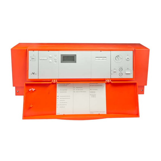
Vitotronic 100 Boiler Control Unit Introduction
Document Overview and Product Identification
Introduces the Vitotronic 100 control units (KC2B, KC4B) and the purpose of the installation manual.
General Safety Instructions and Precautions
Safety Instructions Explained
Explains warning symbols like Danger and Please note for risk and loss prevention.
Target Group and Regulations
Defines intended users as qualified contractors and lists applicable regulations.
Safety for System Operation
Details safety measures for working on the system, including electrical safety and handling hot surfaces.
Operating Safety and Hazard Prevention
Component and Spare Parts Safety
Emphasizes using tested spare parts and avoiding unauthorized modifications for safety.
Gas and Flue Gas Safety
Covers safety procedures for gas leaks, flue gas poisoning, and condensate handling.
Combustion Air and Extractor Safety
Addresses risks associated with combustion air supply and negative pressure from extractors.
Product Information and Safety
Packaging Disposal and Document Symbols
Provides instructions for packaging disposal and explains the meaning of various document symbols.
Intended Use and Application Guidelines
Defines the appliance's intended use for heating water and important application prerequisites.
Product Information and System Examples
Vitotronic 100 Control Unit Description
Details control units for constant temperature operation in single boiler systems.
System Examples and Usage
Provides links to system examples and notes on room temperature-dependent operation.
Installation Sequence: Control Unit and Coding
Opening the KC4B Control Unit
Illustrates the procedure for opening the KC4B control unit with safety notes.
Inserting the Boiler Coding Card
Explains how to insert the coding card into slot "X7" for proper boiler identification.
Coding Card and Safety Cut-out Adjustment
Coding Card Identification Table
Lists boilers and their corresponding coding card identification, display scan, and part numbers.
Adjusting High Limit Safety Cut-out
Details how to adjust the high limit safety cut-out from 110°C to 100°C with a note on temperature controller limits.
Adjusting the High Limit Safety Cut-out
KC2B High Limit Cut-out Adjustment
Provides figures and steps for adjusting the high limit safety cut-out on the KC2B unit.
KC4B High Limit Cut-out Adjustment
Provides figures and steps for adjusting the high limit safety cut-out on the KC4B unit.
Temperature Controller Adjustment Procedures
KC2B/KC4B High Limit Cut-out Adjustment (Cont.)
Continues the procedure for adjusting the high limit safety cut-out with diagrams.
Adjusting the Temperature Controller
Explains how to adjust the temperature controller from 75°C to 87/95°C, with safety notes.
Temperature Controller Adjustment Details
KC2B Temperature Controller Adjustment
Illustrates the steps for adjusting the temperature controller on the KC2B unit.
KC4B Temperature Controller Adjustment
Illustrates the steps for adjusting the temperature controller on the KC4B unit.
Electrical Connections Overview and Safety
Wiring Safety and Electrostatic Discharge
Highlights dangers of incorrect wiring and precautions against electrostatic discharge.
Electrical Connection Diagram and Layout
Shows the overall electrical connection diagram with labels for components and terminals.
PCB Connections and Cable Installation
Low Voltage and 230V~ PCB Connections
Details components connected to the low voltage and 230V~ PCB plugs.
Cable Entry and Strain Relief Procedures
Explains sealing apertures and routing cables with cast-on entries using strain relief.
Sensor and Pump Wiring
Cable Entry Without Cast-on Entry
Illustrates inserting cables without a cast-on entry.
Connecting Temperature Sensors
Lists plugs and corresponding temperature sensors for connection.
Connecting Pumps to 230V~ PCB
Details the available pump connections on the 230V~ PCB.
Pump Connection Variations
Connecting Standard 230V~ Pumps
Shows wiring for standard 230V~ pump connection to the control unit.
Connecting High-Power/High-Efficiency Pumps
Illustrates connections for pumps with switching input and without switching input.
Advanced Electrical Connections
Connecting 400V~ Pumps
Details wiring for 400V~ pumps via a contactor.
External Burner Start and Provisional Operation
Explains external burner start connection and enabling provisional burner operation.
External Control Inputs and Signals
External Demand via Switching Contact
Describes connecting external demand via plug 96 or EA1 extension, with coding options.
External Demand via 0-10V Input
Explains connecting external demand using a 0-10V input to the EA1 extension.
External Control Signals and Blocking
0-10V Input Signal Interpretation
Details how 0-10V input values translate to specified boiler water temperatures.
External Blocking via Switching Contact
Covers connecting external blocking signals via plug 96, EA1, or plug 150.
Blocking and Burner Connections
External Blocking Codes and Safety Notes
Provides coding for external blocking and notes on frost protection.
Connecting Pressure-Jet Oil/Gas Burners
Details connection for pressure-jet burners, including terminal codes and power consumption.
Burner Connection Types
Pressure-Jet Burner Terminal Codes
Lists terminal codes, signal flow, and color coding for pressure-jet oil/gas burners.
Connecting Atmospheric Burners
Describes connecting atmospheric burners to the system.
Burner and Extension Wiring
Atmospheric Burner Terminal Designations
Lists terminal designations and color coding for atmospheric burner connections.
Connecting 2-Stage Burner Extension
Details wiring for a 2-stage burner extension, including relays.
Power Supply and Electrical Safety
Main Power Supply and Isolator Requirements
Covers mains isolators, emergency stops, and RCDs for safety.
Accessory Power and Combustion Equipment Regulations
Discusses power for accessories and regulations for oil/gas combustion equipment.
Electrical Safety Standards and Cable Specs
Highlights safety standards, earthing, core assignment, and recommended power cable.
Accessory Power Supply Options
Powering Accessories via Control Unit
Illustrates powering multiple accessories through the control unit.
Direct Power Supply for Accessories
Shows connecting accessories directly to mains, with notes on exceeding total current.
Control Unit Power Connection
Connecting the Control Unit to Mains Power
Details steps for connecting the control unit's power cable, including fuse protection and isolator.
Commissioning Procedures
Testing High Limit Safety Cut-out
Step-by-step guide for testing the high limit safety cut-out on KC2B and KC4B units.
Coding Addresses and Actuator Tests
Explains matching coding addresses and performing actuator tests for system configuration.
Actuator Test Details
Actuator Test Display and Explanations
Lists display codes and their explanations for testing actuators like burners and pumps.
Coding Level Access and Reset
Accessing Coding Levels 1 and 2
Provides instructions for accessing and navigating Coding Level 1 and Coding Level 2.
Resetting Coding Settings to Default
Explains how to reset all coding settings to their factory-delivered condition.
Coding Level 1: General and Boiler Settings
General System Configuration (Group 1)
Covers system design, pump function, and external demand temperature settings.
Boiler Specific Settings (Group 2)
Details burner type, gas/oil operation, temperature limits, flue gas monitoring, and service intervals.
Coding Level 1: Boiler, DHW, and Solar
Boiler Service Status and Intervals
Configures service intervals in months and displays service status.
DHW Heating Control Types
Sets cylinder heating control and DHW reheating suppression.
Solar Pump Speed and Cylinder Settings
Configures solar pump speed control and maximum cylinder temperature for solar systems.
Coding Level 1: Solar and Heating Circuit 1
Solar System Optimization Functions
Adjusts stagnation time reduction, flow rate, and various solar control functions.
Heating Circuit 1 Configuration
Sets DHW priority, minimum/maximum flow temperatures, and heating circuit pump control.
Coding Level 1: Heating Circuit 1 Standby
Heating Circuit Pump Standby Mode Control
Configures heating circuit pump operation in standby mode, including run-on and pause times.
Coding Level 2: General Settings
General System Design and EA1 Inputs
Configures system design, EA1 extension inputs for external demand, blocking, and fault messages.
Coding Level 2: General Function Controls
General Inputs: Room Control and Burner Start
Configures room temperature control, external burner start, and blocking inputs.
Buffer Sensor and Solar System Settings
Sets buffer temperature sensor recognition and solar thermal system configuration.
Fault Reporting and Display Unit Settings
Configures fault reporting duration and temperature display units.
Coding Level 2: Boiler Operation
General External Demand and Boiler Limits
Adjusts external demand temperature and boiler water temperature limits.
Boiler Operation Parameters
Configures burner type, hysteresis, delays, and flue gas monitoring.
Coding Level 2: Boiler Service and DHW
Boiler Service Intervals and Fuel Consumption
Sets burner service intervals, fuel consumption metering, and burner ignition intervals.
DHW Cylinder Heating Control
Configures cylinder heating hysteresis and DHW temperature settings.
Coding Level 2: DHW and Solar Parameters
DHW Cylinder Temp and Control Sequences
Defines cylinder heating control, temp limits, and pump run-on times.
Solar Circuit Pump Control Logic
Configures solar pump switching based on collector and DHW temperatures.
Coding Level 2: Solar System Functionality
Solar Pump Speed and Temp Differentials
Adjusts solar pump speed, controller amplification, and temp differentials for various functions.
Solar System Protection and Monitoring
Configures frost protection, flow rate monitoring, and heat statement for solar systems.
Coding Level 2: Solar Heating Control
Solar Target Temp and Collector Settings
Sets target temperature control, solar DHW temperature, and minimum collector temperature.
Solar Heating Functions and Backup
Configures extended solar control functions, thermostat functions, and central heating backup.
Coding Level 2: Solar and Heating Circuit
Solar Thermostat and DHW Priority Settings
Configures thermostat start/stop temps and DHW cylinder priority for heating.
Heating Circuit Pump Operation Modes
Sets heating circuit pump modes, run-on times, and cyclical heating/pause times.
Coding Level 2: Heating Circuit Pump Control
Heating Circuit Pump Priority and Flow Limits
Configures cylinder priority, min/max flow temp limits for heating circuits.
Heating Circuit Pump Control Modes
Sets heating circuit pump behavior for external blocking/demand signals and run-on times.
Service Checks and Data Retrieval
Service Level Access and Exit
Guides users on how to enter and exit the service level menu.
Operating Data and Brief Scan Functions
Explains how to check, reset operating data, and perform a brief scan.
Service Check: Brief Scan Details
Brief Scan Display Options
Lists parameters available for brief scan, like software versions and temperatures.
Service Display and Acknowledgement
Interpreting and Acknowledging Service Displays
Explains how to interpret service displays, acknowledge them, and reset service parameters.
Troubleshooting: Fault Display and Codes
Understanding and Acknowledging Faults
Details how fault codes are displayed, acknowledged, and managed in the fault memory.
Fault Code Table and Measures
Provides a table of fault codes, their causes, and recommended measures for resolution.
Troubleshooting Specific Faults (Codes 30-93)
Fault Codes for Sensors and Pumps
Lists fault codes related to temp sensors, pumps, and solar control modules with causes and measures.
Troubleshooting Specific Faults (Codes 94-b7)
Fault Codes for Solar, Communication, and Cards
Lists fault codes for solar heating, communication errors, internal faults, and coding card issues.
Troubleshooting: Non-Displayed Faults
Boiler Start and Pump Operation Issues
Addresses issues where the boiler does not start or pumps are not running, including fuse checks.
Troubleshooting Pump and Sensor Issues
Heating Circuit Pump Not Running Troubleshooting
Details steps when the heating circuit pump is not running despite sufficient boiler temperature.
Checking Temperature Sensors
Provides guidance and resistance curves for checking boiler, cylinder, and buffer temperature sensors.
Sensor and Fuse Checks
Checking Flue Gas Temperature Sensor
Explains how to check the flue gas temperature sensor using a resistance curve.
Fuse Inspection and Replacement Procedures
Details procedures for checking and replacing fuses, including safety warnings.
Parts Ordering Information
Details Required for Ordering Parts
Lists necessary info (serial number, assembly, position number) for ordering spare parts.
Parts List: KC2B Casing Assembly
KC2B Casing Components Diagram
Illustrates KC2B casing assembly components with part numbers.
Parts List: KC2B Casing Components
KC2B Casing Assembly Parts Description
Lists and describes individual parts in the KC2B casing assembly.
Parts List: KC2B PCB Assembly
KC2B PCB Components Diagram
Illustrates KC2B PCB assembly components with part numbers.
Parts List: KC2B PCB Components
KC2B PCB Assembly Parts Description
Lists and describes individual parts of the KC2B PCB assembly.
Parts List: KC4B Casing Assembly
KC4B Casing Components Diagram
Illustrates KC4B casing assembly components with part numbers.
Parts List: KC4B Casing Components
KC4B Casing Assembly Parts Description
Lists and describes individual parts in the KC4B casing assembly.
Parts List: KC4B PCB Assembly
KC4B PCB Components Diagram
Illustrates KC4B PCB assembly components with part numbers.
Parts List: KC4B PCB Components
KC4B PCB Assembly Parts Description
Lists and describes individual parts of the KC4B PCB assembly.
Function Description: Boiler Water Temperature
Boiler Water Temperature Regulation
Explains how boiler water temp is regulated by burner switching, including set points and control limits.
Burner Hysteresis and Operating Modes
Details burner switching hysteresis and system protection modes for DHW and standby.
Function Description: Control Sequences
Boiler Temperature Control Sequences
Describes boiler heating and cooling sequences based on set values and switching differentials.
Cylinder Temperature Control and DHW
Explains cylinder thermostat function, DHW heating, priority control, and frost protection.
Function Description: Cylinder Heating Control
Cylinder Heating Control Modes
Details cylinder heating control modes, including adaptive heating and pump behavior.
DHW Auxiliary Functions and Control Logic
Covers auxiliary DHW functions and control logic for cylinder heating and solar systems.
Function Description: EA1 Extension Module
EA1 Extension Wiring and Inputs
Illustrates EA1 extension wiring and describes digital inputs (DE1-DE3) and analogue input functions.
Input Function Assignment and Safety Notes
Explains how to assign input functions using coding addresses and provides safety notes for connections.
Function Description: External Extensions
EA1 Extension Coding and Output 157
Details coding addresses for EA1 extension temp demand and explains output 157 for fault messages.
External H5 Extension Connections
Outlines connections for external burner blocking, safety equipment, and flue gas dampers via H5 extension.
Function Description: H5 Extension Operations
External Burner Blocking and Safety Equipment
Describes connecting external burner blocking and safety equipment, with safety notes.
Temporary Burner Stage 1 Operation
Explains how to set up temporary burner stage 1 operation using a jumper.
Function Description: Motorised Flue Gas Damper
Motorised Flue Gas Damper Connection and Check
Details connection and function check for a motorised flue gas damper.
Function Description: Vitoair Draught Stabiliser
Vitoair Draught Stabiliser Functionality
Explains function check and motor fault diagnosis for the Vitoair draught stabiliser.
Connection and Wiring Diagram
Overall Wiring Diagram and Component Labels
Presents the comprehensive wiring diagram with labels for all connected components and terminals.
Technical Specifications
Electrical and Environmental Specifications
Lists electrical ratings, IP rating, function type, and permissible ambient conditions.
Relay Output Capacities
Details rated relay output breaking capacity for components like pumps and burners.
Settings and Equipment Configuration
Adjustable Control Functions
Allows ticking modified functions for high limit, temperature controller, limits, and hysteresis.
DHW Heating System and Accessories
Configures DHW heating system settings and lists compatible accessories.
Need help?
Do you have a question about the KC2B and is the answer not in the manual?
Questions and answers