Advertisement
YST-FSW150/YST-FSW050
• YST-FSW150
• YST-FSW050
I CONTENTS
TO SERVICE PERSONNEL .......................................... 2
INTERNAL VIEW ........................................................... 4
FRONT PANELS ............................................................ 5
REAR PANELS .......................................................... 6-7
1 0 1 0 6 1
SUBWOOFER SYSTEM
........................................ 3
2007
This manual is copyrighted by YAMAHA and may not be copied or
redistributed either in print or electronically without permission.
SERVICE MANUAL
IMPORTANT NOTICE
This manual has been provided for the use of authorized YAMAHA
Retailers and their service personnel.
It has been assumed that basic service procedures inherent to the industry,
and more specifically YAMAHA Products, are already known and
understood by the users, and have therefore not been restated.
WARNING:
Failure to follow appropriate service and safety
procedures when servicing this product may result in
personal injury, destruction of expensive components,
and failure of the product to perform as specified. For
these reasons, we advise all YAMAHA product owners
that any service required should be performed by an
authorized YAMAHA Retailer or the appointed service
representative.
IMPORTANT:
The presentation or sale of this manual to any individual
or firm does not constitute authorization, certification or
recognition of any applicable technical capabilities, or
establish a principle-agent relationship of any form.
The data provided is believed to be accurate and applicable to the unit(s)
indicated on the cover. The research, engineering, and service departments
of YAMAHA are continually striving to improve YAMAHA products.
Modifications are, therefore, inevitable and specifications are subject to
change without notice or obligation to retrofit. Should any discrepancy
appear to exist, please contact the distributor's Service Division.
WARNING:
Static discharges can destroy expensive components.
Discharge any static electricity your body may have
accumulated by grounding yourself to the ground buss in
the unit (heavy gauge black wires connect to this buss).
IMPORTANT:
Turn the unit OFF during disassembly and part
replacement. Recheck all work before you apply power
to the unit.
BLOCK DIAGRAM ....................................................... 12
PRINTED CIRCUIT BOARDS ................................ 13-14
SCHEMATIC DIAGRAMS ...................................... 15-16
REPLACEMENT PARTS LIST .............................. 17-25
All rights reserved.
........... 8-11
P.O.Box 1, Hamamatsu, Japan
'07.08
Advertisement
Table of Contents

Related Manuals for Yamaha FSW150 - YST Subwoofer - 75 Watt


Summary of Contents for Yamaha FSW150 - YST Subwoofer - 75 Watt
-
Page 1: Table Of Contents
REPLACEMENT PARTS LIST ......17–25 2007 All rights reserved. 1 0 1 0 6 1 This manual is copyrighted by YAMAHA and may not be copied or redistributed either in print or electronically without permission. P.O.Box 1, Hamamatsu, Japan '07.08... -
Page 2: To Service Personnel
YST-FSW150/YST-FSW050 I TO SERVICE PERSONNEL AC LEAKAGE WALL EQUIPMENT TESTER OR 1. Critical Components Information OUTLET UNDER TEST EQUIVALENT Components having special characteristics are marked s and must be replaced with parts having specifications equal to those originally installed. 2. Leakage Current Measurement (For 120V Models Only) When service has been completed, it is imperative to verify INSULATING that all exposed conductive surfaces are properly insulated... -
Page 3: Specifications
I SPECIFICATIONS / U ..U.S.A. model A ..Australian model • DIMENSIONS / Type / ..Advanced Yamaha Active Servo Technology II C ..Canadian model B ..British model Output Power / (100 Hz, 5 ohms, 10% T.H.D.) R .. -
Page 4: Internal View
YST-FSW150/YST-FSW050 I INTERNAL VIEW YST-FSW150 YST-FSW050 Power Transformer Power Transformer MAIN (7) P.C.B. (U, C, T, A, B, G, J models) MAIN (7) P.C.B. (U, C, T, K, A, B, G, J models) MAIN (8) P.C.B. (R, L models) MAIN (8) P.C.B. (R, L models) MAIN (4) P.C.B. -
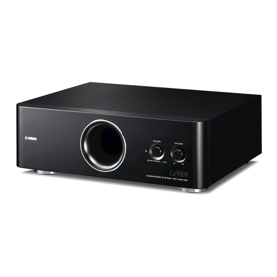
Page 5: Front Panels
YST-FSW150/YST-FSW050 I FRONT PANELS YST-FSW150 Power indicator • Front view • Bottom view U, C, J models R, L models YST-FSW050 Power indicator • Front view • Bottom view U, C, J models R, L models... -
Page 8: Disassembly Procedures
YST-FSW150/YST-FSW050 I DISASSEMBLY PROCEDURES / Disconnect the power cable from the AC outlet. • Required tools • Flatblade screwdriver • Metalblade or the like (with wider blade end) * Used when removing the bottom grille ass’y and front panel ass’y. 1. - Page 9 YST-FSW150/YST-FSW050 d. Remove 4 screws (1) and then pull out the driver. (Fig. 2) e. Disconnect the connector connected to the terminal of the Driver. (Fig. 2) Driver Fig. 2 2. Removal of bottom panel ass’y a. Remove 2 screws (2) and then remove 2 legs. (Fig. 3) b.
- Page 10 YST-FSW150/YST-FSW050 3. Removal of front panel ass’y * The front panel ass’y is fixed to the cabinet ass’y with dowels. As a flatblade screwdriver is used for removal, use special care not to cause damage to the cabinet ass’y. a. Remove 2 bushings. (Fig. 4) * Used bushing, once removed, cannot be reused.
- Page 11 YST-FSW150/YST-FSW050 4. Removal of rear panel ass’y a. Remove 8 screws (4). (Fig. 5) * Screws (4) are identified with arrow marks ( b. Remove the rear panel ass’y. (Fig. 5) c. Remove 2 bushings. (Fig. 5) * Used bushing, once removed, cannot be reused. Be sure to use a new bushing in place of the removed used bushing.
-
Page 12: Block Diagram
YST-FSW150/YST-FSW050 I BLOCK DIAGRAM YST-FSW150/YST-FSW050 VOLUME INPUT IC1A POWER IC1B DRIVER AMP. IC6A IC6B WOOFER L.P.F. L.P.F. H.P.F. 6dB/oct 12dB/oct 12dB/oct A.N.IC LIMITER Q5,6,7,8 SYSTEM CONTROL DRIVER PROTECTION Q10,11 Q2,4,9,12 POWER POWER SUPPLY REGULATOR AC IN POWER INDICATOR... -
Page 13: Printed Circuit Boards
YST-FSW150/YST-FSW050 YST-FSW150 I PRINTED CIRCUIT BOARDS • Semiconductor Location MAIN (1) P.C.B. (Side A) B, G models Ref no. Location Ref no. Location MAIN (3) P.C.B. (Side A) POWER OFF/SYSTEM VOLUME Power indicator DRIVER WOOFER W10A3 W10A2 W10A1 LEDG B, G models MAIN (2) P.C.B. - Page 14 YST-FSW150/YST-FSW050 YST-FSW050 • Semiconductor Location MAIN (1) P.C.B. (Side A) K, B, G models Ref no. Location Ref no. Location MAIN (3) P.C.B. (Side A) POWER OFF/SYSTEM VOLUME Power indicator DRIVER WOOFER W10A3 W10A2 W10A1 LEDG K, B, G models MAIN (2) P.C.B.
-
Page 15: Schematic Diagrams
YST-FSW150/YST-FSW050 SCHEMATIC DIAGRAMS YST-FSW150 MAIN MAIN (1) POWER AMP. +42.4 +42.4 +42.4 -11.2 MAIN (2) A.N.IC +14.8 – MAIN (4) L.P.F. -15.2 DRIVER IC1, 2, 6: NJM4558L WOOFER INPUT +14.8 Dual operational amplifier 4.7K 4.7K SYSTEM CONNECTOR H.P.F. +24.6 -15.2 LIMITER +14.8 IC3: STK404-120... - Page 16 YST-FSW150/YST-FSW050 YST-FSW050 MAIN MAIN (1) POWER AMP. +34.7 +34.7 +34.7 MAIN (2) A.N.IC +15.1 IC1, 2, 6: NJM4558L MAIN (4) – Dual operational amplifier L.P.F. -15.1 DRIVER WOOFER INPUT +15.0 3.3K 3.3K SYSTEM CONNECTOR H.P.F. +23.9 IC3: STK404-120 -15.1 Power amplifier LIMITER +15.0 L.P.F.
-
Page 17: Replacement Parts List
YST-FSW150/YST-FSW050 I REPLACEMENT PARTS LIST • ELECTRICAL COMPONENT PARTS WARNING G Components having special characteristics are marked s and must be replaced with parts having specifications equal to those originally installed. ABBREVIATIONS IN THIS LIST ARE AS FOLLOWS: C.A.EL.CHP : CHIP ALUMI.ELECTROLYTIC CAP L.EMIT : LIGHT EMITTING MODULE C.CE... - Page 18 YST-FSW150/YST-FSW050 YST-FSW150 P.C.B. MAIN ✻ New Parts...
- Page 19 YST-FSW150/YST-FSW050 YST-FSW150 P.C.B. MAIN ✻ New Parts...
- Page 20 YST-FSW150/YST-FSW050 YST-FSW050 P.C.B. MAIN ✻ New Parts...
- Page 21 YST-FSW150/YST-FSW050 YST-FSW050 P.C.B. MAIN ✻ New Parts...
- Page 22 YST-FSW150/YST-FSW050 • OVERALL ASS’Y YST-FSW150 *1 Used bushing, once removed, cannot be reused. Be sure to use a new bushing in place of the removed used bushing. 4-20 204 x 2 4-11 Packing C 4-20 Packing D 4-15 4-13 3-12 Packing D 203-2 Packing...
- Page 23 YST-FSW150/YST-FSW050 ✻ New Parts ✻ New Parts...
- Page 24 YST-FSW150/YST-FSW050 YST-FSW050 *1 Used bushing, once removed, cannot be reused. Be sure to use a new bushing in place of the removed used bushing. 4-11 Packing C 4-20 Packing D 4-20 4-15 4-13 Packing D 3-12 4-14 3-11 *2 Packing C, D and G are not available as replacement parts.
- Page 25 YST-FSW150/YST-FSW050 ✻ New Parts...
- Page 26 YST-FSW150/YST-FSW050...
Need help?
Do you have a question about the FSW150 - YST Subwoofer - 75 Watt and is the answer not in the manual?
Questions and answers