
Related Manuals for ADCMT 6156


Summarization of Contents
Safety Summary
Warning Labels
Describes warning labels on products and their meanings.
Basic Precautions
Lists essential safety measures for using the instrument.
Caution Symbols Used Within this Manual
Explains caution symbols used in the manual.
Safety Marks on the Product
Details safety marks found on the instrument itself.
Replacing Parts with Limited Life
Discusses parts with limited lifespan and replacement procedures.
Preface
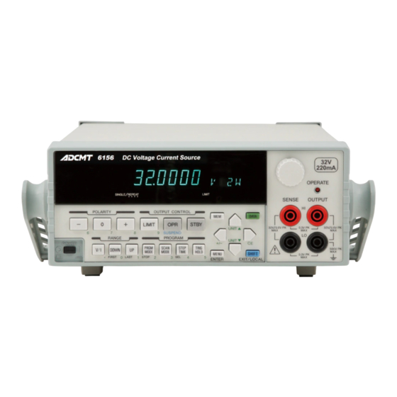
Product Overview
Describes the general features and characteristics of the 6146/6156.
Operating Environment
Environmental Conditions
Details ambient temperature, humidity, and location requirements.
Operation
Panel Description
Describes the layout and functions of the instrument's front and rear panels.
Front Panel
Display Section
Explains the vacuum fluorescent display and its indicators.
RANGE Section
Describes the keys related to selecting voltage/current and adjusting the range.
OUTPUT CONTROL Section
Explains the keys for controlling output operation (LIMIT, OPR, SUSPEND, STBY).
POLARITY Section
Describes the keys for setting the output polarity and zero.
PROGRAM Section
Details the keys for selecting program modes (PRGM MODE, SCAN MODE, etc.).
Other Keys
Describes various other keys like MENU, MEM, DATA, cursor keys, rotary knob, SHIFT, EXIT, LOCAL, ENTER.
Output Section
Explains the output terminals and the OPERATE indicator.
POWER Switch
Describes the function of the power switch.
Basic Operation
Setting Source Value
Explains how to set the desired output voltage or current.
Setting Source Value
Relation between Keys
Illustrates how different keys interact for source value setting.
Setting Source Value Using Cursor Keys/Rotary Knob (Auto Range OFF)
Details setting source values when auto-ranging is disabled.
Setting Source Value Using Cursor Keys/Rotary Knob (Auto Range ON)
Explains setting source values with auto-ranging enabled.
Setting Source Value Using Direct Data Input Mode
Describes entering values directly using the numeric keypad.
Initializing Setting Conditions
Initializing the setting parameters
Describes how to initialize all user-set parameters.
Factory default settings
Explains how to reset the instrument to its factory default configuration.
Program Mode
Memory Recall Mode
Explains how to save and recall source settings in memory.
Memory Recall Mode
Memory Setting
Describes the process of setting up memory data for recall.
Sweep Source Mode
Setting Sweep Conditions
Outlines the parameters required to set up a sweep operation.
Thermal Electromotive Force Output
Thermal Electromotive Force Output Operation
Explains how to turn the function ON/OFF and set temperature values.
Saving and Loading Parameters
Auto Load at Power ON
Describes how the instrument loads settings automatically upon startup.
Reference
Menu Index
Provides an alphabetical listing of menu items and their page numbers.
Function Description
Parameter Save (*SAV0, *SAV1, *SAV2, *SAV3, SINI)
Details commands for saving instrument parameters to non-volatile memory.
Interface Selection (BUS, GPIB, USB, BCD)
Explains how to select and configure communication interfaces.
System Parameters (SYS)
Describes settings related to system-wide parameters like buzzers and tests.
Calibration Mode (CAL)
Explains how to enter and exit the instrument's calibration mode.
Technical References
Load Connection
Describes how to connect the load to the instrument.
Functions in Detail
Operations in DC Source Mode
Explains how operations are performed in DC source mode.
Source Function
Source Mode, Source Function and Setting Parameters
Outlines the relationships between modes, functions, and parameters.
Limiter
Limiter Setting Ranges
Specifies the settable ranges for voltage and current limiters.
Setting Limiters
Describes the types of limiter settings (LMT.HL OFF/ON) and how to configure them.
READY OUT/SYNC OUT
Restrictions on Using External Trigger
Lists limitations and precautions for using the external trigger.
Operating Multiple 6146/6156
Synchronous Operation
Explains how to synchronize multiple units for timing control.
Operational Principles
Block Diagram
Presents a block diagram illustrating the instrument's internal structure.
Operational Principles
Explains the functional principles of the instrument's circuits.
Remote Programming
Using Interface
Explains how to use the available interfaces (GPIB, USB, BCD).
USB
Overview
Provides a general introduction to the USB interface.
USB Specifications
Details the technical specifications of the USB interface.
BCD (Option 04)
Overview
Provides a general introduction to the BCD interface.
Setting BCD Interface
Explains how to enable and configure the BCD interface.
Status Register Structure
Status Register
Provides an overview of the status register, including Event and Enable Registers.
Remote Commands
Command Syntax
Explains the format for constructing commands sent to the instrument.
Sample Program
Common Sub Procedures for Interface Control
Provides reusable code snippets for controlling interfaces.
Performance Test
Measuring Instruments Necessary for Performance Test
Lists the instruments required for performance testing.
Connections
Refers to connection diagrams for performance testing.
Test Method
Outlines the procedures for conducting performance tests.
Calibration
Preparation for Calibration
Describes the prerequisites for calibration.
Calibration Method
Calibration Points and Tolerance Ranges
Specifies the points and acceptable tolerances for calibration.
Specifications
Voltage/Current Source
Details the specifications for voltage and current sourcing capabilities.
Appendix
When Problems Occur (Before Requesting Repairs)
Offers troubleshooting steps for common issues.
Execution Time
GPIB/USB Remote Execution Time (Typical Value)
Lists typical execution times for remote commands via GPIB and USB.
Internal Processing Time (Typical Value)
Source processing time
Details the time taken for source value changes after Operate input.
Need help?
Do you have a question about the 6156 and is the answer not in the manual?
Questions and answers