Sign In
Upload
Download
Table of Contents
Contents
Add to my manuals
Delete from my manuals
Share
URL of this page:
HTML Link:
Bookmark this page
Add
Manual will be automatically added to "My Manuals"
Print this page
×
Bookmark added
×
Added to my manuals
Manuals
Brands
ADCMT Manuals
Portable Generator
6146
Operation manual
ADCMT 6146 Operation Manual
Dc voltage/current generators
Hide thumbs
1
2
3
4
5
6
7
8
9
10
Table Of Contents
11
12
13
14
15
16
17
18
19
20
21
22
23
24
25
26
27
28
29
30
31
32
33
34
35
36
37
38
39
40
41
42
43
44
45
46
47
48
49
50
51
52
53
54
55
56
57
58
59
60
61
62
63
64
65
66
67
68
69
70
71
72
73
74
75
76
77
78
79
80
81
82
83
84
85
86
87
88
89
90
91
92
93
94
95
96
97
98
99
100
101
102
103
104
105
106
107
108
109
110
111
112
113
114
115
116
117
118
119
120
121
122
123
124
125
126
127
128
129
130
131
132
133
134
135
136
137
138
139
140
141
142
143
144
145
146
147
148
149
150
151
152
153
154
155
156
157
158
159
160
161
162
163
164
165
166
167
168
169
170
171
172
173
174
175
176
177
178
179
180
181
182
183
184
185
186
187
188
189
190
191
192
193
194
195
196
197
198
199
200
201
202
203
204
205
206
207
208
209
210
211
212
213
214
215
216
217
218
219
220
221
222
223
224
225
226
227
228
229
230
231
232
233
234
235
236
237
238
239
240
241
242
243
244
245
246
247
248
249
250
251
252
253
254
255
256
257
258
259
260
page
of
260
Go
/
260
Contents
Table of Contents
Bookmarks
Table of Contents
Table of Contents
Preface
Product Overview
Supplied Accessories
Standard Accessory List
Optional Accessories
Options
Optional Accessory List
Option List
Operating Environment
Environmental Conditions
Operating Environment
Power Specification
Set Power Voltage Indicator
Power Supply Specification
Changing Power Voltage, and Checking and Replacing Power Fuse
Power Cable
Operating Check
Connecting the Power Cable
Model Name and Software Revision Display
Model Name and Interface Display
Start-Up Screen
Cleaning, Storage, and Transport Methods
Storage
Transport
Warm-Up Time
Calibration
1.10 Life Limited Parts
1.11 Product Disposal and Recycling
Operation
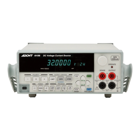
Panel Description
Front Panel
Display Section
Display Section
RANGE Section
OUTPUT CONTROL Section
POLARITY Section
PROGRAM Section
Other Keys
Output Section
POWER Switch
Screen Display (Annotations)
Rear Panel
Basic Operation
Setting Source Value
Relation between Keys
Setting Source Value Using Cursor Keys/Rotary Knob (Auto Range OFF)
Setting Source Value Using Cursor Keys/Rotary Knob (Auto Range ON)
Setting Source Value Using Direct Data Input Mode
Setting Limit Values
Menu Operation
Menu Operation Overview
How to Operate Menu
Menu and Key Functions
Menu Structure and Parameter Setting
Initializing Setting Conditions
Setting Parameter Initial Values
Polarity Setting Mode (Unipolar/Bipolar)
2.2.6 Count Fix Function
Stby in
Opr/Stby in
Opr Sus in
Memory Recall Mode
Sweep Source Mode
Internal Wire Connection
Preventing Oscillation
Source and Sink Zones
Error Due to Lead Resistance in 4-Wire Connection
Operations in DC Source Mode
Operations Using Continuous Function
Operations in Memory Recall Mode
Operations in Sweep Source Mode
Shifting between Operate, Standby and Suspend
Conceptual Diagram of Output Status
Output Statuses and Internal Setting Values
Image of Grounded Load
Alarm Detection Contents
Response Change by Limit Value for Voltage Source
Response Change by Limit Value for Current Source
External Control Signal Functions
TRIGGER in Operations
TRIGGER in Input Circuit
READY OUT/SYNC out Output Circuit
OPERATE/STANDBY in Signal and Its Output Status
Operate out
INTERLOCK Signal and Its Output Status
Connection for Three Unit Synchronous Operation Using OPERATE out
Setting for Three Unit Synchronous Operation Using OPERATE out
Connection for Three Unit Synchronous Operation Using SYNC out
Setting for Three Unit Synchronous Operation in Sweep Source Mode Using SYNC out
Setting for Three Unit Synchronous Operation in Memory Recall Mode Using SYNC out
Serial Connection
Parallel Connection
Self-Test Items
Self-Test Operation
Block Diagram
Interface Function
Standard Bus Cable
BCD Parallel Connector Pin Arrangement and Code List
BCD Interface Input Equivalent Circuit
Status Register Structure
Status Byte Register Structure
Standard Event Status Register (ESR)
Device Event Status Register (DSR)
Status Byte Register Structure in 6144-Compatible Mode
Status Byte Register (STB) in 6144-Compatible Mode
Accuracies and Cables Necessary for Calibration
Connections for Calibration
Calibration Tolerance Ranges
Outlined Calibration Procedure
DAC Calibration Procedure
Remote Calibration Procedure
Remote Calibration Procedure (Voltage Source)
Remote Calibration Procedure (Voltage Limiter)
Remote Calibration Procedure (Current Source)
Remote Calibration Procedure (Current Limiter)
Manual Calibration Procedure
Manual Calibration Explanatory Diagram
Items to be Inspected before Requesting Repair
A.2 Error Message List
Advertisement
Quick Links
1
Table of Contents
2
A.2 Error Message List
Download this manual
Cover
6146/6156
DC Voltage/Current Generators
Operation Manual
FOE-00000064C00
MANUAL NUMBER
Applicable Models
6146
6156
First printing November 26, 2010
C
2010
ADC CORPORATION
All rights reserved.
Printed in Japan
Table of
Contents
Previous
Page
Next
Page
1
2
3
4
5
Advertisement
Table of Contents
Need help?
Do you have a question about the 6146 and is the answer not in the manual?
Ask a question
Questions and answers
Related Manuals for ADCMT 6146
Portable Generator ADCMT 6247G Operation Manual
Dc voltage current source/monitor (284 pages)
Portable Generator ADCMT 6156 Operation Manual
Dc voltage/current generators (260 pages)
This manual is also suitable for:
6156
Table of Contents
Save PDF
Print
Rename the bookmark
Delete bookmark?
Delete from my manuals?
Login
Sign In
OR
Sign in with Facebook
Sign in with Google
Upload manual
Upload from disk
Upload from URL


Need help?
Do you have a question about the 6146 and is the answer not in the manual?
Questions and answers