
Related Manuals for ADCMT 6247G


Summary of Contents for ADCMT 6247G
- Page 1 Cover 6247G/6247C DC Voltage Current Source/Monitor Operation Manual FOE-00000088B00 MANUAL NUMBER Applicable Models 6247G 6247C First printing Oct 31, 2013 ADC CORPORATION 2013 All rights reserved. Printed in Japan...
-
Page 3: Table Of Contents
TABLE OF CONTENTS 6247G/6247C DC Voltage Current Source/Monitor Operation Manual TABLE OF CONTENTS PREFACE ...................... Product Overview ....................Supplied Accessories ..................Optional Accessories ..................Operating Environment ..................1.4.1 Environmental Conditions ................1.4.2 Power Specification ..................1.4.3 Changing Power Voltage, and Checking and Replacing Power Fuse .. - Page 4 6247G/6247C DC Voltage Current Source/Monitor Operation Manual Table of Contents 2.2.3.2 Menu Structure and Parameter Setting ............2-28 2.2.4 Initializing Setting Conditions ..............2-34 2.2.5 DC Measurement ..................2-35 2.2.6 Pulse Measurement ..................2-39 2.2.7 Sweep Measurement ................... 2-43 Saving and Loading Parameters ................
- Page 5 6247G/6247C DC Voltage Current Source/Monitor Operation Manual Table of Contents 5.2.3 Operations in Sweep Source Mode ............5-12 5.2.3.1 Operations in DC Sweep Source Mode ............5-15 5.2.3.2 Operations in Pulse Sweep Source Mode ........... 5-17 5.2.3.3 Random Sweep and Random Pulse Sweep ..........
- Page 6 6247G/6247C DC Voltage Current Source/Monitor Operation Manual Table of Contents 5.4.1 Block Diagram .................... 5-72 5.4.2 Operational Principles ................5-72 REMOTE PROGRAMMING ..............Using Interface ....................6.1.1 Selecting Interface ..................GPIB ........................6.2.1 Overview ....................6.2.2 Precautions when Using GPIB ..............
- Page 7 6247G/6247C DC Voltage Current Source/Monitor Operation Manual Table of Contents Safety Precautions ..................... Connections ....................... Calibration Points and Tolerance Ranges ............Calibration Procedure ..................8.5.1 Overall Calibration Procedure ..............8-13 8.5.2 Voltage Source/Voltage Limiter Calibration ..........8-13 8.5.3 Voltage Measurement Calibration ..............
- Page 9 6247G/6247C DC Voltage Current Source/Monitor Operation Manual LIST OF ILLUSTRATIONS Title Page Operating Environment ..................... Set Power Voltage Indicator ..................... Power Cable ........................Connecting Power Cable ....................1-10 Self-Test in Progress ......................1-11 Self Test Completion ......................1-11 Start-Up Display .......................
- Page 10 6247G/6247C DC Voltage Current Source/Monitor Operation Manual List of Illustrations Title Page Connection for High Current Measurement ..............Connection with 12701A ....................Random Sweep and Random Pulse Sweep ............... 5-18 2-Slope Linear Sweep ....................... 5-19 5-10 2-Slope Linear Pulse Sweep .....................
- Page 11 6247G/6247C DC Voltage Current Source/Monitor Operation Manual LIST OF TABLES Title Page Standard Accessory List ....................Optional Accessory List ....................Power Supply Specification ....................Menu and Keys Functions ....................2-27 Default Parameter List ...................... 2-51 Integration Time and Indicator Display ................
-
Page 13: Preface
In addition, it is equipped with not only the various types of sweep functions but also the pulse mea- surement function with the minimum pulse width of 50 s. By using these functions, the 6247G/6247C can be widely used as ideal SMU for evaluating or testing semiconductor and other electronic components. -
Page 14: Supplied Accessories
6247G/6247C DC Voltage Current Source/Monitor Operation Manual 1.2 Supplied Accessories Supplied Accessories The 6247G/6247C standard accessories are listed below. If any accessory is missing or damaged, contact an ADC CORPORATION sales representative. Specify the part number when ordering. Table 1-1 Standard Accessory List... -
Page 15: Optional Accessories
As the rack mount set is not rigid enough to support the instrument by itself, use angle bars to mount the 6247G/6247C on the rack mount set. Contact an ADC CORPORATION sales representative for rack setup and other technical support. -
Page 16: Operating Environment
Obstructing the vents will cause the internal temperature to rise, possibly causing faulty operation. • Mounting in a rack Ensure that exhaust air from other devices is not directed at the vents on the side of the 6247G/6247C. To prevent the temperature in the rack from rising, install a heat sink fan. -
Page 17: Operating Environment
• Keep the rear panel more than 10 centimeters away rear panel facing down. from the wall Figure 1-1 Operating Environment NOTE: Warm-up Time Allow the 6247G/6247C to warm up for at least 60 minutes after turning on the power to ensure the spec- ified accuracy of the 6247G/6247C. -
Page 18: 1.4.2 Power Specification
1.4.2 Power Specification 1.4.2 Power Specification Table 1-3 below shows the 6247G/6247C power supply specifications. CAUTION: To prevent damage to the 6247G/6247C, do not apply a voltage or frequency that exceeds the spec- ified range. Table 1-3 Power Supply Specification Optional Standard... -
Page 19: Set Power Voltage Indicator
6247G/6247C DC Voltage Current Source/Monitor Operation Manual 1.4.2 Power Specification Ensure that the power voltage setting on the instrument rear panel matches the voltage of the commercial power supply. Voltage setting indicator 6247G Voltage setting indicator 6247C Figure 1-2 Set Power Voltage Indicator... -
Page 20: Changing Power Voltage, And Checking And Replacing Power Fuse
1.4.3 Changing Power Voltage, and Checking and Replacing Power Fuse 1.4.3 Changing Power Voltage, and Checking and Replacing Power Fuse The 6247G/6247C power voltage can be changed manually. This section describes the procedure for changing the power voltage, and checking and replacing the power fuse. -
Page 21: Power Cable
6247G/6247C DC Voltage Current Source/Monitor Operation Manual 1.4.4 Power Cable Insert a rated fuse (See Table 1-3). Return the fuse holder assembly into the rear panel. Verify that a rated fuse is installed and that the correct power voltage appears in the window. -
Page 22: Operating Check
1.5 Operating Check Operating Check This section describes the simple self-test which must be performed when operating the 6247G/6247C for the first time. Follow the procedure below to ensure the instrument operates correctly. Ensure that the POWER switch on the front panel is set to OFF. -
Page 23: Self-Test In Progress
6247G/6247C DC Voltage Current Source/Monitor Operation Manual 1.5 Operating Check Turn ON the POWER switch on the front panel. After all the indicators turn on, a self-test is performed. (Duration: approx. 15 sec. See Figure 1-5.) Figure 1-5 Self-Test in Progress... -
Page 24: Vsvm Measurement (Output Off)
Verify that the VM measured value is within 350 V of 0 V in the VS 5 V range. Press STBY. The OPR indicator goes OFF and the 6247G/6247C enters the Standby (output OFF) status. The operation check is complete. -
Page 25: Cleaning, Storage, And Transport Methods
(90 days or longer), place the 6247G/6247C in a moisture-proof bag together with a desiccant. Avoid storing the 6247G/6247C in a location where there is a lot of dust or where it will be subjected to direct sunlight. -
Page 26: Warm-Up Time
6247G/6247C DC Voltage Current Source/Monitor Operation Manual 1.7 Warm-up Time Warm-up Time Allow the 6247G/6247C to warm up for at least 60 minutes after turning on the power to ensure the specified accuracies of the 6247G/6247C. Calibration Calibrate the 6247G/6247C in accordance with the procedure described in Chapter 8 "CALIBRATION."... -
Page 27: 1.10 Product Disposal And Recycling
1.10 Product Disposal and Recycling 1.10 Product Disposal and Recycling Correctly dispose of the 6247G/6247C in accordance with local and national regulations. Before disposal, remove the following parts from the product to prevent dispersal of substances that may adversely affect the environment, human health, or the ecosystem. - Page 28 6247G/6247C DC Voltage Current Source/Monitor Operation Manual 1.10 Product Disposal and Recycling Name of substance or removed part Used? Location Unit Part Nickel or its compounds Unit Electronic compo- nents, mechanical components Lead or its compounds Unit BPQ-013001 Lead solder used for...
-
Page 29: Operation
6247G/6247C DC Voltage Current Source/Monitor Operation Manual 2. OPERATION OPERATION This chapter describes the part names and functions on the front and rear panels and screen display (annota- tions) elements. The basic operations are explained by using measurement examples. Panel Descriptions This section describes the part names and functions on the front and rear panels, and the screen display (anno- tation) elements. -
Page 30: Display Section
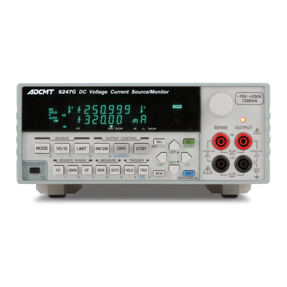
6247G/6247C DC Voltage Current Source/Monitor Operation Manual 2.1.1 Front Panel 2.1.1.1 Display Section Figure 2-2 Display Section Display: The screen employs a vacuum fluorescent display. It displays the source value, the measurement value and the unit operational status. It functions as the setting screen when changing the setting parameters. -
Page 31: Source Range Section
6247G/6247C DC Voltage Current Source/Monitor Operation Manual 2.1.1 Front Panel 2.1.1.3 SOURCE RANGE Section Figure 2-4 SOURCE RANGE Section FIT key: Selects the optimum fitting range (FIT) or the currently setting range to input the source values. DOWN key: Lowers the source range. -
Page 32: Output Control Section
6247G/6247C DC Voltage Current Source/Monitor Operation Manual 2.1.1 Front Panel 2.1.1.5 OUTPUT CONTROL Section 2, 3 Figure 2-6 OUTPUT CONTROL Section 4W/2W key: Selects the output sensing 4-wire or 2-wire connection. OPR key: Switches between Operate and Suspend. * : Suspend status outputs the suspended voltage without turning OFF the output relays. -
Page 33: Other Keys
6247G/6247C DC Voltage Current Source/Monitor Operation Manual 2.1.1 Front Panel 2.1.1.7 Other Keys 7, 8, 9 Figure 2-8 Other Keys MENU key: Displays the menu. NULL key: Turns ON or OFF the NULL calculation. 123... key: Switches to the direct input mode, sets the value, and executes the source generation on the setting screen which accepts numerical input. -
Page 34: Output Section
6247G/6247C DC Voltage Current Source/Monitor Operation Manual 2.1.1 Front Panel 2.1.1.8 Output Section Figure 2-9 Output Section OUTPUT terminals: Voltage and current output terminals SENSE terminals: Functions as sensing terminals for voltage output and input termi- nals for voltage measurement in the remote sense mode (4-wire connection). -
Page 35: Screen Display (Annotations)
6247G/6247C DC Voltage Current Source/Monitor Operation Manual 2.1.2 Screen Display (Annotations) 2.1.2 Screen Display (Annotations) This section describes the screen display (annotations). Figure 2-11 Screen Display (Annotations) Source value Displays a voltage source (VS) or current source (IS) value with a unit. -
Page 36: Integration Time And Indicator Display
6247G/6247C DC Voltage Current Source/Monitor Operation Manual 2.1.2 Screen Display (Annotations) FMSL: Displays the measurement integration time by using the indicators in combination. For more information on this combination, refer to Table 4-1, "Integration Time and Indicator Display." AUTO: The auto range is set to ON. - Page 37 6247G/6247C DC Voltage Current Source/Monitor Operation Manual 2.1.2 Screen Display (Annotations) ERR: An error log is generated. CAL: Calibration mode is ON. OPR: Illuminates or extinguishes depending on the output status. Operate: ON Suspend: Blinks Standby: OFF When the comparator calculation is ON, either one of these three indicators goes ON depending on the results.
-
Page 38: Rear Panel
6247G 6247C Figure 2-12 Rear Panel AC power connector Connects the 6247G/6247C to the AC power supply by using the supplied power cable. Voltage selector and fuse holder Selects voltage manually to match the AC power supply. A fuse is contained inside. - Page 39 6247G/6247C DC Voltage Current Source/Monitor Operation Manual 2.1.3 Rear Panel TRIGGER IN Functions as a DC or pulse measurement trigger and a sweep start or step-up trigger. The input resistance is about 4.7 k and is TTL negative pulse input. (Pulse width 2 s or over) COMPLETE OUT | SYNC OUT The output signal is a negative pulse.
-
Page 40: Basic Operation
6247G/6247C DC Voltage Current Source/Monitor Operation Manual 2.2 Basic Operation Basic Operation This section describes the following items: • Setting the source value • Setting the limit values • How to use the menu and basic measurement functions NOTE: The operation procedures listed permit the settings to be made in the shortest time. If the display differs from the one shown, repeat the procedure from the beginning. -
Page 41: Setting Source Value Using Cursor Keys/Rotary Knob (With Fit Indicator Off)
6247G/6247C DC Voltage Current Source/Monitor Operation Manual 2.2.1 Setting Source Value 2.2.1.2 Setting Source Value Using Cursor Keys/Rotary Knob (with FIT Indicator OFF) Change the source value using the cursor keys ( ) and the UP/DOWN keys ( ) or the rotary knob ( keys move the cursor (blinking) position left and right. - Page 42 6247G/6247C DC Voltage Current Source/Monitor Operation Manual 2.2.1 Setting Source Value Press or rotate one click counterclockwise. The figure indicated by the cursor decreases by one increment. Cursor (blinking) Keep pressing The figure indicated by the cursor increases incrementally while the key is being pressed.
- Page 43 6247G/6247C DC Voltage Current Source/Monitor Operation Manual 2.2.1 Setting Source Value Changing the source range Change the source range by using the DOWN or UP key. • The range change adjusts to synchronize the source value before and after the change.
- Page 44 6247G/6247C DC Voltage Current Source/Monitor Operation Manual 2.2.1 Setting Source Value • If the final value would exceed the valid range, change is not possible. (50 V range) (50 V range) An error is generated and changes do not occur.
-
Page 45: Setting Source Value Using Cursor Keys/Rotary Knob (With Fit Indicator On)
6247G/6247C DC Voltage Current Source/Monitor Operation Manual 2.2.1 Setting Source Value 2.2.1.3 Setting Source Value Using Cursor Keys/Rotary Knob (with FIT Indicator When the FIT indicator turns ON, the range is automatically adjusted so that the source value is generated in the optimum range. -
Page 46: Setting Source Value Using Direct Input Mode
6247G/6247C DC Voltage Current Source/Monitor Operation Manual 2.2.1 Setting Source Value Press or rotate one click counterclockwise. The source range is automatically set to 5 V. Cursor (blinking) 2.2.1.4 Setting Source Value Using Direct Input Mode Press the 123... key to turn to the direct data input mode, and set the source value by using the numeric keys and the unit key which are printed in green on the panel. - Page 47 6247G/6247C DC Voltage Current Source/Monitor Operation Manual 2.2.1 Setting Source Value Press 3, ., 1 in this order. While inputting figures, the cursor blinks. Blinking Press ENTER. The numeric value has been applied and the direct input mode is released.
-
Page 48: Setting Limiter Values
6247G/6247C DC Voltage Current Source/Monitor Operation Manual 2.2.2 Setting Limiter Values 2.2.2 Setting Limiter Values Press LIMIT to set the limit value setting screen. To change the limit values, follow the procedure described in Section 2.2.1, "Setting Source Value." How- ever, the range cannot be set. - Page 49 6247G/6247C DC Voltage Current Source/Monitor Operation Manual 2.2.2 Setting Limiter Values Press or rotate one lick clockwise. The range increases by one, and the LL value also changes at the same time. The LL value cannot be changed directly. Separate setting Press LIMIT.
- Page 50 6247G/6247C DC Voltage Current Source/Monitor Operation Manual 2.2.2 Setting Limiter Values Press NULL (SEL). The cursor moves to the LL value, and the HL value is displayed at half-bright- ness. Half-brightness Cursor (blinking) Move the cursor to 3. Half-brightness Cursor (blinking)
-
Page 51: Setting Voltage Limiter
6247G/6247C DC Voltage Current Source/Monitor Operation Manual 2.2.2 Setting Limiter Values 2.2.2.2 Setting Voltage Limiter To set the voltage limiter, the HL value and the LL value are separately set. For how to set, refer to "Sep- arate setting" in Section 2.2.2.1, "Setting Current Limiter."... - Page 52 6247G/6247C DC Voltage Current Source/Monitor Operation Manual 2.2.2 Setting Limiter Values Press or rotate one click clockwise. Half-brightness Cursor (blinking) Press twice. (Move the cursor to "-".) Half-brightness Cursor (blinking) Press or rotate one click clockwise to set the same polarity.
-
Page 53: 2.2.3 Menu Operation
6247G/6247C DC Voltage Current Source/Monitor Operation Manual 2.2.3 Menu Operation 2.2.3 Menu Operation The 6247G/6247C functions and parameters are set on a hierarchical menu. The menu is a 3-level hierarchical structure. Level 1 Category level Select a category. Level 2 Select level Select a parameter to set within the category. -
Page 54: Menu Operation Overview
6247G/6247C DC Voltage Current Source/Monitor Operation Manual 2.2.3 Menu Operation HOME screen Level 1 Category level Level 2 Select level Level 3 Input/Run level Cursor flashes Select parameter on numeric blinks parameter Direct input Unit Numeric value *1 Enter a parameter to return to the normal screen. -
Page 55: Menu And Keys Functions
6247G/6247C DC Voltage Current Source/Monitor Operation Manual 2.2.3 Menu Operation Table 2-1 Menu and Keys Functions Input/Run level *1 Category level Select level Numeric Select parameter parameter Go to Category Go to Select level Go to Select level Go to Select level... - Page 56 6247G/6247C DC Voltage Current Source/Monitor Operation Manual 2.2.3 Menu Operation 2.2.3.2 Menu Structure and Parameter Setting The parameter type indicates the setting method at the Input/Run level. Parameter Category level Select level Input/Run level types MENU A) SOURCE 1) PLS Base...
- Page 57 6247G/6247C DC Voltage Current Source/Monitor Operation Manual 2.2.3 Menu Operation Category level Select level Input/Run level Parameter types C) SWEEP VAL 1) Start Value Numeric Linear sweep start value In Linear mode VS -15.000 V to 250.00 V +0.0000 A to 320.00 mA...
- Page 58 6247G/6247C DC Voltage Current Source/Monitor Operation Manual 2.2.3 Menu Operation Category level Select level Input/Run level Parameter types D) TIME 1) Hold Time Hold time Numeric 1 ms to 60 s 2) Src Delay Source delay time Numeric 30 s to 59.998 s...
- Page 59 6247G/6247C DC Voltage Current Source/Monitor Operation Manual 2.2.3 Menu Operation Category level Select level Input/Run level Parameter types G) RANDOM MEM 1) Data Set .. Random memory setting Numeric * Press [SEL] to switch between address and data input. 2) Save/Clear Random memory clear (Ram)/ Random memory save (Ram ...
- Page 60 6247G/6247C DC Voltage Current Source/Monitor Operation Manual 2.2.3 Menu Operation Category level Select level Input/Run level Parameter types J) EXT SIGNAL 1) OPR Signal INTERLOCK/OPERATE IN/OUT control signal function Select setting STBY In/IntrLock In/Operate Out/OPR/SUS In OPR/STBY In 2) Cmpl/Sync...
- Page 61 6247G/6247C DC Voltage Current Source/Monitor Operation Manual 2.2.3 Menu Operation Category level Select level Input/Run level Parameter types M) SYSTEM 1) Limit Buz Limit detection buzzer Select On/Off 2) Compare Buz Comparator calculation result buzzer Select Off/HI/GO/LO/HI or LO 3) Notice Buz...
- Page 62 6247G/6247C DC Voltage Current Source/Monitor Operation Manual 2.2.4 Initializing Setting Conditions 2.2.4 Initializing Setting Conditions The following procedure initializes the 6247G/6247C to the factory default settings. However, the following items are not initialized. • Selected interface • GPIB address •...
-
Page 63: Dc Measurement
(ISVM) (c) Operating Points Figure 2-15 DC Measurement Preparation Initialize the 6247G/6247C in accordance with the procedure described in Sec- tion 2.2.4, "Initializing Setting Conditions." Connect the DUT with the supplied input and output cables and alligator clips. • Connect the A08532 alligator clips to the A01044 input and output cables. - Page 64 The following example operation uses ideal values, assuming that the 1 k resistor, the cables, the 6247G/6247 and other properties have no errors in both source and measurement. In the actual operation, some error factors do exist and the measured values will be different from the example.
- Page 65 6247G/6247C DC Voltage Current Source/Monitor Operation Manual 2.2.5 DC Measurement Voltage source (VSIM) Press OPR. The OPR indicator goes ON showing the Operate status (output ON). The mea- sured current value is displayed when 1 V is applied to the 1 k resistor. (See Point A in Figure 2-15.)
- Page 66 As the source current is limited by the current limiter, the limiter indicator goes ON. (See Point D in Figure 2-15.) Current source (ISVM) 12. Press VS/IS. The measurement changes to current source and the 6247G/6247C sets Suspend status. Blinking Cursor (blinking) 13.
-
Page 67: Pulse Measurement
6247G/6247C DC Voltage Current Source/Monitor Operation Manual 2.2.6 Pulse Measurement 14. Press MON twice to switch to voltage measurement. (See Point B in Figure 2-15.) Cursor (blinking) 2.2.6 Pulse Measurement This section describes an example operation which uses the pulse source mode. - Page 68 6247G/6247C DC Voltage Current Source/Monitor Operation Manual 2.2.6 Pulse Measurement Preparation Follow the same procedure described in Section 2.2.5, "DC Measurement." Setting the pulse source value Press 123…, 2, and ENTER in order. The pulse source value is set to 2 V.
- Page 69 6247G/6247C DC Voltage Current Source/Monitor Operation Manual 2.2.6 Pulse Measurement 12. Press to select 3) Meas Delay. Press to go to the Input/Run level. 13. Press 123..., 3, and ENTER in order. Tdl is set to 3 ms. 14. Press to select 4) Pls Width.
- Page 70 6247G/6247C DC Voltage Current Source/Monitor Operation Manual 2.2.6 Pulse Measurement 23. Press to change the source value (pulse value) to 2.5 V. The measured current value with the pulse value of 2.5 V is displayed. Cursor (blinking) Current measurement with the base value 24.
-
Page 71: Sweep Measurement
6247G/6247C DC Voltage Current Source/Monitor Operation Manual 2.2.7 Sweep Measurement 2.2.7 Sweep Measurement This section describes how to read out the measurement data from the memory by using the sweep source mode. In voltage source current measurement (VSIM), linear sweep is performed with steps of 1 V from 1 V to 10 V as shown in Figure 2-17 below. - Page 72 6247G/6247C DC Voltage Current Source/Monitor Operation Manual 2.2.7 Sweep Measurement Preparation Follow the same procedure described in Section 2.2.5, "DC Measurement." Setting the current limit value Set Balance using MENU, SOURCE and LMT Input. Press LIMIT, 123..., 3, 0 and ENTER in order.
- Page 73 6247G/6247C DC Voltage Current Source/Monitor Operation Manual 2.2.7 Sweep Measurement 12. Press 123…, 1, 0 and ENTER in order. The stop value is set to 10 V. 13. Press to select 3) Step Value. Press to enter the Input/Run level.
- Page 74 6247G/6247C DC Voltage Current Source/Monitor Operation Manual 2.2.7 Sweep Measurement 25. Press in this order to select 3) Mem Clear, and press , and ENTER to clear the data in the measurement data memory. 26. Press MENU. The HOME screen is displayed.
- Page 75 6247G/6247C DC Voltage Current Source/Monitor Operation Manual 2.2.7 Sweep Measurement 32. Press to select F) MEMORY. Press to enter the Select level. 33. Press to select 2) Mem Recall. Press to enter the Input/Run level. The data stored in the measurement data memory is read out.
- Page 76 2.3.1 Auto Load at Power ON When the 6247G/6247C is turned on, it starts up with the setting parameters from when it was previously turned off. However, the 6247G/6247C always starts up with the same condition by loading the parameters saved in area 0.
- Page 77 6247G/6247C DC Voltage Current Source/Monitor Operation Manual 2.3.2 Saving Parameters 2.3.2 Saving Parameters The setting parameters are saved by menu operations. The following is an example to save the parameters to area 2. Operation Character display area Press MENU and select K) PARAMETER with...
- Page 78 6247G/6247C DC Voltage Current Source/Monitor Operation Manual 2.3.3 Loading Parameters 2.3.3 Loading Parameters The setting parameters are loaded by menu operations. The following is an example to load the parameters from area 2. Operation Character display area Press MENU and select K) PARAMETER with...
- Page 79 6247G/6247C DC Voltage Current Source/Monitor Operation Manual 2.3.4 Default Parameters 2.3.4 Default Parameters The following table shows the parameters saved in or loaded from the non-volatile memory and their default values. Table 2-2 Default Parameter List (1 of 4) Parameter...
- Page 80 6247G/6247C DC Voltage Current Source/Monitor Operation Manual 2.3.4 Default Parameters Table 2-2 Default Parameter List (2 of 4) Parameter Default value Parameters for IS +0.0000 A Source value (pulse value) and range HI/LO limit values and range +250.0 V/-015.0 V +0.0000 A...
-
Page 81: Default Parameter List
6247G/6247C DC Voltage Current Source/Monitor Operation Manual 2.3.4 Default Parameters Table 2-2 Default Parameter List (3 of 4) Parameter Default value Measurement function Parameters for VM Measurement range Comparator calculation HIGH value +0.00000E+00 Comparator calculation LOW value +0.00000E+00 NULL value +0.00000E+00... - Page 82 6247G/6247C DC Voltage Current Source/Monitor Operation Manual 2.3.4 Default Parameters Table 2-2 Default Parameter List (4 of 4) Parameter Default value Integration time 1PLC Measurement ON/OFF Unit display PREFIX/EXPO PREFIX Number of measurement display digits digits Comparator calculation NULL SCALING...
- Page 83 6247G/6247C DC Voltage Current Source/Monitor Operation Manual 3. MEASUREMENT EXAMPLE MEASUREMENT EXAMPLE Diode Measurement This section describes an example of measuring diode forward voltage (VF) using pulse current. NOTE: Use 4-wire connection for accurate measurement of the forward voltage. The measurement conditions are described below.
-
Page 84: Diode Measurement Connection
6247G/6247C DC Voltage Current Source/Monitor Operation Manual 3.1 Diode Measurement Connecting the DUT Connect the A08532 alligator clips to the supplied A01044 input and output cables and connect the diode as shown below. A 2-wire connection is used in this measurement example. - Page 85 The charge and discharge test takes a long time and should be executed by a system via remote control. How- ever, a manual operation example is described here to show how to use the functions of the 6247G/6247C. The battery is charged with DC constant current and voltage, and is stopped charging when the charge current reaches the specified current or below.
-
Page 86: Battery Discharge Test Waveforms
6247G/6247C DC Voltage Current Source/Monitor Operation Manual 3.2 Battery Charge and Discharge Test Discharge test: As shown below, discharge with a constant current of 320 mA, a pulse width of 20 ms and a 1 second period. When the voltage reaches 1.0 V, stop discharging. -
Page 87: Battery Charge Discharge Test Connection
6247G/6247C DC Voltage Current Source/Monitor Operation Manual 3.2 Battery Charge and Discharge Test Connecting the DUT Use a 4-wire connection as shown below so that the cables do not cause a voltage drop. Connect the COMPLETE OUT terminal with the OPERATE IN terminal on the rear panel by using the BNC-BNC cables A01036. - Page 88 6247G/6247C DC Voltage Current Source/Monitor Operation Manual 3.2 Battery Charge and Discharge Test Discharge test Set current source voltage measurement. Set the discharge test parameters. Set the output status to Operate. The battery starts discharging with pulse current. When the battery voltage reaches + 1.0 V or below, the output status becomes Standby and discharging the...
- Page 89 6247G/6247C DC Voltage Current Source/Monitor Operation Manual 4. REFERENCE REFERENCE This chapter describes panel keys, parameter groups, parameter items and parameter functions in the follow- ing sections. • 4.1 Menu Index: Use this section as an index for the parameters in the menu.
- Page 90 6247G/6247C DC Voltage Current Source/Monitor Operation Manual 4.1 Menu Index Sig Width ..........4-12 SOURCE ..........4-4 Source Mode ........... 4-16 Src Delay ..........4-7 Start Value ..........4-6 Step Value ..........4-6 Step1 Val ..........4-7 Step2 Val ..........4-7 Stop Bit ...........
- Page 91 6247G/6247C DC Voltage Current Source/Monitor Operation Manual 4.2 Function Description Function Description This section describes the panel keys and the parameter functions in alphabetical order. 4.2.1 AUTO Key (Measurement Range) Switches between measurement auto range and fixed range. Auto range: Measures in the optimum range between the limiter range and the minimum range.
- Page 92 6247G/6247C DC Voltage Current Source/Monitor Operation Manual 4.2.4 HOLD Key (Trigger Mode) 4.2.4 HOLD Key (Trigger Mode) Switches the source and measurement trigger mode. Source mode AUTO HOLD DC/Pulse Repeats source and measurement within Executes source and measure- the period time of the time parameter.
- Page 93 6247G/6247C DC Voltage Current Source/Monitor Operation Manual 4.2.6 MENU Key (Parameter Setting) LMT Input Selects the current limiter HL and LL values setting. The voltage limiter in the current source function is always set to Separate regardless of this parameter setting.
-
Page 94: Linear Sweep
6247G/6247C DC Voltage Current Source/Monitor Operation Manual 4.2.6 MENU Key (Parameter Setting) Linear: SWEEP VAL Start Value Sets the start value for linear sweep. Stop Value Sets the stop value for linear sweep. Step Value Sets the step value for linear sweep. - Page 95 6247G/6247C DC Voltage Current Source/Monitor Operation Manual 4.2.6 MENU Key (Parameter Setting) Random: SWEEP VAL Sweep Adr Sets the start and stop addresses for random sweep. Select the parameter by using the NULL (SEL) key. Bias Value Sets the bias value (source value before sweep start).
- Page 96 6247G/6247C DC Voltage Current Source/Monitor Operation Manual 4.2.6 MENU Key (Parameter Setting) Period Sets the following period time (Tp). • Auto sampling period in the DC source mode • Pulse source period • Sweep source 1-step period A.Rng Delay Sets the wait time (Tar) after changing the range for the measure- ment auto range.
- Page 97 6247G/6247C DC Voltage Current Source/Monitor Operation Manual 4.2.6 MENU Key (Parameter Setting) Disp Digit Selects the number of measurement display digits. Spaces are displayed as blank digits but do not affect any mea- surement data. 5 digits: Displays measurement data with 5½ digits.
- Page 98 6247G/6247C DC Voltage Current Source/Monitor Operation Manual 4.2.6 MENU Key (Parameter Setting) RANDOM MEM Sets the source data (random memory) for random sweep. Data Set.. Sets addresses and data in the random memory. Addresses from 0 to 7999 are available.
-
Page 99: Stby In
Operate or Suspend Operate and Suspend are disabled. Figure 4-5 InterLock In Operate Out: Outputs LO when the 6247G/6247C is in Operate status, and HI in Standby or Suspended status. Operate Operate Out signal output Standby or Suspend Figure 4-6 Operate Out... -
Page 100: Opr/Stby In
6247G/6247C DC Voltage Current Source/Monitor Operation Manual 4.2.6 MENU Key (Parameter Setting) OPR/SUS IN: Sets Suspend when the signal level changes from LO to Sets Operate when the signal level changes from HI to OPR/SUS In signal input Suspend Operate status... - Page 101 6247G/6247C DC Voltage Current Source/Monitor Operation Manual 4.2.6 MENU Key (Parameter Setting) PARAMETER Loads or saves the setting parameters. Param Load Loads the setting parameters from the non-volatile memory. Not displayed on the menu screen in Operate status. Load0: Loads the data from the non-volatile memory, area 0 as the setting parameters.
- Page 102 6247G/6247C DC Voltage Current Source/Monitor Operation Manual 4.2.6 MENU Key (Parameter Setting) Talk Only Switches between Addressable and Talk Only. NOT displayed when the USB interface is selected. Talk only Off: Addressable Boud Rate Selects the baud rate. Displayed only when the RS-232 interface is selected.
- Page 103 6247G/6247C DC Voltage Current Source/Monitor Operation Manual 4.2.6 MENU Key (Parameter Setting) Notice Buz Switches ON or OFF the buzzer which notifies of process com- pletion such as measurement memory full and parameter saving or loading. Sounds. Off: Not sound.
- Page 104 6247G/6247C DC Voltage Current Source/Monitor Operation Manual 4.2.7 MODE Key (Source Mode) 4.2.7 MODE Key (Source Mode) Selects the source mode by using Source Mode Switches the source mode. Enabled only in Standby or Suspend status. Sets the DC source mode which generates DC voltage or DC current.
- Page 105 6247G/6247C DC Voltage Current Source/Monitor Operation Manual 4.2.10 OPR/SUSPEND Key (Operating/Suspend) 4.2.10 OPR/SUSPEND Key (Operating/Suspend) OPR key: Switches between Operate and Suspend. Operate: Turns the output status ON and the OPR indicator turns ON. Displays measurement values when the measurement is ON. (Not displayed when the measurement is OFF.) The operation varies...
- Page 106 6247G/6247C DC Voltage Current Source/Monitor Operation Manual 4.2.12 STBY Key (Output Standby) 4.2.12 STBY Key (Output Standby) Turns off the output relays to set Standby status. The OPR indicator goes OFF. NOTE: Whenever switching between Operate and Standby, the output relays are turned on or off every time. To extend the relay life spans, using the Suspend function that switches between Operate and Suspend is recommended.
- Page 107 6247G/6247C DC Voltage Current Source/Monitor Operation Manual 4.2.15 VS/IS Key (Source Function) 4.2.15 VS/IS Key (Source Function) Selects the source function, voltage source or current source. The unit indicates the present source func- tion. There are the following restrictions on switching between VS and IS: •...
-
Page 109: Internal Wire Connection
This chapter describes the detailed functions for more accurate measurement. DUT Connection 5.1.1 Note for Output Terminals Figure 5-1 below shows the internal wire connection of the 6247G/6247C. The output terminals are cut off from the internal circuits by the Operate/Standby relays in Standby status. HI SENSE HI OUTPUT... - Page 110 5.1.2 Remote Sensing (2-Wire/4-Wire Connection) 5.1.2 Remote Sensing (2-Wire/4-Wire Connection) When connecting the 6247G/6247C and the DUT, use 2-wire or 4-wire connection while considering the following conditions: • Apply 2-wire connection if the output current is relatively low and the cable line resistance does not matter.
- Page 111 6247G/6247C DC Voltage Current Source/Monitor Operation Manual 5.1.2 Remote Sensing (2-Wire/4-Wire Connection) NOTE: The maximum remote sensing voltage (tolerable voltage difference between OUTPUT and SENSE) is 1.0 V at both HI and LO sides. To satisfy the specified accuracy, maintain the following restriction for r to r ...
-
Page 112: Reducing Stray Capacitance And Lead Inductor
5.1.3 Preventing Oscillation 5.1.3 Preventing Oscillation The DUT itself may oscillate, or the 6247G/6247C may oscillate if capacitance or inductance exceeding the specified value is connected (due to stray capacitance or retained inductance from connected cables, a scanner, or a fixture). -
Page 113: Preventing Dut Oscillation
6247G/6247C DC Voltage Current Source/Monitor Operation Manual 5.1.3 Preventing Oscillation 5.1.3.2 Preventing DUT Oscillation The DUT itself may oscillate due to the stray capacitance of cables and a test fixture. Particularly a high transistor or a high gm FET has a higher probability of oscillation. -
Page 114: Connection For High Current Measurement
6247G/6247C DC Voltage Current Source/Monitor Operation Manual 5.1.4 Connection for High Current Measurement 5.1.4 Connection for High Current Measurement Be sure to use 4-wire connection to measure high current. Twist together the cables between HI OUTPUT and LO OUTPUT and between HI SENSE and LO SENSE from the output terminals to the DUT terminals as in Figure 5-6 to avoid overshoot or delay in response because of cable inductance. -
Page 115: Connection With 12701A
CAUTION: Follow the procedure below to prevent electric shock. Be sure to ground the 12701A protective grounding terminal Connect the 12701A LID SIGNAL to the INTERLOCK terminal on the 6247G/6247C rear panel, and set the parameter "OPR Signal" to InterLock In. -
Page 116: Operations In Dc Source Mode
6247G/6247C DC Voltage Current Source/Monitor Operation Manual 5.2 Functions in Detail Functions in Detail 5.2.1 Operations in DC Source Mode The following table shows operations in the DC source mode. Table 5-2 Operations in DC Source Mode (1 of 2) - Page 117 6247G/6247C DC Voltage Current Source/Monitor Operation Manual 5.2.1 Operations in DC Source Mode Table 5-2 Operations in DC Source Mode (2 of 2) Operational Trigger mode Description Operation Remarks condition Source value Tp: Period time changing induces Td: Measurement range changing.
-
Page 118: Operations In Pulse Source Mode
6247G/6247C DC Voltage Current Source/Monitor Operation Manual 5.2.2 Operations in Pulse Source Mode 5.2.2 Operations in Pulse Source Mode The following table shows operations in the pulse source mode. Table 5-3 Operations in Pulse Source Mode (1 of 2) Operational... - Page 119 6247G/6247C DC Voltage Current Source/Monitor Operation Manual 5.2.2 Operations in Pulse Source Mode Table 5-3 Operations in Pulse Source Mode (2 of 2) Operational Trigger mode Description Operation Remarks condition Source value Th: Hold time changing induces Tp: Period time range changing.
-
Page 120: 2-Slope Linear Sweep
6247G/6247C DC Voltage Current Source/Monitor Operation Manual 5.2.3 Operations in Sweep Source Mode 5.2.3 Operations in Sweep Source Mode The following table shows operations in the sweep source mode. Table 5-4 Operations in Sweep Source Mode (1 of 2) Sweep types... - Page 121 6247G/6247C DC Voltage Current Source/Monitor Operation Manual 5.2.3 Operations in Sweep Source Mode Table 5-4 Operations in Sweep Source Mode (2 of 2) Sweep types Description Waveform Sweeps with staircase pulse wave- forms of the step value between the Linear sweep first value and the last value.
- Page 122 6247G/6247C DC Voltage Current Source/Monitor Operation Manual 5.2.3 Operations in Sweep Source Mode Changing the sweep measurement parameters The sweep measurement parameters are basically changeable only in Standby or Suspend status, but the following parameters are changeable during sweep stop in Operate status.
-
Page 123: Operations In Dc Sweep Source Mode
6247G/6247C DC Voltage Current Source/Monitor Operation Manual 5.2.3 Operations in Sweep Source Mode 5.2.3.1 Operations in DC Sweep Source Mode The following table shows operations in the DC sweep source mode. Table 5-5 Operations in DC Sweep Source Mode (1 of 2) - Page 124 6247G/6247C DC Voltage Current Source/Monitor Operation Manual 5.2.3 Operations in Sweep Source Mode Table 5-5 Operations in DC Sweep Source Mode (2 of 2) Operational Trigger mode Description Operation Remarks condition Changes the mea- Th: Hold time Auto range processing...
-
Page 125: Operations In Pulse Sweep Source Mode
6247G/6247C DC Voltage Current Source/Monitor Operation Manual 5.2.3 Operations in Sweep Source Mode 5.2.3.2 Operations in Pulse Sweep Source Mode The following table shows operations in the pulse sweep source mode. Table 5-6 Operations in Pulse Sweep Source Mode Operational... -
Page 126: Random Sweep And Random Pulse Sweep
6247G/6247C DC Voltage Current Source/Monitor Operation Manual 5.2.3 Operations in Sweep Source Mode 5.2.3.3 Random Sweep and Random Pulse Sweep The random sweep function sweeps waveforms of the source values stored in the random memory from the specified start address to the stop address. -
Page 127: 2-Slope Linear Sweep
6247G/6247C DC Voltage Current Source/Monitor Operation Manual 5.2.3 Operations in Sweep Source Mode 5.2.3.4 2-Slope Linear Sweep The 2-slope linear sweep function initially sweeps staircase waveform (staircase pulse waveform) of the 1st step value between the designated first value and middle value. Next, it sweeps staircase waveforms (staircase pulse waveforms) of the 2nd step value between the designated middle value and last value. -
Page 128: Reverse Operations In Dc Sweep Mode
6247G/6247C DC Voltage Current Source/Monitor Operation Manual 5.2.3 Operations in Sweep Source Mode 5.2.3.5 Reverse Function Turning ON or OFF the reverse function switches the sweep operation between one-way sweep and round sweep. Reverse OFF: One-way sweep Reverse ON: Round sweep... -
Page 129: Reverse Operation At Pulse Sweep
6247G/6247C DC Voltage Current Source/Monitor Operation Manual 5.2.3 Operations in Sweep Source Mode Table 5-8 Reverse Operation at Pulse Sweep Operational Trigger mode Operation Remarks condition Th: Hold time Tp: Period time Td: Measurement Bias value RTB ON (returns to the... - Page 130 6247G/6247C DC Voltage Current Source/Monitor Operation Manual 5.2.4 Source Function 5.2.4 Source Function This section describes restrictions on the source function and operations. 5.2.4.1 Source Mode, Source Function and Setting Parameters The following shows relationships between the source-related setting parameters.
- Page 131 6247G/6247C DC Voltage Current Source/Monitor Operation Manual 5.2.4 Source Function 5.2.4.2 Restrictions on Switching Source Function Switching the source function has the following restrictions: While operating in the DC or pulse source mode, switching between VS and IS causes Suspend status.
- Page 132 6247G/6247C DC Voltage Current Source/Monitor Operation Manual 5.2.4 Source Function Range to be set when the sweep range is Auto Source function Setting value Range 0 V Vs +5.0000 V Voltage source -1.0000 V Vs < 0 V +5.0000 V <...
-
Page 133: Concept Of Output Status
5.2.4.4 Suspend Function The 6247G/6247C can select from three output statuses; Standby (output relay OFF), Suspend HiZ (output relay ON and high resistance), and Suspend LoZ (output relay ON and low resistance). Using this function can reduce unnecessary relay ON/OFF actions, which reduces deterioration of the throughput due to relay operation time and improves the life spans of the relays. - Page 134 This is the status for the LoZ/HiZ switch OFF with the OPR/STBY relay ON. Suspend status outputs Vsus voltage in VS status regardless of VS/IS output status. As the output status is high resistance, it rarely affects the DUT. The 6247G/6247C operates as follows in Operate status. Vsus VS output VS setting: Vsus ...
- Page 135 6247G/6247C DC Voltage Current Source/Monitor Operation Manual 5.2.4 Source Function Setting the output resistance in Suspend status Set selecting A) SOURCE and then 3) Suspend Z in the menu. High resistance output status. The current limit values are set to 100 nA (3 A range).
- Page 136 6247G/6247C DC Voltage Current Source/Monitor Operation Manual 5.2.5 Measurement Function 5.2.5 Measurement Function 5.2.5.1 Measurement Function The following measurement functions are available. Voltage measurement function Current measurement function Resistance measurement function For the voltage source function, resistance values are displayed by measuring current.
- Page 137 6247G/6247C DC Voltage Current Source/Monitor Operation Manual 5.2.5 Measurement Function 5.2.5.2 Measurement Ranging The measurement range is determined by the relationship between the measurement auto range ON/OFF and the source/measurement function. Measurement auto range OFF Measurement auto range ON Source function...
- Page 138 6247G/6247C DC Voltage Current Source/Monitor Operation Manual 5.2.5 Measurement Function Measurement auto range for the DC source mode The following example shows how the measurement range and the limiter range operate in the DC source mode. In this example, the current limit value is set to 200 mA. Current of 1 mA is measured and then 100...
- Page 139 6247G/6247C DC Voltage Current Source/Monitor Operation Manual 5.2.5 Measurement Function Measurement auto range during sweep While sweeping, measurements are performed in each step. When the measurement range is set to Auto, auto ranging continues until measurement data is determined in each step.
- Page 140 Standby. The operation above is unavoidable in principle. For using the 6247G/6247C under the above condition, do not use the measurement auto range. NOTE: In the current source function, apply an external VB voltage within the voltage limiter range.
- Page 141 6247G/6247C DC Voltage Current Source/Monitor Operation Manual 5.2.5 Measurement Function 5.2.5.3 Measurement Delay Time and Measurement Value Measurement at the pulse value timing Pulse value Pulse measurement Base value Base value Measurement When displaying the resistance value, the calculation is made by the measurement value and the pulse value.
-
Page 142: Measurement In Sample Hold Mode
6247G/6247C DC Voltage Current Source/Monitor Operation Manual 5.2.5 Measurement Function 5.2.5.4 Measurement in Sample Hold Mode The sample hold mode can be set only when the source mode is pulse mode or pulse sweep mode. Set this mode using the integration time parameter. - Page 143 5.2.5.5 Auto Zero Function The 6247G/6247C has a function for canceling offset drift of the AD converter. This "auto zero function" periodically measures the zero point and cancels drift. When the Auto-Zero function is set to ON, auto zero operation takes place under the following conditions: •...
-
Page 144: Relation Between Prefixes And Exponents
6247G/6247C DC Voltage Current Source/Monitor Operation Manual 5.2.5 Measurement Function 5.2.5.6 Switching Unit Display Set the display unit by selecting the parameters E) MEASURE 5) Disp Unit in the menu. Prefix: Displays measurement data by using a decimal point and a unit symbol. - Page 145 For voltage source, the current limiter is set. For current source, the voltage limiter is set. Appropriate settings of these limiters can prevent DUT damage due to over-voltage or over-current. The 6247G/6247C limiters for both voltage and current have HI and LO limit values and they can be set individually.
-
Page 146: Rechargeable Battery Charge And Discharge Operations
6247G/6247C DC Voltage Current Source/Monitor Operation Manual 5.2.6 Limiter (Compliance) 5.2.6.2 Setting Limiters Setting Types For setting the current limit values, two types of limiter settings are available; one is Balance setting. This sets the same absolute value on both the polarities, + and -; the other is Separate setting. This sets a different value on each polarity. -
Page 147: Alarm Detection Contents
5.2.7 Alarm Detection The following alarm detective function is available to prevent damage to the 6247G/6247C as well as the DUT. When any of these alarm conditions is detected, a message is displayed and output to the remote device event register, the error register and the header of measurement data. -
Page 148: Source Mode And Time Parameters To Be Considered
5.2.8 Source and Measurement Timing 5.2.8 Source and Measurement Timing The 6247G/6247C's timing of source and measurement differs depending on the source mode as shown in Table 5-11. To ensure accurate measurement, consider the relevant timing for source and measurement, and set the required parameters. - Page 149 6247G/6247C DC Voltage Current Source/Monitor Operation Manual 5.2.8 Source and Measurement Timing 5.2.8.1 Restriction on Time Parameters The time parameters have restrictions for setting in relation to the others. If the time parameters are set to exceed any of these restrictions, an error message is displayed when the output is set to Operate or when sweep starts, and measurement does not start.
- Page 150 6247G/6247C DC Voltage Current Source/Monitor Operation Manual 5.2.8 Source and Measurement Timing Source delay time (Tds) + pulse width (Tw) + 300 s < period time (Tp) • 300 s or more Period time (Tp) 600 ms • Conditions: Source mode...
- Page 151 6247G/6247C DC Voltage Current Source/Monitor Operation Manual 5.2.8 Source and Measurement Timing Consequently, the minimum setting values for each resolution are obtained as listed in the table be- low. Resolution Period time 10 s 100 s 1 ms 30 s 200 s...
- Page 152 5.2.8.2 Measurement Delay and Settling Time In the pulse source or sweep source mode, the 6247G/6247C waits for a source value and the settling of a sample and then starts measurement. This section describes the settling time of the 6247G/6247C and the measurement delay to be set.
- Page 153 = 1 140 3 V 0.2 = 84 s Current source The settling time (Ts) of the 6247G/6247C is defined by the current source value (Is), the current sense resistance (Rs), the load voltage (VRL = Is RL), and the settling time setting (Fast/Slow), as shown below.
- Page 154 6247G/6247C DC Voltage Current Source/Monitor Operation Manual 5.2.8 Source and Measurement Timing : Current source range coefficient Rs value Range Rs [] Response Current source range 3A 220 k Fast Slow 30 A 3 A 22 k 300 A 30 A 2.2 k...
- Page 155 6247G/6247C DC Voltage Current Source/Monitor Operation Manual 5.2.8 Source and Measurement Timing 5.2.8.3 Integration Time and Measurement Time The measurement time (Tm) is calculated from the integration time (Tit) and the internal processing time (Tk) according to the following formula: Tm = Tit + Tk The integration time (Tit) can be selected between 100 s to 200 ms.
- Page 156 6247G/6247C DC Voltage Current Source/Monitor Operation Manual 5.2.8 Source and Measurement Timing 5.2.8.4 Auto Range Delay The auto range delay function is used when a capacitive load (C ) is measured by voltage source current measurement (VSIM). When voltage is applied to C...
- Page 157 6247G/6247C DC Voltage Current Source/Monitor Operation Manual 5.2.8 Source and Measurement Timing • Tar measure Calculate the Tar setting using the expression below. 50 mV = 15000 C Tar = 3.2 A = 1 F (Example) If C Tar = 15000 ...
-
Page 158: Null Calculation Timing
6247G/6247C DC Voltage Current Source/Monitor Operation Manual 5.2.9 Calculation Functions 5.2.9 Calculation Functions 5.2.9.1 NULL Calculation NULL calculation is used to cancel leak current or offset value. Calculation expression R = X - Xnull Present measurement data Xnull: NULL data Timing to acquire NULL value (Xnull) •... - Page 159 6247G/6247C DC Voltage Current Source/Monitor Operation Manual 5.2.9 Calculation Functions 5.2.9.2 Scaling Calculation Calculation expression The scaling calculation is defined using the following formula: X-Constant B Scaling calculation = Constant C Constant A X: Measurement value Operation • When the scaling calculation is ON, the MATH indicator goes ON.
- Page 160 6247G/6247C DC Voltage Current Source/Monitor Operation Manual 5.2.9 Calculation Functions 5.2.9.3 Comparator Calculation Calculation expression The result of the comparator calculation is judged as shown below: Du < X ...... HI X Du ....GO X < D .......
- Page 161 6247G/6247C DC Voltage Current Source/Monitor Operation Manual 5.2.9 Calculation Functions 5.2.9.4 Max/Min Calculation Calculation expression The Max/Min calculation obtains the maximum, minimum, average, and total values while the cal- culation is set to ON. Calculation result Select the parameters, H) COMPUTE and 4) View Mx/Mn on the menu screen to refer to the results.
-
Page 162: External Control Signal Functions
6247G/6247C DC Voltage Current Source/Monitor Operation Manual 5.2.10 External Control Signals 5.2.10 External Control Signals These signals are I/O signals for synchronizing multiple units, scanner or DMM control, and interlock or other external controls. The following table shows the signal names, levels and functions. -
Page 163: Restrictions On Tp, Tp (Ext), Th, And Th (Ext)
The minimum time is required for the time Top from specifying Operate by a remote command or the external signal (OPR In signal) to inputting the external trigger. (See Table 5-15.) Allow the 6247G/6247C at least 10 ms after completion of the previous sweep to input the TRIGGER IN signal for sweep start. -
Page 164: Ta Value
6247G/6247C DC Voltage Current Source/Monitor Operation Manual 5.2.10 External Control Signals Table 5-14 TA Value Memory mode Tp Setting time BURST NORMAL, OFF 300 s 5 ms 1.000 ms to 60.000 ms 400 s 60.01 ms to 600.00 ms 500 s 600.1 ms to 6000.0 ms... - Page 165 6247G/6247C DC Voltage Current Source/Monitor Operation Manual 5.2.10 External Control Signals • When the source mode is PLS (Minimum value with the memory mode; BURST and measurement; • When the source mode is PLS SWP (Minimum value with the memory mode; BURST and measure- ment;...
-
Page 166: Scanner Control
6247G/6247C DC Voltage Current Source/Monitor Operation Manual 5.2.10 External Control Signals 5.2.10.2 Scanner Control This section shows an example of controlling the 7210 scanner. In this example, the measurement is performed in the pulse source mode and the channels of the 7210 are switched by the COMPLETE OUT (END) signal. -
Page 167: Operate Out
5.2.11.1 Synchronous Operation The synchronous operation of multiple 6247G/6247C units allows synchronization of measurement timing in the DC source mode, as well as allowing synchronization of both source and measurement in the pulse source mode and the sweep source mode. - Page 168 Synchronous delay time Tsync=Approx. 30 s Restrictions on setting The 6247G/6247C has a Tsync (approx. 30 s) time delay from the external trigger input to the • measurement start. Consider this time delay when using two or more 6247G/6247 units in syn- chronous operation.
- Page 169 6247G/6247C DC Voltage Current Source/Monitor Operation Manual 5.2.11 Operating Multiple 6247G/6247C 6247G/6247C (Master) 6247G/6247C (Slave) SYNC OUT TRIGGER IN (Set to HOLD) Measurement trigger Tds1 6247G/6247C (Master) Source Measurement Measure- Measure- ment ment SYNC OUT TRIGGER IN Tsync Tsync Internal...
-
Page 170: Serial Connection
Depending on the settings, an overload may be generated when a short circuit occurs. Only two units can be connected serially. Do not connect three or more units serially. If the load is short-circuited, the maximum applicable voltage will be exceeded, and the 6247G/6247C may be damaged. -
Page 171: Parallel Connection
5.2.11.3 Parallel Connection Two 6247G/6247C units connected in parallel can generate up to 640 mA/-15 V to +250 V. The following shows a connection diagram in which two units are connected in parallel using a 4-wire con- nection. Two units are used for voltage measurements at two points of different timing, such as for a pulse charge and discharge test of a battery. -
Page 172: Conceptual Diagram Of Memory Store
5.2.12 Measurement Data Memory Function 5.2.12 Measurement Data Memory Function The 6247G/6247C features a measurement data memory for storing up to 8000 measurement data items. This section describes how data is stored in and cleared from the measurement data memory. 5.2.12.1 Memory Store Two ways of storing the measured data are available;... -
Page 173: Comparison Of Memory Store Operations
6247G/6247C DC Voltage Current Source/Monitor Operation Manual 5.2.12 Measurement Data Memory Function Table 5-16 Comparison of Memory Store Operations Normal Burst Recommended usage Low-speed measurement High-speed measurement When storing measured data for regular When reading the measured data after measurement such as DC or pulse mea-... - Page 174 5.2.13 Error log 5.2.13 Error log The 6247G/6247C holds the error number in the error log memory when it detects an error. Operation A maximum of five memory areas are available for error logs and they operate as follows: • A maximum 5 error numbers are stored in the order of detection.
-
Page 175: Self-Test Items
5.2.14 Self Test 5.2.14 Self Test The 6247G/6247C can self-test internal operations by turning on the power, executing the remote com- mand, or manual operation. For more information on the self-test items and output results, see Table 5-17. Table 5-17 Self-Test Items (1 of 2) - Page 176 6247G/6247C DC Voltage Current Source/Monitor Operation Manual 5.2.14 Self Test Table 5-17 Self-Test Items (2 of 2) Execution method TER register (*1) Error code Description Message Power *TST? Register Data operation VSVM 5 V ZERO VSVM 5V Zero VSVM 5 V +FS...
-
Page 177: Self-Test Operation
6247G/6247C DC Voltage Current Source/Monitor Operation Manual 5.2.14 Self Test Self-test execution by manual operation or turning the power ON When executing the self test by manual operation, select the parameters M) SYSTEM and 5) Self Test in that order on the menu screen and press ENTER. - Page 178 This section describes the compatibility with the earlier 6243/6244 models. 5.3.1 Remote Command Compatibility The 6247G/6247C has the same functions as the 6243/6244 but does not have command compatibility. For more information on the remote operation, refer to Section 6.7.4, "Remote Command List." The following commands have compatibility.
- Page 179 The 6243/6244 does not have a delay time from the external trigger input to the measurement start, but the 6247G/6247C has Tsync delay time Therefore, consider the Tsync delay time when using the 6247G/6247C with the 6243/6244 in synchro- nous operation. For more information, refer to Section 5.2.11.1, "Synchronous Operation."...
- Page 180 5.4.2 Operational Principles • The 6247G/6247C contains a DA converter SrcDAC, for setting the voltage source or current source. The 6247G/6247C also has DA converters, HiLimitDAC and LoLimitDAC for setting the current limiters and the voltage limiters. The SrcDAC has 16-bit conversion accuracy, and the HiLimitDAC and the LoLimitDAC have 13-bit conversion accuracy.
- Page 181 6247G/6247C DC Voltage Current Source/Monitor Operation Manual 5.4.2 Operational Principles • Voltage range switching is done by A , and voltage measurement, voltage source, and voltage lim- iter always take place in the same range. • The A and A amplifiers have high input impedance to minimize leakage.
- Page 183 This chapter also contains lists of commands for programming and introduces program examples. Using Interface The 6247G is equipped with the GPIB and USB interfaces, and the 6247C with the RS-232 and USB inter- faces. These interfaces cannot be used at the same time. Select which interface you wish to use.
-
Page 184: Interface Function
As GPIB signals from the 6247G/6247C are electrically isolated inside the unit from the measurement sig- nal system, the connection of external devices does not affect the measured values. -
Page 185: Standard Bus Cable
6247G/6247C DC Voltage Current Source/Monitor Operation Manual 6.2.2 Precautions when Using GPIB 6.2.2 Precautions when Using GPIB Do not use longer connection cables or bus cables than necessary. Operations using 20 m or longer cables are not guaranteed. ADC CORPORATION offers the following standard bus cables. - Page 186 6247G/6247C DC Voltage Current Source/Monitor Operation Manual 6.2.3 Setting GPIB 6.2.3 Setting GPIB These settings are enabled when the GPIB interface is selected. • Setting the address Operation Character display area L) I/F Press MENU and select L) I/F with...
- Page 187 • Driver: ADC measuring instrument USB driver 6.3.3 Setting Up USB 6.3.3.1 Connecting with a PC Connect the USB connector (type B) on the rear of the 6247G/6247C to that on the PC with a cable. Fully insert all connectors.
- Page 188 6247G/6247C DC Voltage Current Source/Monitor Operation Manual 6.3.3 Setting Up USB 6.3.3.2 Setting USB ID These settings are enabled when the USB interface is selected. Operation Character display area L) I/F Press MENU and select L) I/F with 1) I/F BUS...
- Page 189 6.4.1 Overview RS-232 allows external control of the 6247G/6247C measurement function settings, parameter settings, and reading data, making it simple to configure an automated measurement system. As RS-232 signals are electrically isolated from the measurement signal system, the measured values are not affected by the external device.
- Page 190 An error occurs if the program code exceeds 251 characters. The transmit data (TxD) checks the status of the data set ready (DSR) inside the 6247G/6247C. If the data set ready (DSR) is false, data output is interrupted. When it is true, data is output.
- Page 191 6247G/6247C DC Voltage Current Source/Monitor Operation Manual 6.4.4 Setting RS-232 6.4.4 Setting RS-232 These settings are enabled when the RS-232 interface is selected. • Setting Talk Only Operation Character display area L) I/F Press MENU and select L) I/F with...
- Page 192 6247G/6247C DC Voltage Current Source/Monitor Operation Manual 6.4.4 Setting RS-232 • Setting the number of data bits Operation Character display area L) I/F Press MENU and select L) I/F with 1) I/F BUS Enter the Select level with RS232 6) Data Bit...
- Page 193 6247G/6247C DC Voltage Current Source/Monitor Operation Manual 6.4.4 Setting RS-232 • Setting the number of stop bits Operation Character display area L) I/F Press MENU and select L) I/F with 1) I/F BUS Enter the Select level with RS232 8) Stop Bit...
- Page 194 Setting command: Command to set parameters to the 6247G/6247C • Query command: Command to read the setting parameters from the 6247G/6247C A question mark (?) is placed at the end of the command. Up to 251 characters are recognizable in a single command transmission. (Sending 252 characters or more results in an error.)
- Page 195 6247G/6247C DC Voltage Current Source/Monitor Operation Manual 6.4.5 Command Transmission and Response 6.4.5.4 Response to "MON?" Command • Measurement data and measurement memory data are obtained as query response to the "MON?" command. The response to the "MON?" command varies depending on whether the memory recall mode is set to ON or OFF.
- Page 196 The 6247G/6247C has a hierarchical status register structure that conforms to the IEEE standard 488.2-1987 and can send various statuses of the 6247G/6247C to the controller. The following explains an operational model of the status structure and allocation of events.
-
Page 197: Status Register Structure
6247G/6247C DC Voltage Current Source/Monitor Operation Manual 6.5 Status Register Structure The following figure shows the 6247G/6247C status register structure. Status Register Structure Device Event Status Register Comparator HI Comparator GO Comparator LO Arrive at Store Number Suspend Limiter Low Limiter High Ext. -
Page 198: Status Byte Register Structure
6247G/6247C DC Voltage Current Source/Monitor Operation Manual 6.5 Status Register Structure Event Enable Register Each Event Register has an Enable Register that decides which bit is to be enabled. The Enable Register sets the relevant bit in decimal values. •... -
Page 199: Status Byte Register (Stb)
6247G/6247C DC Voltage Current Source/Monitor Operation Manual 6.5 Status Register Structure Table 6-3 Status Byte Register (STB) Name Description Not in use Always set to 0 Not in use Always set to 0 Not in use Always set to 0... -
Page 200: Standard Event Status Register (Esr)
6247G/6247C DC Voltage Current Source/Monitor Operation Manual 6.5 Status Register Structure Standard Event Status Register The following table shows the allocations of the Standard Event Status Register. Table 6-4 Standard Event Status Register (ESR) Name Description ON: Set to 1 when all operations are complete after receiving the *OPC Operation Complete command. -
Page 201: Device Event Status Register (Dsr)
6247G/6247C DC Voltage Current Source/Monitor Operation Manual 6.5 Status Register Structure Device Event Status Register The following table shows the allocations of the Device Event Status Register. Table 6-5 Device Event Status Register (DSR) Name Description ON: Set to 1 when the comparator calculation result is HI. - Page 202 6247G/6247C DC Voltage Current Source/Monitor Operation Manual 6.5 Status Register Structure Common conditions in which the Device Event Status Register is cleared • All cleared when the power is turned ON. • All cleared by *CLS. • All cleared when read by DSR?.
-
Page 203: Errors Register (Err)
6247G/6247C DC Voltage Current Source/Monitor Operation Manual 6.5 Status Register Structure Error Register The following table shows the allocations of the Error Register. Table 6-6 Errors Register (ERR) Description ON: Set to 1 when a self-test error occurs at power ON. - Page 204 6247G/6247C DC Voltage Current Source/Monitor Operation Manual 6.6 Data Output Format (Talker Format) Data Output Format (Talker Format) The measurement data and the measurement data memory (RECALL) are read in the following format. Using GPIB allows multiple data to be read.
- Page 205 6247G/6247C DC Voltage Current Source/Monitor Operation Manual 6.6 Data Output Format (Talker Format) Header Sub header Main header The header is not output when the header setting is OFF. • Main header DV: DC voltage measurement DI: DC current measurement...
- Page 206 6247G/6247C DC Voltage Current Source/Monitor Operation Manual 6.6 Data Output Format (Talker Format) Mantissa part and exponent part The exponent column in the list below shows cases of the scaling calculation not being performed. Unit display Decimal point and unit...
- Page 207 6247G/6247C DC Voltage Current Source/Monitor Operation Manual 6.6 Data Output Format (Talker Format) Unit display Decimal point and unit Exponent form Measurement function symbol form Exponent Exponent Mantissa part Mantissa part part part VS is set to 0 (zero). *1 +9.99999...
- Page 208 6247G/6247C DC Voltage Current Source/Monitor Operation Manual 6.7 Remote Commands Remote Commands 6.7.1 Command Syntax Remote command structure Header Data Header A remote command consists of a header and data. (Some remote commands do not have data.) A remote command that ends with a question mark "?" is called "query command." The question mark is included in the header.
- Page 209 6247G/6247C DC Voltage Current Source/Monitor Operation Manual 6.7.1 Command Syntax Inserting commas "," MD0VFF2 MD0, VF, F2 Between multiple remote commands: Commas can be inserted. Between header and data: Commas cannot be inserted. Between multiple data: Insert commas to separate between the data NOTE: If a command string ends with a comma ","...
- Page 210 Voltage Current Current Current NOTE: When numeric data is expressed in an exponent format in the 6247G/6247C, the number conver- sion time becomes too long if the exponent is set to 31 or higher (xx.xxxE 31). The exponent set- ...
- Page 211 6247G/6247C DC Voltage Current Source/Monitor Operation Manual 6.7.3 Remote Command Index 6.7.3 Remote Command Index Use the following remote command index for Section 6.7.4, "Remote Command List." Remote Command Pages Remote Command Pages *CLS ............6-45 DBI ............6-34 *ESE ............6-45 DBV ............
- Page 212 6247G/6247C DC Voltage Current Source/Monitor Operation Manual 6.7.3 Remote Command Index IT4 ............6-39 RB0 ............6-37 IT5 ............6-39 RB1 ............6-37 IT6 ............6-39 RCLP0 ............ 6-42 IT7 ............6-39 RCLP1 ............ 6-42 IT8 ............6-39 RCLP2 ............ 6-42 KA ............
- Page 213 6247G/6247C DC Voltage Current Source/Monitor Operation Manual 6.7.3 Remote Command Index SR1 ............6-38 XR4 ............6-46 SS ............6-38 XR5 ............6-46 ST ............6-39 XR6 ............6-46 ST0 ............6-39 XVLH ............. 6-46 ST1 ............6-39 XVLL ............6-46 ST2 ............
- Page 214 6247G/6247C DC Voltage Current Source/Monitor Operation Manual 6.7.4 Remote Command List 6.7.4 Remote Command List The Default column shows default settings at Power ON or at factory shipment. • The Power ON column shows the status when the power is turned ON.
- Page 215 6247G/6247C DC Voltage Current Source/Monitor Operation Manual 6.7.4 Remote Command List Default Operation Item Command Description Power Factory DC/pulse Sweep shipment OPR/SUS OPR/SUS Source Source function SIRX Optimal range SIR-2 3 µA range SIR-1 30 µA range SIR0 300 µA range...
- Page 216 6247G/6247C DC Voltage Current Source/Monitor Operation Manual 6.7.4 Remote Command List Default Operation Item Command Description Power Factory DC/pulse Sweep shipment OPR/SUS OPR/SUS SUV data Source Suspend voltage Suspend voltage setting Setting range: -15 V to 250 V Response: SUV d.ddddE d...
- Page 217 6247G/6247C DC Voltage Current Source/Monitor Operation Manual 6.7.4 Remote Command List Default Operation Item Command Description Power Factory DC/pulse Sweep shipment OPR/SUS OPR/SUS Source Time parameter Th: Hold time 3 ms Th,Td,Tp[,T Td: Measurement delay time Unit: ms 4 ms Tp: Period Tw can be omitted.
- Page 218 6247G/6247C DC Voltage Current Source/Monitor Operation Manual 6.7.4 Remote Command List Default Operation Item Command Description Power Factory DC/pulse Sweep shipment OPR/SUS OPR/SUS Sweep 2-slop linear fd: First value 0.1 mV/ sweep 0.0001 A [fd, md, md: Middle value 10 mV/ ld, st1, st2]...
- Page 219 6247G/6247C DC Voltage Current Source/Monitor Operation Manual 6.7.4 Remote Command List Default Operation Item Command Description Power Factory DC/pulse Sweep shipment OPR/SUS OPR/SUS Sweep Random sweep N [adr] Random sweep memory data setting starts from the N command and completes at the P command.
- Page 220 6247G/6247C DC Voltage Current Source/Monitor Operation Manual 6.7.4 Remote Command List Default Operation Item Command Description Power Factory DC/pulse Sweep shipment OPR/SUS OPR/SUS Sweep Sweep range Auto Fixed Response: SR0 or SR1 Reverse mode Response: SV0 or SV1 Sweep repeat...
- Page 221 6247G/6247C DC Voltage Current Source/Monitor Operation Manual 6.7.4 Remote Command List Default Operation Item Command Description Power Factory DC/pulse Sweep shipment OPR/SUS OPR/SUS Integration time 100 µs sure- 500 µs ment 1 ms 5 ms 10 ms 1 PLC 100 ms...
- Page 222 6247G/6247C DC Voltage Current Source/Monitor Operation Manual 6.7.4 Remote Command List Default Operation Item Command Description Power Factory DC/pulse Sweep shipment OPR/SUS OPR/SUS Measurement RN n[,adr] 0... Releases recall execution status. sure- buffer memory 1... Sets recall execution status. ment...
- Page 223 6247G/6247C DC Voltage Current Source/Monitor Operation Manual 6.7.4 Remote Command List Default Operation Item Command Description Power Factory DC/pulse Sweep shipment OPR/SUS OPR/SUS Cal- NULL calculation NL0 cula- tion Response: NL0 or NL1 KNL data Sets the NULL constant. (An error occurs when the NULL calculation is set to OFF.)
- Page 224 6247G/6247C DC Voltage Current Source/Monitor Operation Manual 6.7.4 Remote Command List Default Operation Item Command Description Power Factory DC/pulse Sweep shipment OPR/SUS OPR/SUS System User parameter STP0 Save the setting parameters into the non-volatile mem- ory, area 0. STP1 Save the setting parameters in the non-volatile memory, area 1.
- Page 225 6247G/6247C DC Voltage Current Source/Monitor Operation Manual 6.7.4 Remote Command List Default Operation Item Command Description Power Factory DC/pulse Sweep shipment OPR/SUS OPR/SUS System Comparator calculation buzzer ON (Comparator calculation result: HI) ON (Comparator calculation result: GO) ON (Comparator calculation result: LO)
- Page 226 6247G/6247C DC Voltage Current Source/Monitor Operation Manual 6.7.4 Remote Command List Default Operation Item Command Description Power Factory DC/pulse Sweep shipment OPR/SUS OPR/SUS System Synchronous COMPLETE signal output Meas Front (measurement control signal start) setting COMPLETE signal output Meas End (measurement...
- Page 227 6247G/6247C DC Voltage Current Source/Monitor Operation Manual 6.7.4 Remote Command List Default Operation Item Command Description Power Factory DC/pulse Sweep shipment OPR/SUS OPR/SUS GPIB SRQ Response: S0 or S1 Status *STB? Query of the Status Byte Register (STB). Response: ddd *SRE Sets the Service Request Enable Register (0 to 255).
- Page 228 6247G/6247C DC Voltage Current Source/Monitor Operation Manual 6.7.4 Remote Command List Default Operation Item Command Description Power Factory DC/pulse Sweep shipment OPR/SUS OPR/SUS Cali- Calibration switch CAL0 OFF (Exits the calibration mode.) bra- CAL1 ON (Enters the calibration mode.) tion...
- Page 229 6247G/6247C DC Voltage Current Source/Monitor Operation Manual 6.7.4 Remote Command List Command compatible with former models Default Operation Item Command Description During During DC/ Power Default sweep pulse setting operation operation Source Function and Voltage source function 5 V range...
- Page 230 6247G/6247C DC Voltage Current Source/Monitor Operation Manual 6.7.5 TER? Command Default Operation Item Command Description During During DC/ Power Default sweep pulse setting operation operation Source Operate/Standby Sets the output to OFF (Standby). Sets the output to ON (Operate). E?, H? Returns the present output status.
- Page 231 6.8 Sample Programs Sample Programs This section describes program examples to remotely control the 6247G/6247C via GPIB, USB or RS-232. These sample programs perform the same operations as described in Section 2.2, "Basic Operation." Download these programs from ADC's website.
- Page 232 6247G/6247C DC Voltage Current Source/Monitor Operation Manual 6.8.3 Program Example for RS-232 6.8.3 Program Example for RS-232 [Operating environment] Microsoft WindowsXP Professional Language: Microsoft Excel Visual Basic for Application (VBA) Control: Microsoft Communications Control • Program example: Example of DC measurement introduced in Section 2.2.5...
- Page 233 6247G/6247C DC Voltage Current Source/Monitor Operation Manual 7. PERFORMANCE TEST PERFORMANCE TEST This chapter describes the methods for checking whether the 6247G/6247C operates in the specified accu- racy. Measuring Instrument Necessary for Performance Test Use a measuring instrument for the performance test which meets the specifications shown in Section 8.1, "Measuring Instrument and Cables Necessary for Calibration."...
- Page 234 6247G/6247C DC Voltage Current Source/Monitor Operation Manual 7.3 Test Method Voltage source and measurement test Connect the 6247G/6247C and a DMM (Digital Multi-Meter) as shown in Figure 8-1 (a). Set the DMM to DCV, auto range and integration time of 10 PLC or longer.
- Page 235 7.3 Test Method Current source and measurement test (30 A to 300 mA range) Connect the 6247G/6247C and a DMM (Digital Multi-Meter) as shown in Figure 8-1 (c). Set the DMM to DCI, auto range and integration time of 10 PLC or longer.
- Page 237 CALIBRATION This chapter describes how to calibrate the 6247G/6247C to perform within the specified accuracy ranges. In order to use the 6247G/6247C in the specified accuracies, periodic calibration at least once a year is rec- ommended. Contact an ADC CORPORATION sales representative for the calibration service.
- Page 238 23C 3C Temperature Relative humidity 70% or lower Allow the 6247G/6247C to warm-up for two hours or longer before calibration. Allow the measuring instrument to be used in calibration to warm-up for the period of time specified before the calibration.
-
Page 239: Connections For Calibration
6247G/6247C DC Voltage Current Source/Monitor Operation Manual 8.3 Connections Connections The following figure shows connections for calibrating the 6247G/6247C using a DMM. 6247G/C (a) Checking and calibrating voltage source measurement 6247G/C (Blue) (Red) (Black) (Red) (Blue) (Black) A01035, etc. (b) Checking and calibrating current source measurement (3 A range) 6247G/C (c) Checking and calibrating current source measurement (30 A to 300 mA range) - Page 240 6247G/6247C DC Voltage Current Source/Monitor Operation Manual 8.4 Calibration Points and Tolerance Ranges Calibration Points and Tolerance Ranges For calibration, use a measuring instruments satisfying the required accuracy described in Section 8.1, "Mea- suring Instrument and Cables Necessary for Calibration", meeting the tolerance ranges shown in the follow- ing table.
- Page 241 6247G/6247C DC Voltage Current Source/Monitor Operation Manual 8.4 Calibration Points and Tolerance Ranges Calibration point Item Range Tolerance range ZERO Full Scale 3 A +3.000 A 500 pA Current HI limiter 30 A +30.00 A 5 nA 300 A +300.0 A 50 nA...
-
Page 242: Calibration Procedure
8.5 Calibration Procedure Calibration Procedure The 6247G/6247C is calibrated by using the remote commands through GPIB, USB or RS-232. Figure 8-2 to Figure 8-8 shows the calibration procedures. For more information on the remote commands, refer to the calibration parameters described in Section 6.7.4, "Remote Command List"... -
Page 243: Calibration Procedure
6247G/6247C DC Voltage Current Source/Monitor Operation Manual 8.5 Calibration Procedure Figure 8-3 Calibration Procedure (2) -
Page 244: Calibration Procedure
6247G/6247C DC Voltage Current Source/Monitor Operation Manual 8.5 Calibration Procedure Figure 8-4 Calibration Procedure (3) -
Page 245: Calibration Procedure
6247G/6247C DC Voltage Current Source/Monitor Operation Manual 8.5 Calibration Procedure Figure 8-5 Calibration Procedure (4) -
Page 246: Calibration Procedure
6247G/6247C DC Voltage Current Source/Monitor Operation Manual 8.5 Calibration Procedure Figure 8-6 Calibration Procedure (5) 8-10... -
Page 247: Calibration Procedure
6247G/6247C DC Voltage Current Source/Monitor Operation Manual 8.5 Calibration Procedure Figure 8-7 Calibration Procedure (6) 8-11... -
Page 248: Calibration Procedure
6247G/6247C DC Voltage Current Source/Monitor Operation Manual 8.5 Calibration Procedure Figure 8-8 Calibration Procedure (7) 8-12... - Page 249 6247G/6247C DC Voltage Current Source/Monitor Operation Manual 8.5.1 Overall Calibration Procedure 8.5.1 Overall Calibration Procedure The overall procedure of calibrations is described by using an example of voltage calibration according to Figure 8-2 Calibration Procedure (1). Enter the calibration mode by CAL1.
- Page 250 6247G/6247C DC Voltage Current Source/Monitor Operation Manual 8.5.3 Voltage Measurement Calibration 8.5.3 Voltage Measurement Calibration Move to the voltage measurement calibration mode by XVM. Select the range. 5 V range: 50 V range: 250 V range: Enter the DMM data input mode by XDAT.
- Page 251 6247G/6247C DC Voltage Current Source/Monitor Operation Manual 8.5.5 Current Measurement Calibration (3 A Range) 8.5.5 Current Measurement Calibration (3 A Range) Move to the current measurement calibration mode by XIM. Select the 3 A range. 3 A range: XR-2 From this step, perform the same procedure as described in Section 8.5.3, "Volt-...
- Page 253 6247G/6247C DC Voltage Current Source/Monitor Operation Manual 9. SPECIFICATIONS SPECIFICATIONS All accuracy specifications are guaranteed for one year at a temperature of 23 5C and a relative humidity not exceeding 85%. Source and Measurement Setting Measurement Range Source range Measurement range...
- Page 254 6247G/6247C DC Voltage Current Source/Monitor Operation Manual 9.1 Source and Measurement Voltage/current limiter (compliance) range: Maximum setting range Setting resolution Voltage limiter -1.000 V to +5.000 V 1 mV -10.00 V to +50.00 V 10 mV -15.0 V to 250.0 V 100 mV 10 nA to 3.2 A...
- Page 255 6247G/6247C DC Voltage Current Source/Monitor Operation Manual 9.1 Source and Measurement Accuracy 1-day stability Temperature coefficient Range (ppm of setting + A + A Vo/ (% of setting + A + A Vo/1 V) 1 V)/C Current source 3 A 0.03 + 5 nA + 30 pA...
- Page 256 6247G/6247C DC Voltage Current Source/Monitor Operation Manual 9.1 Source and Measurement Accuracy 1-day stability Temperature coefficient ± (ppm of reading) ± Condition ± (% of reading ) ± (digits + digits + digits) (digits + digits + digits)/ C Resistance...
- Page 257 6247G/6247C DC Voltage Current Source/Monitor Operation Manual 9.1 Source and Measurement Output noise: For voltage source, within the range from no load to the maximum load [Vp-p] For current source, at the following load [Ap-p] High frequency Low frequency noise...
- Page 258 6247G/6247C DC Voltage Current Source/Monitor Operation Manual 9.1 Source and Measurement Time to reach the final value 0.1% at pure resistance load and load capacity of Settling time: 2.5 pF and with compliance set to full scale Voltage source in the 250 V range: at load where the output current is 20% or less of the setting limit value (FAST: 600 s, SLOW: 2.5 ms at full load)
- Page 259 6247G/6247C DC Voltage Current Source/Monitor Operation Manual 9.1 Source and Measurement Maximum inductive load: Maximum inductive load that does not generate oscillation in current source or volt- age limiter status Current source range/ 3 A, 30 A 300 A 3 mA to 300 mA...
- Page 260 6247G/6247C DC Voltage Current Source/Monitor Operation Manual 9.2 Source and Measurement Function Source and Measurement Function DC source and measurement: Source and measurement of DC voltage and current Pulse source and measurement: Source and measurement of pulse voltage and current...
- Page 261 6247G/6247C DC Voltage Current Source/Monitor Operation Manual 9.2 Source and Measurement Function Voltage measurement input leak current: 100 pA or lower GPIB (6247G only): Compliant with IEEE-488.2-1987 Interface function;SH1, AH1, T5, L4, SR1, RL1, PP0, DC1, DT1, C0, Connector;Amphenol 24 pin USB: USB 2.0 Full-speed...
- Page 262 6247G/6247C DC Voltage Current Source/Monitor Operation Manual 9.3 Setting Time Setting Time Minimum pulse width: 50s Under fixed source/measurement range, integration time of 100 s, the Minimum step (repeat) time: minimum measurement or source delay time, calculation function OFF, and voltage/current measurement...
- Page 263 6247G/6247C DC Voltage Current Source/Monitor Operation Manual 9.3 Setting Time Measurement delay time: Setting range Resolution Setting accuracy 1 s 0.050 ms to 60.000 ms 10 s (0.1% + 10 s) 60.01 ms to 600.00 ms 100 s 600.1 ms to 6000.0 ms...
- Page 264 6247G/6247C DC Voltage Current Source/Monitor Operation Manual 9.4 General Specifications General Specifications Operating environment conditions: Ambient temperature 0C to +50C, relative humidity 85% or below, with no condensation Storage environment conditions: Ambient temperature -25C to +70C, relative humidity 85% or below,...
- Page 265 6247G/6247C DC Voltage Current Source/Monitor Operation Manual 9.5 Supplementary Descriptions Supplementary Descriptions 9.5.1 How to Calculate Accuracy for Current Source, Current Measurement and Current Limiter Example) Calculating the accuracy in current source of 2.7 mA (3 mA range) The accuracy formula in the current source range of 3mA is as follows:...
- Page 266 6247G/6247C DC Voltage Current Source/Monitor Operation Manual 9.5.2 How to Calculate Accuracy for Resistance Measurement 9.5.2 How to Calculate Accuracy for Resistance Measurement Example) Calculating the accuracy in current source of 3 mA (3 mA range) and voltage measurement of 3 V (5 V range) The accuracies for resistance measurement must be calculated separately.
- Page 267 6247G/6247C DC Voltage Current Source/Monitor Operation Manual 9.5.2 How to Calculate Accuracy for Resistance Measurement Voltage measurement full-scale item digit value The measurement resolution in the 5 V range for voltage measurement is 10 V according to the specification. The accuracy of the offset item is 120 V.
-
Page 269: Items To Be Inspected Before Requesting The Repair
A.1 When Problems Occur (Before Requesting Repairs) If any problem is encountered when using the 6247G/6247C, inspect the unit referring to Table A-1. If the problem cannot be solved by the suggested remedial actions, contact an ADC CORPORATION sales repre- sentative. - Page 270 6247G/6247C DC Voltage Current Source/Monitor Operation Manual Table A-1 Items to be Inspected before Requesting the Repair (2 of 2) Q (Symptom) A (Cause and Solution) 3. Does not output the Cause: The output status is Standby or Suspend. measurement values.
-
Page 271: A.2 Error Message List
6247G/6247C DC Voltage Current Source/Monitor Operation Manual A.2 Error Message List If an error occurs when using the 6247G/6247C6, an error code and a message appear on the screen. The contents are explained in the following: Table A-2 Error Message List (1 of 3) - Page 272 6247G/6247C DC Voltage Current Source/Monitor Operation Manual Table A-2 Error Message List (2 of 3) Classification Error code Message Description Self test LL +5V FS Low limit -1 V +FS test error LL -1V FS Low limit -1 V -FS test error...
- Page 273 6247G/6247C DC Voltage Current Source/Monitor Operation Manual Table A-2 Error Message List (3 of 3) Classification Error code Message Description Operation Over Step 8000 < Number of sweep steps Timer condition error (Not Tp > Tds + 300 s) Tp < Tds Timer condition error (Not Tp >...
- Page 274 6247G/6247C DC Voltage Current Source/Monitor Operation Manual A.3 Execution Time A.3.1 GPIB/USB Remote Execution Time (Typical Value) Computer: DELL OPTIPLEX 755 Windows XP GPIB hardware: NATIONAL INSTRUMENTS PCI-GPIB GPIB Item Program code Condition Unit [ms] Unit [ms] 121/103 135/117 Operate/...
- Page 275 6247G/6247C DC Voltage Current Source/Monitor Operation Manual GPIB Item Program code Condition Unit [ms] Unit [ms] Voltage source Source value SOV<data> Operate Range not 5 to 8 21 to 22 changed Pulse value BS<data> HOLD Base value SB<data> status Range changed...
- Page 276 6247G/6247C DC Voltage Current Source/Monitor Operation Manual Measurement execution time Conditions: Source range; fixed Measurement range; fixed, Trigger mode; external trigger, Number of measurement digits; 5½ digits Integration time; 100 s, Measurement delay; 0.3 ms, Source delay; 30 s Period; 2 ms, Pulse width; 1 ms Header;...
- Page 277 6247G/6247C DC Voltage Current Source/Monitor Operation Manual Data read time GPIB Number Item execution execution of data time time 3 ms 20 ms Source value data read by query 3 ms 20 ms Measurement buffer memory read after RN1 command...
- Page 278 6247G/6247C DC Voltage Current Source/Monitor Operation Manual A.3.2 Internal Processing Time (Typical Value) Source processing time Time from external trigger signal input until the source value (pulse value or base value) starts to change. For the time from when the source value changes to when the source value settles, refer to Section 5.2.8.2.
- Page 279 DIMENSIONAL OUTLINE DRAWING EXT-1...
- Page 280 EXT-2...
- Page 281 ALPHABETICAL INDEX ALPHABETICAL INDEX 6247G/6247C DC Voltage Current Source/Monitor Operation Manual ALPHABETICAL INDEX [Numerics] 123... Key (Direct Input Mode) ....4-19 Data Bit ........... 4-14 2-Slope Linear Sweep ......5-19 Data Format ..........6-28 4W/2W Key (Remote Sensingn) .... 4-19 Data Output Format (Talker Format) ..
- Page 282 6247G/6247C DC Voltage Current Source/Monitor Operation Manual Alphabetical Index How to Calculate Accuracy for Mfunc Link ..........4-9 Resistance Measurement ......9-14 Middle Value .......... 4-7 How to Operate Menu ......2-25 Minimum ..........4-10 MODE Key (Source Mode) ....4-16 MON Key (Measurement Mode) ....
- Page 283 6247G/6247C DC Voltage Current Source/Monitor Operation Manual Alphabetical Index Precautions when Using USB ....6-6 SCL Val_A ..........4-11 Preventing 6247G/6247C Oscillation ..5-4 SCL Val_B ..........4-11 Preventing DUT Oscillation ....5-5 SCL Val_C ..........4-11 Preventing Oscillation ......5-4 Screen Display (Annotations) ....
- Page 284 6247G/6247C DC Voltage Current Source/Monitor Operation Manual Alphabetical Index Suspend V ..........4-4 Suspend Z ..........4-4 SWEEP ........... 4-5 Sweep Adr ..........4-7 Sweep Measurement ....... 2-43 Sweep Type ..........4-5 SWEEP VAL .......... 4-5 Switching Unit Display ......5-36 SWP Range ..........
Need help?
Do you have a question about the 6247G and is the answer not in the manual?
Questions and answers