Table of Contents
Advertisement
Quick Links
Advertisement
Table of Contents

Related Manuals for Agrio Mamut 6500


Summary of Contents for Agrio Mamut 6500
- Page 1 Instructions for use MAMUT ver. 1/2014...
-
Page 2: Table Of Contents
General description of functions ............... 32 Modular concept ........................ 32 Tanks ..........................32 Pumps ..........................32 Filling ..........................32 Mixing ..........................33 Washing and cleaning ....................... 33 Operation ......................34 Commissioning........................34 Connecting and disconnecting the sprayer ..............34 www.agrio.cz info@agrio.cz... - Page 3 13.1.2 Precautions for standard boom expansion ..............56 13.1.3 Extending ........................56 13.1.4 Folding ......................... 56 13.2 Securing the booms ......................57 13.3 Description of the "fixed" function of boom suspension ........... 57 13.4 Boom suspension ......................58 www.agrio.cz info@agrio.cz...
- Page 4 16.4.6 Changing the V-belt ..................... 83 16.4.7 Changing and checking the suction and pressure valves ..........83 16.4.8 Testing and exchanging the diaphragms ..............83 16.4.9 Summary of key points ....................84 16.5 Calibrating the flow meter .................... 85 www.agrio.cz info@agrio.cz...
- Page 5 APPENDICES ....................102 20.1 Hydraulic diagram of the sprayer ................102 20.2 Sprayer brake diagram ....................105 20.3 Wiring diagram ......................107 20.4 Hydraulic connection operation diagram: ..............109 20.5 MAMUT technical diagram..................111 20.6 Dosage tables ........................ 113 www.agrio.cz info@agrio.cz...
-
Page 6: Introduction
We wish you good luck and success in your work. Published by: AGRIO MODERNÍ ZEMĚDĚLSKÉ SLUŽBY s.r.o. (AGRIO MODERN AGRICULTURAL SERVICES) Published: 25.11.2012 All previous instruction manuals for the trailed sprayer are invalid upon receipt of this edition. -
Page 7: Warranty And Liability
Decree No. 494/2001 Coll. (applies to the CR) 2.2.2 Operator responsibilities All persons who work with or around the machine must comply with the regulations on work safety and the prevention of accidents. www.agrio.cz info@agrio.cz... -
Page 8: Dangers Of Using This Machine
Use the machine only: for its permitted purpose. in perfect safety condition. Attention! Remove any defect that could endanger the safety of the machine! 3 Technical information 3.1 Technical data www.agrio.cz info@agrio.cz... - Page 9 (E) indicates sprayer width in mm Dimensions Type Booms, tank Span (m) Volume (l) Standard equipment Weight Span (m) Empty (kg) Full (kg) All data, dimensions and weights in this manual are subject to continuous technical advancement and are non-binding. Changes are reserved. www.agrio.cz info@agrio.cz...
- Page 10 Total weights apply only when filled with water. Dimensions and weights only apply to standard equipment. Optional equipment may vary. Changes due to technical developments are reserved. www.agrio.cz info@agrio.cz...
-
Page 11: Technical Sheet
Filling pump: Type Magnum I centrifugal pump Max. performance [l/min] 400-500 (depending on equipment) Max. transport height [m] Suction 2“ Hydromotor MGG 20 Max. power [kW] Oil pressure [bar] Amount of oil 28 l/min at 3500 RPM Connection 7/8“-14 www.agrio.cz info@agrio.cz... -
Page 12: Safety Requirements
The manufacturer is not aware of any known negative effects of pesticides that could damage the machine. Attention! This manual must be read carefully before using the machine and the advice given must be followed precisely! The manufacturer accepts no liability for damages caused by inattention! www.agrio.cz info@agrio.cz... -
Page 13: Safety And Accident Prevention Regulations
Before turning on the drive, make sure that the selected speed of the tractor corresponds to the maximum RPMs of the sprayer pump and that one is standing near the sprayer! Never turn on the drive when the engine is off! www.agrio.cz info@agrio.cz... -
Page 14: Brakes
(e.g. urea) is explosive! - Nitrate salts and urea are water soluble, which means that before making repairs, wash thoroughly with water to eliminate the danger of explosion. Attention! Repairs to the sprayers may only be performed by qualified personnel! www.agrio.cz info@agrio.cz... -
Page 15: Handling Pesticides
Limit children's access to the sprayers and preparations! Never attempt to blow through the nozzles and other small parts with your mouth! Attention! Prior to the application of fertilizers and preparations, carefully read the safety data sheet and carefully observe the operating instructions. www.agrio.cz info@agrio.cz... -
Page 16: List Of Safety Labels
– do not touch the area of the shearing parts. Before any repair or maintenance on a slope, secure with wheel Risk of exposure to toxic chocks. substances. Location for attaching to crane. www.agrio.cz info@agrio.cz... -
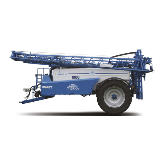
Page 17: Description Of The Machine
13 5-way valve 4 Tire/wheel 14 Filling pump 5 Chemical tank (Ecomixer) 15 Spray and pump manometers 6 Pump 16 Tank control 7 Drive 17 Side filling coupling 8 Ladder 9 Clean water tank 10 Container for washing hands www.agrio.cz info@agrio.cz... - Page 18 Fig. 5/2 Machine components – view from the right 1 Jack stand (mechanically released) 2 Boom lights 3 Storage space for equipment Fig. 5/3 Machine components – detail of tilt mechanism 1 Tilt motor 2 Tilt potentiometer 3 Tilt shaft (helix) 4 Tilt gears www.agrio.cz info@agrio.cz...
- Page 19 Fig. 5/4 Machine components – view from the rear 1 Tower 6 Boom extension piston 2 Carriage 7 Air pistol 3 Swing 8 Wheel chocks 4 Air reservoir 9 Tail lights 5 Piston lift 10 Warning triangle www.agrio.cz info@agrio.cz...
- Page 20 4 Control valve 11 Pressure inlet from 5-way valve 5 Sectional valve 12 Air chamber 6 Main valve (Boom) 13 Rinsing nozzles 7 Energy chain Note that the components may vary depending on the equipment of the machine! www.agrio.cz info@agrio.cz...
-
Page 21: Nameplate
The nameplate and stamped numbers are located on the front right side of the frame. Fig. 5/6 Parts of the nameplate 1 Machine type 2 Serial number 3 Curb weight (kg) 4 Total weight (kg) 5 Manufacture year www.agrio.cz info@agrio.cz... -
Page 22: Description Of Controls
25 Second hydraulic mixing Notes: *1 only in conjunction with hydraulic valve. *2 during automatic regulation, the computer takes over the regulation. *3 the switch is active only when the switch (11) is set to manual. Fig. 6/1 Control panel components www.agrio.cz info@agrio.cz... -
Page 23: Control Panels And Computers
6.1.1 Control panels and computers Comfort Terminal Navigation Track Guide II Spraydos Computer LH 4000 www.agrio.cz info@agrio.cz... - Page 24 Touch1200 Navigation Track Guide III StopSpray StopSpray connection diagram Stop-Spray connection diagram www.agrio.cz info@agrio.cz...
- Page 25 D-GPS Signal receiver Control box 12V Power supply Joystick Track Guide II Jobrechner Battery pack www.agrio.cz info@agrio.cz...
-
Page 26: Variations Of Computers And Panels Available
Tractor Jobrechner with box, without sensors. Cable to the ISOBUS plug: length 0.5 m Additional S-Box to Joystick (control panel max. 13 sections) StopSpray + Track Guide II Each type of computer or control panel comes with a detailed instruction manual that should be read carefully. www.agrio.cz info@agrio.cz... -
Page 27: Controls Of Sprayers Mamut 4000, 5000, 6000, 6500 And Mamut Xl
11 External filling and suction 12 Ecomixer valve 13 Pressure filters (sludge drain) 14 Clean water valve 15 Suction filter drain 16 External filling with 2“ check valve The layout may change according to the customer's wishes. Changes reserved. www.agrio.cz info@agrio.cz... -
Page 28: Controls For Sprayer Without Filling Pump
9 Clean water canister 10 Ecomixer rinsing pistol 11 External filling and suction 12 External filling with 2“ check valve 13 Pressure filter 14 Clean water valve The layout may change according to the customer's wishes. Changes reserved. www.agrio.cz info@agrio.cz... -
Page 29: Controls For Topline Type Sprayer
7 Independent external filler 8 External filling and suction 9 Clean water valve 10 Pressure filter (sludge drain) 11 Clean water canister 12 Ecomixer control valves 13 Rinsing pistol The layout may change according to the customer's wishes. Changes reserved. www.agrio.cz info@agrio.cz... -
Page 30: Description Of Topline Control Box Functions
16 Rinsing pistol This control box is supplemented with another smaller box, located in the cab, and used for switching the controls between inside the cab or from outside. The design may vary based on customer's request. Changes reserved. www.agrio.cz info@agrio.cz... -
Page 31: Description Of Function Of The Five-Way Valve
6.2.5 Description of function of the five-way valve Fig. 6/6 Description of the 5-way valve 1 Spray 2 Injector (Ecomixer) 3 Main tank mix 4 Main tank rinse www.agrio.cz info@agrio.cz... -
Page 32: General Description Of Functions
The chemical concentrate can be pumped into the main tank from the ground using the Ecomixer. Rinsing allows for the powder preparations to be dissolved and drained, and the Ecomixer wall can be washed. Moreover, the Ecomixer also contains a canister concentrate flushing device with a rotating rinsing nozzle. www.agrio.cz info@agrio.cz... -
Page 33: Mixing
Opening the drain valve from the main tank drains all the flushing water. The sprayer may be equipped with a high-pressure pistol which can be used to wash the sprayer from outside.. Attention! This operation must be performed in a location to prevent environmental risk. www.agrio.cz info@agrio.cz... -
Page 34: Operation
Must not touch the other parts of the machine. Securing against accidental motion: On a flat surface: with hand brake or wheel chocks. On a strongly sloping surface: with both hand brake and wheel chocks. Backing the tractor up to the sprayer tow hitch: www.agrio.cz info@agrio.cz... - Page 35 - Remove the wheel chocks from in front of (or behind) the wheels and attach them to the chock brackets. Platform ladder: - Raise the platform latter to the up position. General precautions: - Drain the air reservoir and sediment filter daily before each ride. www.agrio.cz info@agrio.cz...
-
Page 36: Disconnecting
Attention! Always secure the jack with the pin. For hydraulic jack legs, always place the red safety lock as shown in the picture, in case of damage to hydraulic lines! 8.3 Driving the connected sprayer www.agrio.cz info@agrio.cz... -
Page 37: Using The Brake System For The First Time
Inspections after each ride The operator must: after each ride, check whether the brake drums and wheel hubs are not overheated. stop the operation if a defect on the machine endangers his safety. 8.3.4 Hauling the sprayer Attention! www.agrio.cz info@agrio.cz... -
Page 38: Preparing For Application
Be careful when using the size 80 and 100 mesh to ensure that solids do not get stuck on the mesh. Before changing the preparation, the sprayer should be thoroughly rinsed. Flush the distribution system: - each time you change the nozzles. - before you insert other nozzles. - before turning a multi-nozzle holder to another nozzle.. www.agrio.cz info@agrio.cz... -
Page 39: Filling The Main Tank
Turn the 5-way valve to "Ecomixer". Turn on the piston diaphragm pump. Set the working pressure gauge to 6-8 bar. Attention! Do not exceed the maximum permitted pump RPM of 540! After reaching the desired fill of the tank, turn off the pump. www.agrio.cz info@agrio.cz... -
Page 40: Filling The Sprayer Tank From The Outside
Attention! First shut off the inlet to the hydraulics and then remove the suction hose. Sucking air into the tank could cause foaming and overflow the tank. www.agrio.cz info@agrio.cz... -
Page 41: Filling The Sprayer Tank With The Tank-Stop Function
Fig. 9/1 Filling pump 1 Centrifugal pump 2 C-terminal 3 Quick connector valve 4 Tank drain 9.1.6 Filling the sprayer tank with the Tank-stop function Fig. 9/2 Filling with Tank-stop Equipment description: 1 Tank-stop. 2 Tank-Control. 3 Filling pump. www.agrio.cz info@agrio.cz... -
Page 42: Filling The Tank With Clean Water
Connect the tap water hose to the quick connector (1). Open the quick connector (2) and the tap water valves. Monitor the level of water entering the clean water tank. After reaching a sufficient filling amount, close the quick connector (2) and tap water valves. www.agrio.cz info@agrio.cz... -
Page 43: Filling With Pesticides Using The Ecomixer
When mixing pesticides, wear appropriate protective clothing to prescribed by the chemical manufacturer! When preparing the spray mix, there is a high risk that you will come into contact with chemicals! Attention! Never move away from Ecomixer when it is being used! www.agrio.cz info@agrio.cz... -
Page 44: Description Of Ecomixer Parts
1 Rinse frame. 1 Rinse frame valve 2 Canister rinse nozzle. 2 Mixing nozzle valve 3 Mesh 3 Rinse pistol valve 4 Mixing nozzle 5 Ecomixer control levers Ecomixer with EasyFlow For instructions, see the separate manual for the EasyFlow. www.agrio.cz info@agrio.cz... - Page 45 Description of tilting Ecomixer Fig. 9/6 Description of tilting Ecomixer 1 Ecomixer. www.agrio.cz info@agrio.cz...
-
Page 46: Adding Preparations Through The Ecomixer
Urea is dissolved under continuous pumping of liquid through the pump back to the tank. The dissolution of urea results in a strong cooling of the spray mix, which slows the dissolution process. The warmer the water used, the faster and better the urea dissolves. 9.3.4 Rinsing the Ecomixer www.agrio.cz info@agrio.cz... -
Page 47: Canister Rinse Nozzle
See (Fig. 6/2, 6/3) - The 5-way valve (7) must be set to mixer. - Switch on the pump (2). Mixing with dual hydraulic agitation while spraying. During spraying, the 5-way valve (7 Figure 6/2, 6/3) must be set to "spray". www.agrio.cz info@agrio.cz... -
Page 48: Applying The Spray Mix
Turn on the section valves (10 Figure 6/1) Turn on the main spray valve (9 Figure 6/1). Attention! The pump speed must not exceed 540 RPMs! The fluid pressure at the nozzle can be checked on the glycerin manometer on the rail platforms. www.agrio.cz info@agrio.cz... -
Page 49: With "Twin Flow" Individual Nozzle Switching Equipment
This activity must be carried out at least five times (switch on, off). This will prevent the formation of sediments that can reduce the quality of the spray. www.agrio.cz info@agrio.cz... -
Page 50: Cleaning And Rinsing
Reduce the engine speed (recommended shaft speed is about 250 RPM). Set the 5-way valve to "rinse tanks". Open the inlet for clean water. If the sprayer is equipped with dual mixing (25 Figure 6/1), it may be briefly turned on. www.agrio.cz info@agrio.cz... - Page 51 If the filters are fitted with drain valves, open the drain valve filter and capture the mix into the tank. - Sprayer booms: - Extend and run. - Tilt slightly. - At the lowest-lying nozzle for each section, loosen the drip-catch and capture the liquid into the tank. www.agrio.cz info@agrio.cz...
- Page 52 Turn the drain screw (1 Fig. 11/1) from the piston diaphragm pump. Fig. 11/1 Drain screws on the pump 1 Drain screw for spray. 2 Drain screw for oil. www.agrio.cz info@agrio.cz...
-
Page 53: Sensor Calibration
The actual ground speed. Dose (according to recommendations of product manufacturer) The flow rate is calculated using the following formula: Dose (l/ha) x actual speed (km/h) x nozzle distance (m) Flow rate at the nozzle = --------------------------------------------- ------------------------------- www.agrio.cz info@agrio.cz... -
Page 54: Setting The Correct Nozzle Pressure
The time required for this method is significantly longer. With a properly set spraying pressure, and by maintaining the given speed, the sprayer is able to spray the exact required dose. www.agrio.cz info@agrio.cz... -
Page 55: Booms
Regularly check the condition of the main cable and cables. If the cable fibers are damaged, the cable must be replaced immediately. If the cables break, the booms can be damaged! Attention! The maximum permissible speed of the sprayer with extended booms is 12 km/h! www.agrio.cz info@agrio.cz... -
Page 56: Precautions For Standard Boom Expansion
- Make sure that the booms are resting completely on the front and rear supports. Attention! Extend and fold the booms without interrupting the motion! The booms can be extended and folded only when the machine is at rest; otherwise this function is electronically locked. www.agrio.cz info@agrio.cz... -
Page 57: Securing The Booms
If the springs are not fitted, the sprayer copies the uneven terrain of the land to a minimal degree. Using the sprayer on slopes without the springs fitted is not recommended. www.agrio.cz info@agrio.cz... -
Page 58: Boom Suspension
In order to finely adjust the tilt angle, the tilt ratio of the potentiometer knob to the boom tilt is 1:8; this means that when the potentiometer knob is rotated by 1°, the boom tilts 8 mm in the same direction of the knob rotation. www.agrio.cz info@agrio.cz... -
Page 59: Automatically Tilting The Booms With The "Parallelomat" Contact Antennae (Optional Equipment)
(optional equipment) Operated the same way as without automatic boom lifting. Chapter. 13.4.4.1 Function. This additional function is activated when both antennas make contact with the ground or vegetation. The booms must be lowered manually, if necessary. www.agrio.cz info@agrio.cz... -
Page 60: Automatically Tilting "Distance - Control" Ultrasonic Sensor (Optional Equipment)
Sprayers equipped with hydraulic boom tilting with a 6-sectional electro-hydraulic distributor can also operate the booms up, down, extend, and fold. Control panel for hydraulic tilting: Fig. 13/2 Description of control panel for hydraulic tilting 1 Extend/fold the booms. 2 Lift/lower the booms. 3 Tilt the booms right/left. www.agrio.cz info@agrio.cz... -
Page 61: Booms - Types And Control
Booms of a durable and lightweight spatial construction, suspended by compression springs with a span of 15-36 meters, stabilized in both planes by telescopic shock absorbers. The suspension and tilt are designed to reliably keep the booms at the correct distance above the area of application. www.agrio.cz info@agrio.cz... -
Page 62: Booms 18-36M
The booms are extended and folded via chain sprockets and cranks in a single working run. Fig. 13/4 Extended booms 18 – 36m 1 Inner boom. 2 Middle boom. 3 Outer boom. 4 Chain rod. 5 Sprocket. 6 Antennae. 7 Outer boom shock. 8 Stop bushing. www.agrio.cz info@agrio.cz... -
Page 63: Combination Of Folding Booms
Manually removing the outer booms - Close the spray distribution valves and disconnect the removable parts of the booms. - Remove the outer booms. When removing the outer booms it is useful to support the opposite side of the booms. www.agrio.cz info@agrio.cz... -
Page 64: Folding And Unfolding The Central Booms
- Fold the outer booms to a shortened span. - Manually secure the booms with clips! Attention! Unsecured booms may be damaged! - Procedure for completely folding the booms: - Lift the booms into the upper position. - Unfold the booms to their entire working span. www.agrio.cz info@agrio.cz... -
Page 65: Axles
When using ET + -75 mm, the gauge may be 1500-2250 mm (for MAMUT sprayers the minimum gauge is 1800 mm 14.1.2 Axle description 1 Axle beam 2 Half-axle 3 Chassis mounting plate 4 Hand brake cable caliper www.agrio.cz info@agrio.cz... -
Page 66: Axle Maintenance
M 12 x 1.5 M 14 x 1.5 M 16 x 1.5 M 18 x 1.5 600mm M 20 x 1.5 600mm M 22 x 1.5 800mm M 22 x 2 M 24 x 1.5 14.1.3.2 Checking the brakes www.agrio.cz info@agrio.cz... - Page 67 Check the condition of the brake linings. When the lining is worn to a thickness less than 1 mm, replace the lining. Check the condition of the lubricant in the bearings of the wheel hubs (TUK AK 2). Grease the lubrication points (TUK A00). After each 60,000 km or once per year. www.agrio.cz info@agrio.cz...
-
Page 68: Bpw Air Suspension Axle
These axles differ from each other mostly in the size of the bellows. Attention! The sprayer may be set into motion only when both air bellows are filled completely with air and the desired height setting is reached; otherwise the bushings can be destroyed. www.agrio.cz info@agrio.cz... -
Page 69: Axle Specifications
The brakes are drum brakes with internal calipers. Brake pads are attached to the brake calipers. The brake calipers are controlled by brake keys with a cam. The brake keys are stored in the bearings of the brake keys that are welded to the axle beam. Brake levers are www.agrio.cz info@agrio.cz... -
Page 70: Axle Maintenance
Check the tightness of the bolts of M30….M=900Nm attaching the hinge spring Check the shock absorber bolts M24….M=420Nm M12….M=66Nm Check the bolts of the air bellows M16….M=230Nm For inspection of the hubs and brake system, see Maintenance of BPW fixed axles. www.agrio.cz info@agrio.cz... -
Page 71: Additional Equipment
(dosage table of different manufacturers). the nozzle is properly set in the seal. all connections are tight. 15.2 Sprayer navigation during application 15.2.1 Foam marker 1 Foamer container 2 Cover 3 Locking clip 4 Insertion pin 5 Air check valve www.agrio.cz info@agrio.cz... -
Page 72: Satellite Navigation System
Fig. 15/2 Description of the sprayer external washer 1 Reel with hose 2 Valve 3 High pressure pistol 4 5-way valve 5 Valve for Ecomixer and drum 6 Brush 7 Valve for adding clean water and washing the outside www.agrio.cz info@agrio.cz... -
Page 73: External Washing Without Pressure From A Fresh Water Tank
If the drawbar is to be turned in the field, the hydraulic fuse must first be unlocked. To do so, turn the lever (Figure 15/3) 90° all the way, thus securing the locking pin back. Turns are made by operating the corresponding hydraulic function. The drawbar turns smoothly without jerking. www.agrio.cz info@agrio.cz... -
Page 74: Automatically Swiveling The Drawbar (Trail-Control)
For more details, refer to the instruction manual for "Trail - control" Attention! The swiveling drawbar function must be switched off when driving on public roads. Fig. 15/3 Electrical regulation of the swiveling drawbar www.agrio.cz info@agrio.cz... -
Page 75: Filling Aerial Filter
The filter is composed of three basic parts – the outer case, the cover, and the filter itself (insert). Any parts of the filter that come into contact with the pumped liquid are protected against corrosion. Specifications Type: Stainless steel aerial filter Agrio 500 Volume: 18 l Weight: 4.5 Kg Diameter: ø... - Page 76 2 Case flange 3 Stainless steel filter lid 4 O-ring seal 5 2“ socket 6 Handle 7 Quick-release closure 8 Holders 9 Bottom of stainless steel case 10 Stainless steel removable insert Fig. 15/4 Description of the aerial filter www.agrio.cz info@agrio.cz...
-
Page 77: Maintaining And Caring For The Machine
Examine normal corrosion on the machine. Pay special attention to the brake, air and hydraulic lines. After cleaning, lubricate the sprayer, especially after washing with high-pressure equipment or steam or degreasing agents. Follow the rules for handling the detergents. Attention! Never treat the brake lines with petrol, benzene, petroleum or mineral oil! www.agrio.cz info@agrio.cz... -
Page 78: Cleaning With High-Pressure Cleaner / Steam Cleaner
Disconnect hoses from the glycerin pressure gauges (working and spray). Follow these steps: - Wash the machine completely. - Drain the air system. - If the pump is driven by V-belts, they must be loosened. Clean the corroded parts and repaint them. www.agrio.cz info@agrio.cz... -
Page 79: Spray Pump
9 M8 screw 10 Elbow 11 Seal 12 Plug Fig. 16/2 Description of the pump – housing 1 Upper air chamber 2 Diaphragm 3 Lower chamber 4 O-ring ø29x3 5 M8 nut 6 M8 screw 7 Seal 8 Air valve www.agrio.cz info@agrio.cz... -
Page 80: Checking The Oil Level
Maintain an accurate oil level. Too much or too little oil is harmful. Oil level. Check that the oil level of the standing pump is visible (Figure 16/7); the sprayer must be in a horizontal position. If the oil level is low, remove the cap and add oil. www.agrio.cz info@agrio.cz... -
Page 81: Changing The Oil
Turn the shaft (9) by hand until the old oil has drained completely. There will still be remnants of the old oil in the pump. The manufacturer recommends that the pump be removed from the chassis and that the glass be turned upside down. www.agrio.cz info@agrio.cz... -
Page 82: Air Pressure In The Pump
Belts of the pump's mechanical drive. - Test force Fe= 75N. - For pump speed 540/min. - Maximum allowable deflection = 14mm. If the maximum deflection is exceeded, the pump will loosen at the tension bolt on the base plate. www.agrio.cz info@agrio.cz... -
Page 83: Changing The V-Belt
Turn the shaft so that the piston of the test or exchanged diaphragm is on top so that the oil leaks from the housing. Always replace all diaphragms even if only one is damaged or worn. www.agrio.cz info@agrio.cz... -
Page 84: Summary Of Key Points
Each time you fill the tank, check the entire suction path to prevent blockage to the pump inlet. Symptoms of diaphragm rupture include loss of oil from the pump or formation of emulsion in the expansion tank - immediately shut down the machine and fix the pump. www.agrio.cz info@agrio.cz... -
Page 85: Calibrating The Flow Meter
- after prolonged use, because chemical residues can accumulate in the flowmeter - when a difference arises between the actual and calculated applied amount Calibrate the flowmeter separately for water and DAM 390 Calibrate the meter according to the instructions of the a particular type of computer. www.agrio.cz info@agrio.cz... -
Page 86: Oiling Scheme
Pulleys of the main cable of the Liquid lubricant master cylinder *30 Upper swing joint Liquid lubricant Rod holder joint Universal grease Crank joint Universal grease Lower swing joint Liquid lubricant Rod spring eye Liquid lubricant Rod chain Universal grease www.agrio.cz info@agrio.cz... - Page 87 * If your sprayer is a version without a grease nipple, use a graphite lubricant spray - recommended sprays are HIGH-BLACK PRESS from the manufacturer NORMFEST. Lubrication sites: Chassis: www.agrio.cz info@agrio.cz...
- Page 88 info@agrio.cz...
- Page 89 info@agrio.cz...
- Page 90 info@agrio.cz...
- Page 91 info@agrio.cz...
- Page 92 Booms: www.agrio.cz info@agrio.cz...
- Page 93 info@agrio.cz...
- Page 94 info@agrio.cz...
- Page 95 info@agrio.cz...
- Page 96 info@agrio.cz...
-
Page 97: Overview Of Maintenance
Check the brake linings Min cable Check cable for wear Flowmeter Flowmeter calibration Nozzles Replace worn out nozzles Check for lateral uniformity – subject to regular checkup at an officially authorized station. This check is carried out every 3 years. www.agrio.cz info@agrio.cz... -
Page 98: Troubleshooting Assistance
Check the manometer on the If the air manometer on the control panel and manometer control panel and working working manometer on the manometer shows no pressure, sprayer. proceed according to 1/a, 1/b, 1/c, 1/e, 1/f, 1/g www.agrio.cz info@agrio.cz... - Page 99 Incorrectly selected nozzles. Small dose for a large nozzle. Travel speed too slow. Dosages not achieved Error in regulation air pressure. Air leak between control panel and regulation valve (in the control panel, air quick connector of control panel, in www.agrio.cz info@agrio.cz...
- Page 100 Defective potentiometer in the tower. Defective circuit board for tilting in the control panel. Tilt hydraulics not functioning. Improper alignment of the hydraulic circuit on the tractor. Blocked tilt limiter at the tilting hydraulic piston. Improperly set controls for the www.agrio.cz info@agrio.cz...
- Page 101 Problems when swiveling the Problems when swiveling the Hoses to the hydraulic circuit of drawbar. drawbar. the tractor are Improperly connected. Sensors Improperly aligned. Hydraulic regulators to the drawbar pistons Improperly aligned. Too high travel speed. www.agrio.cz info@agrio.cz...
-
Page 102: Appendices
Brakes lock up. Defect in the tractor's brake system. Improperly configured load regulator. Improperly set key with brake cylinder lever. Faulty air reservoir caliper. Faulty air release valve for brake cylinders. 20 APPENDICES 20.1 Hydraulic diagram of the sprayer www.agrio.cz info@agrio.cz... - Page 103 Attention: diagrams will vary depending on the machine's equipment! www.agrio.cz info@agrio.cz...
- Page 104 LENGTH ADD. DIMENSION MATERIAL MASS DEV.NO – NORM POS. NOTE: TOTAL WEIGHT: 104.19 Kg WH CODE 2: WH CODE: SCALE DRAWN TESTED BY APPROVED BY TECHN. DATE GROUP: FOLDER NAME HYDRAULIC DIAGRAM CHANGE DATE (NEČITELNÝ) INDEX FILE DRAWING nO. PAGES PAGE www.agrio.cz info@agrio.cz...
-
Page 105: Sprayer Brake Diagram
20.2 Sprayer brake diagram www.agrio.cz info@agrio.cz... - Page 106 DOUBLE VALVE TRISTOP BRAKE RELEASE SPRING VALVE RELEASE VALVE 6 BAR RIGHT BELLOWS LEFT BELLOWS FILTER (RED) TERMINAL AIR RESERVOIR 40L QUICK AIR RELEASE TRISTOP VALVE HAND BRAKE LOAD REGULATOR TRAILER DISTRIBUTOR TRISTOP SPRING VALVE www.agrio.cz info@agrio.cz...
-
Page 107: Wiring Diagram
20.3 Wiring diagram www.agrio.cz info@agrio.cz... - Page 108 LH + CONTROL BOX FUSE BOX II (BENEATH STEPS) MOTOR ELECTRIC MOTOR FLOWMETER TRAVEL SENSOR TERMINAL SWITCH POTENTIOMETER AMPHENOL – VIEW SEVEN-PIN PLUG RIGHT BLINKER LEFT BLINKER OUTLINE BRAKE BOX I. TRANSPORT LIGHTS LEFT COMBINED LIGHT RIGHT COMBINED LIGHT www.agrio.cz info@agrio.cz...
-
Page 109: Hydraulic Connection Operation Diagram
20.4 Hydraulic connection operation diagram: www.agrio.cz info@agrio.cz... - Page 110 MAIN VALVE 1. SECTION (2. SECTION, 3. SECTION, ATD…) MAIN AIR SUPPLY REGULATION VALVE BOOMS-UP/DOWN BOOMS-EXTEND/FOLD AIR QUICK CONNECTOR – VIEW LEGEND: SECTION VALVE MAIN VALVE REGULATION VALVE MAIN AIR SUPPLY AIR RELEASE VALVE BOOM control "T" PIECE www.agrio.cz info@agrio.cz...
-
Page 111: Mamut Technical Diagram
20.5 MAMUT technical diagram www.agrio.cz info@agrio.cz... - Page 112 TOPLINE WATER DIAGRAM (BASIC) MAIN MIXING RINSE NOZZLE INJECTOR CANISTER RINSE NOZZLE 2-LEVER VALVE ECOMIXER MIXING ECOMIXER RINSE FRAME REGULATION VALVE MAIN VALVE SECTION VALVE PRESSURE FILTER FLOWMETER BOOMS TANK DRAIN PISTON CONTROLLED 2-WAY VALVE DRAIN VALVE WITH GEKA CONNECTOR www.agrio.cz info@agrio.cz...
-
Page 113: Dosage Tables
DT 2.0 blue 1.06 0,85 DT 2.5 brown white 1.33 1.02 1.32 DT 3.0 grey white 1.36 1.76 DT 4.0 white white 2.12 DT 5.0 without light mesh 2.66 blue Nozzle distance 50cm, pressure measured before stop-drip valve. www.agrio.cz info@agrio.cz... - Page 114 0.86 1.5/59 1.38 1.22 1.69 1.49 1.38 1.22 1.8/72 1.96 1.73 2.12 Working pressure = 1.0-5.0 bar. Black nozzles are combined with dosage coins with opening 0.8-1.2 mm. Grey nozzles are designed for dosage coins of 12-1.8 mm. www.agrio.cz info@agrio.cz...
- Page 115 Nozzle color. l/min Pressure (bar) yellow green blue white grey black 0.44 0.74 0,82 1.04 1.56 2.61 3.31 0,83 0,93 1.18 1.78 2.93 3.79 0,56 1.02 1.98 3.21 4.22 0,61 0,97 2.15 3.45 0,65 1.03 1.18 1.49 2.31 3.67 4.95 www.agrio.cz info@agrio.cz...
- Page 116 110-15 80-15 5.477 1643 1314 1095 Pink 1800 1440 1200 1029 Without filter 6.928 2078 1663 1386 1188 1039 5.657 1697 1358 1131 110-20 80-20 6.532 1960 1568 1306 1120 Light blue 7,303 2191 1753 1461 1252 1095 www.agrio.cz info@agrio.cz...
- Page 117 0,816 1663 AirMix 0,913 110-025 purple 1.154 1.291 1.414 0,693 0,849 0,98 AirMix 1.095 110-03 blue 1.386 1.549 1.697 0,924 1.131 1.306 AirMix 1.461 110-04 1.848 2.066 2.263 1.155 1.414 1.633 AirMix 1.826 110-05 brown 2.309 2.582 2.828 www.agrio.cz info@agrio.cz...
- Page 118 1960 2078 2191 1155 1633 2000 2309 2582 TD05 brown 2828 3055 3264 3464 6351 1848 2613 3200 3694 4132 TD08 white 4526 1084 4888 1172 5224 1252 1044 5542 1328 1108 5842 1400 1168 1000 TD015 green www.agrio.cz info@agrio.cz...
- Page 119 +/- 5%. Pressure loss between the manometer and nozzle is not taken into account. When applying liquid fertilizer DAM-390, the values are reduced by 13%. Optimum pressure for plant protection: TD atm 4-8, 2-4 atm TDXL www.agrio.cz info@agrio.cz...
- Page 120 For the application of midsize and small drops: TD min. 6 atm, TDXL min. 4 atm Optimum pressure for liquid fertilizers: TD 2-3 atm, TDXL 1-2 atm Usable range of pressures: TD 4-10 atm (standard), 4-20 atm (universal), TDXL 1-8 atm Recommended height above the target area: 60-100cm, optimum 70cm. www.agrio.cz info@agrio.cz...
Need help?
Do you have a question about the Mamut 6500 and is the answer not in the manual?
Questions and answers