Table of Contents
Advertisement
Advertisement
Table of Contents

Related Manuals for Hantek HDG6112B


Summarization of Contents
Safety Terms and Symbols
Terms on the product
Defines terms like Danger, Warning, Notice used in the manual.
Characters on the product
Explains symbols found on the product for safety and grounding.
Chapter 1 Quick Start
General Inspection
Outlines checks for shipping damage, accessories, and instrument condition upon receipt.
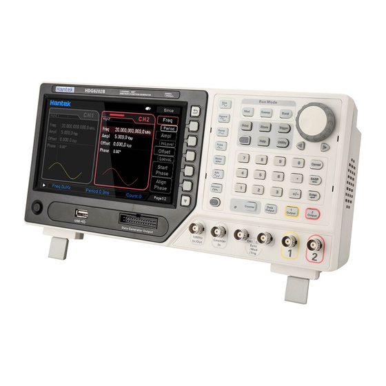
Front Panel
Describes the components and layout of the instrument's front panel for user familiarity.
Rear Panel
Details the connectors and ports available on the rear of the instrument.
Prepare Instrument for Use
Guides users on setting up the instrument, including adjusting legs and connecting power.
The user interface
Explains the different regions of the instrument's display screen and their functions.
Parameter Setting Method
Covers methods for setting parameters using the numeric keyboard, direction keys, and knob.
Chapter 2 Basic Waveform Output
Select the channel
Describes how to choose between CH1, CH2, or dual-channel output for waveform generation.
Setting the parameter
Details the process of configuring parameters for basic waveforms, including frequency, amplitude, and offset.
Basic Waveform Output Example
Provides a step-by-step example for outputting a pulse waveform with specific parameters.
Chapter 3 Arbitrary Waveform Output
Enable Arbitrary Waveform
Explains how to activate the arbitrary waveform function and set its basic parameters.
Select Arbitrary Waveform
Details how to choose from the extensive library of built-in arbitrary waveforms.
Chapter 4 Harmonic Output
Overview
Explains the concept of harmonic generation based on Fourier transform and instrument capabilities.
Set the Fundamental Waveform Parameters
Describes setting parameters like frequency, amplitude, and phase for the fundamental waveform.
Set the Harmonic Order
Details how to specify the highest order of harmonic to be generated, up to the 16th order.
Select the Harmonic Type
Covers selecting between even, odd, or all harmonic types for output.
Set the Harmonic Amplitude
Explains how to set the amplitude for each specified harmonic order.
Set the Harmonic Phase
Details how to set the phase for each specified harmonic order.
Chapter 5 Modulated Waveform
AM Modulation
Explains Amplitude Modulation, including carrier shape, frequency, source, and depth settings.
DSB-AM Modulation
Details Double-Sideband Amplitude Modulation, covering carrier and modulating waveform parameters.
FM Modulation
Describes Frequency Modulation, including carrier shape, frequency, source, and deviation settings.
PM Modulation
Explains Phase Modulation, covering carrier shape, frequency, source, and phase deviation settings.
2ASK
Details 2-Amplitude Shift Keying modulation, covering carrier shape, amplitude, source, and rate settings.
2FSK
Explains 2-Frequency Shift Keying modulation, including carrier shape, frequency, source, rate, and hopping frequency settings.
2PSK
Covers 2-Phase Shift Keying modulation, including carrier shape, phase, source, and rate settings.
BPSK
Details Binary Phase Shift Keying modulation, including carrier shape, phase, source, and rate settings.
QPSK Modulation
Explains Quadrature Phase Shift Keying, covering carrier shape, phase, source, and rate settings.
3FSK Modulation
Covers 3-Frequency Shift Keying, including carrier shape, frequency, source, and rate settings.
4FSK Modulation
Explains 4-Frequency Shift Keying, including carrier shape, frequency, source, and rate settings.
OSK Modulation
Details Oscillation Shift Keying modulation, covering carrier shape, frequency, source, and rate settings.
PWM Modulation
Explains Pulse Width Modulation, including carrier shape, duty cycle, source, and deviation settings.
Chapter 6 Sweep
Select Frequency Sweep
How to enable the frequency sweep function and its basic settings.
Start Frequency and Stop Frequency
Setting the upper and lower frequency limits for the sweep.
Center Frequency and Frequency Span
Alternative method to define sweep boundaries using center frequency and span.
Linear sweep
Describes the linear sweep type and its control parameters.
Sweep Time
Setting the duration for the frequency sweep.
Return Time
Specifies the time to return from stop to start frequency after a sweep.
Hold Time
Setting the duration the sweep stays at the stop frequency.
Mark Frequency
Defines a frequency point for triggering or synchronization during a sweep.
Sweep Trigger Source
Selecting the source for triggering the sweep operation (Internal, External, Manual).
Trigger Output Edge
Configuring the edge (rising/falling) of the trigger output signal.
Chapter 7 Burst
Select Burst Mode
How to enable and configure the burst mode of operation.
Burst Type
Describes the three burst types: N Cycle, Infinite Cycle, and Gated.
Burst Period
Setting the time between the start of successive bursts for N Cycle mode.
Burst Phase
Defining the starting phase of the burst waveform.
Burst Trigger Source
Selecting the source to trigger the burst output (Internal, External, Manual).
Gate Polarity
Setting the polarity (positive/negative) for gated burst mode.
Trigger Output Edge
Configuring the edge of the trigger output signal in burst mode.
Chapter 8 Counter
Enable the Counter
Steps to activate the counter function and prepare for measurement.
Set the Counter
Configuring counter parameters like gate time, sensitivity, and trigger level.
Chapter 9 Digital Generator
Terminal Description
Describes the terminals used for the digital generator function.
Function Introduction
Explains how to use the digital generator for sync signals or programmable digital patterns.
Chapter 10 Utility
Sync
Explains the synchronization signals and their behavior for various output modes.
Impedance
Setting the output impedance (50Ω or HighZ) and its effect on amplitude.
Network for HDG6000C
Configuration of network interfaces (LAN, WLAN, Hotspot) for remote communication.
System Setting
Settings related to system language, power-on behavior, sound, and screen intensity.
Print
How to print the screen or save screenshots to a USB device.
Update
Procedure for updating the instrument's firmware.
Store and Recall
Saving and loading instrument states, waveforms, and settings.
Chapter 11 Remote Control
Install Keysight IO libraries suite
Step-by-step guide to installing the necessary software for remote control.
Remote Control via USB
Connecting and controlling the instrument via USB interface.
Remote Control via LAN (HDG6000C)
Connecting and controlling the instrument via LAN interface.
Remote Control via WLAN (HDG6000C)
Connecting and controlling the instrument via WLAN interface.
Remote Control via Hotspot (HDG6000C)
Connecting and controlling the instrument via its built-in hotspot.
Need help?
Do you have a question about the HDG6112B and is the answer not in the manual?
Questions and answers