Sign In
Upload
Download
Table of Contents
Contents
Add to my manuals
Delete from my manuals
Share
URL of this page:
HTML Link:
Bookmark this page
Add
Manual will be automatically added to "My Manuals"
Print this page
×
Bookmark added
×
Added to my manuals
Manuals
Brands
Hantek Manuals
Pulse Generator
HDG6000B Series
User manual
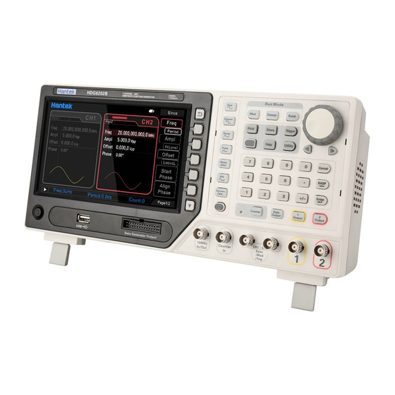
Hantek HDG6000B Series User Manual
Functions and arbitrary waveform generator
Hide thumbs
1
Table Of Contents
2
3
4
5
6
7
8
9
10
11
12
13
14
15
16
17
18
19
20
21
22
23
24
25
26
27
28
29
30
31
32
33
34
35
36
37
38
39
40
41
42
43
44
45
46
47
48
49
50
51
52
53
54
55
56
57
58
59
60
61
62
63
64
65
66
67
68
69
70
71
72
73
74
75
76
77
78
79
80
81
82
83
84
85
86
87
88
89
90
91
92
93
94
95
96
97
98
99
100
101
102
103
104
105
106
107
page
of
107
Go
/
107
Contents
Table of Contents
Bookmarks
Table of Contents
Table of Contents
Copyright Declaration
General Safety Summary
Safety Requirements
Product Scrapping
Safety Terms and Symbols
Brief Introduction
Chapter 1 Quick Start
General Inspection
Front Panel
Rear Panel
Prepare Instrument for Use
The User Interface
Parameter Setting Method
Numeric Keyboard
Direction Keys and Knob
Help
Chapter 2 Basic Waveform Output
Select the Channel
Setting the Parameter
Select the Basic Waveform
Set the Frequency
Set the Amplitude
Set the DC Offset Voltage
Set the Start Phase
Align Phase
Set the Duty Cycle
Set the Symmetry
Set the Pulse Parameters
Enable the Channel Output
Basic Waveform Output Example
Chapter 3 Arbitrary Waveform Output
Enable Arbitrary Waveform
Select Arbitrary Waveform
Chapter 4 Harmonic Output
Overview
Set the Fundamental Waveform Parameters
Set the Harmonic Order
Select the Harmonic Type
Set the Harmonic Amplitude
Set the Harmonic Phase
Chapter 5 Modulated Waveform
AM Modulation
Select am Modulation
Carrier Waveform Shape
Carrier Frequency
Modulating Waveform Source
Modulating Waveform Frequency
Modulation Depth
DSB-AM Modulation
Select DSB-AM Modulation
Carrier Waveform Shape
Carrier Frequency
Modulating Waveform Source
Modulating Waveform Frequency
Modulation Depth
FM Modulation
Select FM Modulation
Carrier Waveform Shape
Carrier Frequency
Modulating Waveform Source
Modulating Waveform Frequency
Frequency Deviation
PM Modulation
Select Phase Modulation
Carrier Waveform Shape
Carrier Frequency
Modulating Waveform Source
Modulating Waveform Frequency
Phase Deviation
2Ask
Select 2ASK Modulation
Carrier Waveform Shape
Carrier Amplitude
Modulating Waveform Source
2ASK Rate
Modulating Amplitude
2Fsk
Select 2FSK Modulation
Carrier Waveform Shape
Carrier Frequency
Modulating Waveform Source
2FSK Rate
Hopping Frequency
2Psk
Select 2PSK Modulation
Carrier Waveform Shape
Carrier Phase
Modulating Waveform Source
2PSK Rate
Modulating Phase
Bpsk
Select BPSK Modulation
Carrier Waveform Shape
Carrier Phase
Modulating Waveform Source
BPSK Rate
Modulating Phase
QPSK Modulation
Select QPSK Modulation
Carrier Waveform Shape
Carrier Phase
Modulating Waveform Source
QPSK Rate
Modulating Phase
3FSK Modulation
Select 3FSK Modulation
Carrier Waveform Shape
Carrier Frequency
Modulating Waveform Source
3FSK Rate
Hopping Frequency
4FSK Modulation
Select 4FSK Modulation
Carrier Waveform Shape
Carrier Frequency
Modulating Waveform Source
4FSK Rate
Hopping Frequency
OSK Modulation
Select OSK Modulation
Carrier Waveform Shape
Carrier Frequency
Modulating Waveform Source
OSK Rate
Oscillate Period
Pwm
Select PWM Modulation
Carrier Waveform Shape
Duty Cycle
Modulating Waveform Source
Modulating Waveform Frequency
PWM Deviation
Chapter 6 Sweep
Select Frequency Sweep
Start Frequency and Stop Frequency
Center Frequency and Frequency Span
Linear Sweep
Sweep Time
Return Time
Hold Time
Mark Frequency
Sweep Trigger Source
Trigger Output Edge
Chapter 7 Burst
Select Burst Mode
Burst Type
Burst Period
Burst Phase
Burst Trigger Source
Gate Polarity
Trigger Output Edge
Chapter 8 Counter
Enable the Counter
Set the Counter
Chapter 9 Digital Generator
Terminal Description
Function Introduction
Chapter 10 Utility
Sync
Impedance
Network for HDG6000C
LAN Setting
WLAN Setting
Hotspot
System Setting
Set the System Language
Power on Setting
Sound
Intensity
System Information
Clock Source
Print
Update
Store and Recall
Storage System Overview
Browser Type
File Operation
Chapter 11 Remote Control
Install Keysight IO Libraries Suite
Remote Control Via USB
Remote Control Via LAN (HDG6000C)
Remote Control Via WLAN (HDG6000C)
Remote Control Via Hotspot (HDG6000C)
Appendix A Specifications
Appendix B Accessories
Advertisement
Quick Links
1
Table of Contents
2
Appendix A Specifications
Download this manual
HDG6000B(C) series
Functions and Arbitrary Waveform
Generator
User manual
(V1.2)
Table of
Contents
Previous
Page
Next
Page
1
2
3
4
5
Advertisement
Table of Contents
Need help?
Do you have a question about the HDG6000B Series and is the answer not in the manual?
Ask a question
Questions and answers
Related Manuals for Hantek HDG6000B Series
Pulse Generator Hantek HDG6082B User Manual
Functions and arbitrary waveform generator (107 pages)
Pulse Generator Hantek HDG6112B User Manual
Functions and arbitrary waveform generator (107 pages)
Pulse Generator Hantek HDG6162B User Manual
Functions and arbitrary waveform generator (107 pages)
Pulse Generator Hantek HDG6202B User Manual
Functions and arbitrary waveform generator (107 pages)
This manual is also suitable for:
Hdg6000c series
Hdg6082b
Hdg6112b
Hdg6162b
Hdg6202b
Hdg6082c
...
Show all
Hdg6112c
Hdg6162c
Hdg6202c
Table of Contents
Print
Rename the bookmark
Delete bookmark?
Delete from my manuals?
Login
Sign In
OR
Sign in with Facebook
Sign in with Google
Upload manual
Upload from disk
Upload from URL


Need help?
Do you have a question about the HDG6000B Series and is the answer not in the manual?
Questions and answers