Advertisement

AIR CONDITIONER (MULTI TYPE)
Installation Manual
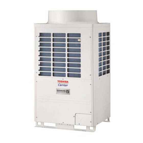
Outdoor Unit
Model name:
<Heat Recovery Model>
MMY-MAP0726FT9P-UL
MMY-MAP0966FT9P-UL
MMY-MAP1206FT9P-UL
MMY-MAP1446FT9P-UL
MMY-MAP1686FT9P-UL
For OUTDOOR USE only
Pour une UTILISATION EN EXTÉRIEUR
uniquement
1122001101
Installation Manual
1
English
Manuel d'installation
32
Français

Advertisement

Table of Contents
loading
Need help?

Need help?

Do you have a question about the Carrier MMY-MAP1446FT9P-UL and is the answer not in the manual?

Questions and answers

Summarization of Contents

Precautions for Safety
General Safety Guidelines
Essential safety practices for installation and operation.
Installation Location Selection
Choosing a suitable and safe place for the unit.
Installation and Wiring Safety
Safe procedures for installing the unit and electrical wiring.
Refrigerant Handling Safety
Precautions when working with refrigerant and piping.
Test Run and User Explanation
Safety during test runs and user guidance.
Unit Relocation Safety
Safety measures for relocating the air conditioner.
Accessory Parts Identification
Owner's Manual Inclusion
Confirmation that the owner's manual is included.
Installation Manual Inclusion
Confirmation that the installation manual is included.
R410A Air Conditioner Installation
Required Tools and Handling Cautions
Essential tools and safety notes for R410A installation.
Installation Place Selection
Installation Site Requirements
Conditions for ideal installation locations.
Unsuitable Installation Locations
Places to avoid for proper unit operation and safety.
Required Installation Space
Necessary clearances around the unit for maintenance.
Outdoor Unit Transportation
Handling Precautions
Essential safety measures when moving the outdoor unit.
Weight and Center of Gravity
Specifications for unit weight and its center of mass.
Outdoor Unit Installation
Secure Installation Warning
Critical safety warning about unit stability.
Foundation and Drainage Precautions
Ensuring a stable foundation and proper drainage.
Snowfall Area Installation Requirements
Specific installation steps for snowy regions.
Anchor Bolt and Vibration-Proofing
Proper installation of anchor bolts and vibration rubbers.
Unit Arrangement Guidelines
How to position multiple outdoor units.
Piping Diagrams and Guidelines
Discharge and Liquid Piping
Correct and incorrect diagrams for gas/liquid piping.
Suction Gas Piping
Correct and incorrect methods for suction gas piping.
Downward Pipe Drawing
Correct and incorrect methods for drawing pipes downwards.
Level Pipe Connection
Ensuring pipes are installed horizontally.
Refrigerant Piping Procedures
Refrigerant Leakage Warning
Cautionary note regarding potential refrigerant leaks.
Brazing and Piping Work Requirements
Essential steps for proper pipe connection.
Refrigerant Pipe Connection Steps
Detailed instructions for connecting refrigerant pipes.
Pipe Connection Examples
Visual guides for various pipe connection methods.
Copper Pipe Machining Specifications
Flare Machining Dimensions
Extruding margins for flare machining.
Brazed Pipe Coupling Sizes
Dimensions for brazed pipe couplings.
Pipe Size Selection Guide
Capacity Codes for Units
Table mapping unit capacity to codes.
Pipe Material Selection
Guidance on choosing the right pipe material.
Capacity Code Tables
Table 1: Indoor Unit Capacity Codes
Numerical equivalents for indoor unit capacities.
Connecting Pipe Specifications
Outdoor Unit Connection Pipes
Pipe sizes for connecting outdoor to indoor units.
Inter-Outdoor Unit Connection Pipes
Pipe sizes for connecting outdoor units together.
Main, Branching, and FS Unit Piping
Pipe sizes for main, branch, FS, and indoor connections.
Accessory Piping Component Models
Model numbers for Y-joints, headers, kits, and selectors.
Pipe Temper and Size Compliance
Pipe Temper Specifications
Table detailing pipe temper requirements by size.
System Operational Restrictions
Maximum Unit Combinations
Limits on connected outdoor and indoor units.
Installation Cautions Summary
Key installation guidelines and warnings.
Allowable Refrigerant Piping Specifications
Total Pipe Length Allowances
Maximum allowable lengths for various pipe sections.
Height Difference Allowances
Maximum allowable height differences between units.
Airtightness and Vacuum Drying Procedures
Airtightness Test Procedure
Steps for performing an airtightness test.
Vacuum Drying Procedure
Steps for vacuum drying the system.
Refrigerant Adding Procedure
Instructions for adding refrigerant.
Calculating Additional Refrigerant Charge
Compensation by Outdoor Unit Capacity
Table for refrigerant compensation based on capacity.
Refrigerant Charge per Liquid Pipe Foot
Data for calculating charge based on pipe size.
Example Refrigerant Calculation
A worked example of refrigerant calculation.
Pipe Insulation and Finishing
Pipe Insulation Requirements
Guidelines for insulating refrigerant pipes.
Finishing Pipe Work Details
Steps for sealing gaps after piping.
Electric Wiring Safety
Wiring Compliance Warnings
Adherence to electrical codes and safety standards.
Electrical Wiring Precautions
Safety measures during wiring installation.
Wire Type Specifications
Recommended wire types for connections.
Power Supply and Wiring Specifications
Power Supply Requirements
Dedicated power supply guidelines.
Power Wiring Selection Guide
Choosing appropriate power wiring.
Control Wiring Specifications
Diagrams and notes for control wiring.
Power and Control Wiring Connections
Connecting Power Supply and Control Wires
Steps for wiring power and control lines.
Control Wiring Restrictions and Tables
Rules for control wiring size, length, and type.
Address Setting Procedures
Address Setting Pre-Installation Cautions
Important warnings before starting address setup.
Electrical Hazard Warning
Safety notice regarding high voltage parts.
Automatic Address Setting Steps
Guide for automatic address configuration.
Automatic Address Setting
Procedure 1: Manual Setting
Step-by-step guide for manual address configuration.
Procedure 2: DIP Switch System Addressing
Using DIP switches for system address setup.
Interface P.C. Board Diagrams
Visual guides for the header unit interface board.
Central Control Configuration
Connector Settings for Central Control
How to set connectors for central control.
Central Control Address Setting
Procedure for setting the central control address.
Manual Address Setting with Remote Control
Switch Setting for Central Control
Manual switch settings for controlling multiple lines.
Remote Control Address Setting Procedure
Steps to manually set addresses via remote.
Wiring Example for 2 Refrigerant Lines
Diagram illustrating wiring for 2 lines.
Setting Indoor Unit Addresses
Checking Unit Address by Position
How to view an indoor unit's address using its position.
Checking Unit Position by Address
How to view an indoor unit's position using its address.
Setting System Address
Procedure to set the system address.
Setting Indoor Unit Address
Procedure to set individual indoor unit addresses.
Setting Group Address
Procedure to set group addresses for units.
Factory Default Address Reset
Method 1: Resetting with Wired Remote
Resetting addresses using a wired remote.
Method 2: Clearing Specific Line Addresses
Clearing addresses for a single refrigerant line.
Indoor Unit Connection to Flow Selector Unit
FS Unit Connection Cautions
Precautions when connecting indoor units to FS units.
FS Unit Setup Examples
Illustrative examples for FS unit configuration.
FS Unit Connection Examples
Single Group Operation Scenarios
Examples of connecting single groups of indoor units.
Incorrect Connection Scenarios
Common wiring errors for FS units.
Multiple Indoor Unit Connections
Example for connecting four indoor units.
10 Test Run Procedures
Test Run Safety Precautions
Important safety notes before starting a test run.
Test Run Methods and Execution
How to perform test runs using remote or interface board.
Outdoor Unit Interface Test Run
Individual Unit Test Operation
Testing a single indoor unit.
Collective Unit Test Operation
Testing all connected indoor units simultaneously.
Test Run Starting and Finishing
Steps to start and end the test run.
Troubleshooting Guide
7-Segment Display and Check Codes
Interpreting diagnostic codes from the outdoor unit display.
Outdoor Unit Check Code Reference
Check Code List (P02-P29)
Detailed list of error codes and their meanings.
SMMS Wave Tool Application
Refrigerant Leakage Warnings
Critical safety information regarding refrigerant leaks.
Refrigerant Concentration Limits
Safety standards for refrigerant concentration in rooms.
SMMS Wave Tool Usage Guide
Instructions for using the smartphone application.

Table of Contents