Viking Professional VMOC205SS Service Manual
Hide thumbs
Also See for Professional VMOC205SS:
- Installation use and care manual (128 pages) ,
- Service manual (48 pages)
Table of Contents
Advertisement
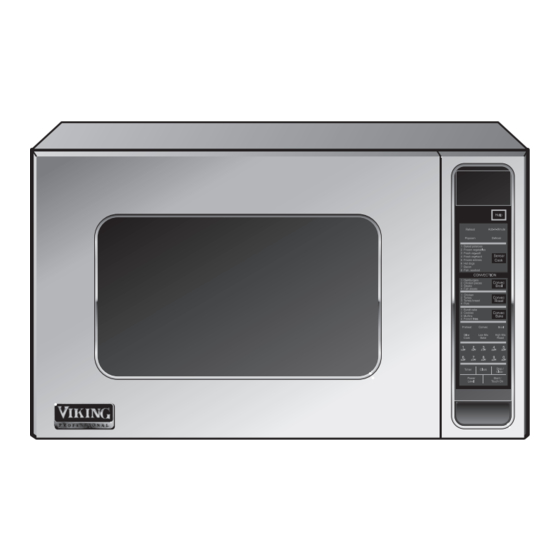
Above model is example only
In the interest of user-safety the oven should be restored to its original condition and only parts identical to those specified should
be used.
WARNING TO SERVICE PERSONNEL: Microwave ovens contain circuitry capable of producing very high voltage and
current. Contact with the following parts may result in a severe, possibly fatal, electrical shock. (Inverter unit that includes
High Voltage Capacitor, High Voltage Power Transformer, High Voltage Rectifier and Heat sink etc., and Magnetron, High
Voltage Harness etc..)
AVOID POSSIBLE EXPOSURE TO EXCESSIVE MICROWAVE ENERGY .......................................................... 2
BEFORE SERVICING ............................................................................................................................................ 2
WARNING TO SERVICE PERSONNEL ................................................................................................................. 4
MICROWAVE MEASUREMENT PROCEDURE (Canada) ..................................................................................... 5
MICROWAVE MEASUREMENT PROCEDURE (USA) .......................................................................................... 6
FOREWORD AND WARNING ............................................................................................................................... 7
PRODUCT SPECIFICATIONS ............................................................................................................................... 8
GENERAL INFORMATION.................................................................................................................................... 8
OPERATION ......................................................................................................................................................... 10
TROUBLESHOOTING GUIDE ............................................................................................................................. 16
TEST PROCEDURE ............................................................................................................................................ 18
COMPONENT REPLACEMENT AND ADJUSTMENT PROCEDURE................................................................. 26
PICTORIAL DIAGRAM ......................................................................................................................................... 33
PARTS LIST ........................................................................................................................................................ 34
PACKING AND ACCESSORIES .......................................................................................................................... 39
Range Corporation
111 Front St., Greenwood, MS 38930
Tel: (888) 845-4641
SERVICE MANUAL
TABLE OF CONTENTS
MICROWAVE OVENS
VMOC205BK
VMOC205WH
VMOC205IB
VMOC205BT
VMOC205SG
VMOC205GG
MODELS
VMOC205BU
VMOC205MS
VMOC205TP
VMOC205SA
VMOC205AR
VMOC205CH
VMOC205AL
VMOC205FG
This document has been published to be used for after
sales service only.
1
Rev 1 (May 2011)
S51M338VMO205
VMOC205LE
VMOC205MJ
VMOC205PM
VMOC205VB
VMOC205CB
VMOC205RR
VMOC205CW
VMOC205OG
VMOC205GM
VMOC205SE
VMOC205PL
VMOC205SS
VMOC205EP
Page
Advertisement
Table of Contents

Summarization of Contents
Safety Precautions and Warnings
Microwave Exposure Prevention
Steps to avoid exposure to excessive microwave energy during servicing.
High Voltage Danger Warnings
Critical warnings about electrical shock hazards from high voltage components.
Service Personnel Safety Guidelines
Essential safety procedures before and after servicing the oven.
Microwave Leakage Measurement
Canadian and US Leakage Standards
Requirements for microwave leakage limits as per standards.
Testing Preparation and Procedures
Steps for preparing equipment and performing leakage tests.
Leakage Measurement Details
Comprehensive procedure for measuring microwave leakage.
Oven Specifications and General Information
General Oven Specifications
Details on power, dimensions, controls, and safety standards.
Electrical Requirements and Diagrams
Information on electrical needs and visual layouts of components.
Oven Operation Modes
Standard Operation Sequences
Description of normal oven operation, off, and cooking states.
Convection and Mixed Cooking
Procedures for convection preheating, operation, and mixed modes.
Advanced Cooking Functions
Details on sensor cooking, automated programs, and fire sensing.
Schematic Diagrams
Oven Operating Condition Schematics
Wiring diagrams illustrating different oven operational states.
Component Functions and Systems
Key Component Descriptions
Functions of door switches, thermistors, and thermal cut-outs.
Convection System and Damper Operation
Explanation of the convection system and the damper mechanism.
Troubleshooting and Component Testing
Component Cause and Effect Analysis
Table correlating problems with defective parts and conditions.
Detailed Component Testing Procedures
Step-by-step tests for high voltage, switching, and sensor components.
Control System and Special Function Testing
Tests for key units, relays, Compu Defrost, and wiring.
Advanced Sensor and PWB Troubleshooting
Tests for humidity sensor, PWB foil patterns, and control unit.
Absolute Humidity Sensor Circuit Analysis
Sensor Structure and Operational Principle
Explanation of the humidity sensor's design and how it works.
Sensor Detector Circuit Diagram
Diagram illustrating the circuit that detects the sensor's output.
Component Replacement and Adjustment
Safety, Wiring, and General Removal
Safety guidelines and basic procedures for component removal.
High Voltage and Core Component Replacement
Procedures for replacing power transformer, magnetron, and HV components.
Motor, Heater, and Damper Component Replacement
Steps for replacing motors, heating elements, and damper assembly.
Control Panel, Door, and Switch Assembly Procedures
Procedures for replacing control panel, door, and related switches.
Door Switches, Adjustment, and Disassembly
Procedures for removing, adjusting, and disassembling door components.
Pictorial Diagram
Oven Component Wiring Diagram
Visual wiring schematic of the microwave oven.
Parts Listing
Electrical, Cabinet, and Control Panel Parts
Lists of electrical, cabinet, and control panel components.
Oven, Door, and Miscellaneous Parts
Lists of general oven parts, door components, and hardware.
Packing and Accessories
Oven Packaging and Included Items
Details on how the microwave oven is packed and its accessories.


Need help?
Do you have a question about the Professional VMOC205SS and is the answer not in the manual?
Questions and answers