Table of Contents
Advertisement
Quick Links
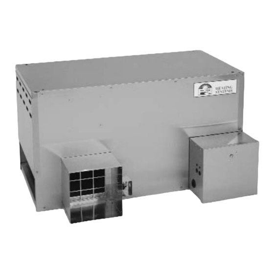
Owner's Manual and Instructions
Agricultural Animal Confinement Building Heaters
Congratulations!
You have purchased the finest agricultural building heater available.
Your new PSI heater incorporates the benefits from the most experienced
manufacturer of heating products using state-of-the-art technology.
We, at PSI, thank you for your confidence in our products and welcome
any suggestions or comments you may have...call us at 608-781-8500.
ATTENTION ALL USERS
This heater has been designed and developed specifically for use as a direct-fired
circulating heater for agricultural animal confinement buildings. The heater is
approved for indoor use only. If you are considering using this product for any
application other than its intended use, then please contact your fuel gas supplier,
or PSI Heating Systems.
W6636 East Avenue North, Onalaska, WI USA
IGNITION
SERIES
TYPE
1450
Pilot
(608) 781-8500
OUTPUT
(KW)
FUEL
Models are
17.6 KW
available in
either L.P. Gas
Vapor Withdrawal
65.9 KW
or Natural Gas
Configurations.
Fax: (608) 783-6115
F150-81619
Advertisement
Table of Contents

Related Manuals for PSI 60


Summary of Contents for PSI 60
- Page 1 Your new PSI heater incorporates the benefits from the most experienced manufacturer of heating products using state-of-the-art technology. We, at PSI, thank you for your confidence in our products and welcome any suggestions or comments you may have...call us at 608-781-8500.
- Page 2 Only properly-trained service people should repair or install this heater. Save this Owner’s Manual for future use and reference. Owner’s Manuals and replacement labels are available at no charge. For assistance, contact PSI at 608-781-8500. WARNING Proper gas supply pressure must be provided to the inlet of the heater.
-
Page 3: Table Of Contents
Contact your local PSI distributor or PSI Heating Systems for configuration number and serial number available. This assistance, or if you have any questions about the use of the information is contained on the dataplate. The dataplate is equipment or its application. -
Page 4: Heater Specifications
Heater Specifications M M o o d d e e l l SPECIFICATIONS L.P. Natural L.P. Natural Fuel Maximum Input 17.6 KW 65.9 KW Ventilation Air Required 428 Cubic Meters 1543 Cubic Meters to Support Combustion per Hour per Hour 10 mbar 10 mbar Burner Manifold Pressure... -
Page 5: Fuel Information For Country Of Destination
FUEL INFORMATION FOR COUNTRY OF DESTINATION Appliance Supply Gas Rate Type Category Pressure L.P. Gas 37 mbar 1.26 kg/hr. 4.73 kg/hr. Great Britain 1.74 m 3 /hr. 6.43 m 3 /hr. Nat. Gas 20 mbar L.P. Gas 50 mbar 1.26 kg/hr. 4.73 kg/hr. -
Page 6: Safety Precautions
Refer to the specification section of the heater’s Owner’s Symptoms of improper combustion affecting livestock Manual, heater dataplate, or contact PSI Heating can be disease, lower feed conversion, or death. FUEL GAS ODOR LP g g as a a nd n n atural g g as h h ave m m an-m m ade o o dorants a a dded s s pecifically f f or d d etection o o f f f uel g g as l l eaks. - Page 7 2. All installations and applications of PSI heaters must 13. This heater is wired for a three-wire electrical system. meet all relevant local, state and national codes.
-
Page 8: Installation Instructions
If a leak is detected, check the components involved for cleanliness in the thread areas and proper application of pipe 1. Read all safety precautions and follow PSI compound before further tightening. Further tighten recommendations when installing this heater. -
Page 9: Air Diverter Installation Instructions
Critical products and/or animals liquid withdrawal system or application. If you are in should be protected by a separate back-up control doubt, contact PSI Heating Systems. system that limits high and low temperatures and also activates appropriate alarms. 13. This heater can be configured for use with either L.P. -
Page 10: Hanging Instructions
HANGING INSTRUCTIONS 1. Assemble according to the illustration and tighten all livestock so that livestock cannot knock the heater, eyebolts securely. tear it loose from its mounting, or damage the heater or its gas supply line in any way. Make sure you FIG. -
Page 11: Thermostat Installation
THERMOSTAT INSTALLATION 2. To C C onnect t t he D D irect W W ired T T hermostat K K it t t o t t he WARNING Control B B ox o o n t t he H H eater: Electrical S S hock H H azard a. -
Page 12: Start-Up Instructions
Start-Up Instructions Follow steps 1 - 5 on initial start-up after heater installation Do not exceed the input rating stamped on the by a qualified gas heater service person. For normal start- dataplate of the heater. Do not exceed the burner up, simply turn thermostat above room temperature. -
Page 13: Cleaning Instructions
Cleaning Instructions WARNING Fire, B B urn, a a nd E E xplosion H H azard This heater contains electrical and mechanical components in the gas management, safety and airflow systems. Such components may become inoperative or fail due to dust, dirt, wear, aging, or the corrosive atmosphere of an animal confinement building. -
Page 14: Service Instructions
Service Instructions MOTOR AND FAN WHEEL ASSEMBLY 1. Shut off the gas supply to the heater. NOTES: a. Fan wheel to motor mount plate spacing must be adjusted to the clearances 2. Disconnect the heater from its electrical supply. specified in the table below before tightening the fan wheel to the motor shaft. -
Page 15: Pilot Light Assembly
PILOT LIGHT ASSEMBLY IMPORTANT 1. Shut off the gas supply to heater. 2. Disconnect the heater from its electrical supply. The hole in the pilot orifice is drilled to a specific diameter to match the fuel and gas pressure being used. Do not poke or 3. -
Page 16: Thermocouple
THERMOCOUPLE 1. Shut off the gas supply to heater. Remove the lead connector nut threaded into the power unit on the gas control valve. 2. Disconnect the heater from its electrical supply. 8. To assemble, reverse above procedure. 3. Let the heater cool down so the pilot assembly is cool IMPORTANT to touch. -
Page 17: Gas Control Valve
GAS CONTROL VALVE g. When heater lights, the gas gauge will read 25 WARNING MBAR for LP vapor or 10 MBAR for natural gas pressure. This pressure is the flowing gas pressure Fire a a nd E E xplosion H H azard necessary for the heater to deliver its maximum Do not disassemble the gas control valve. -
Page 18: Testing The Manual Reset High Limit Switch
TESTING THE MANUAL RESET HIGH LIMIT SWITCH 5. Allow the switch cool down for about a minute before WARNING firmly pressing the reset button on the switch. Fire H H azard Do not operate the appliance with the high limit switch 6. -
Page 19: Troubleshooting Guide
Pilot will not light ..... . . 20 • Thermocouple D D iagnostic K K it - (PSI Part No. 550-08506) -
Page 28: Electrical Connection And Ladder Diagram
Electrical Connection and Ladder Diagram CAUTION Always refer to the heater’s electrical connection diagram when servicing to avoid wiring errors and heater malfunction. Check for proper operation after servicing. WARNING: THIS HEATER MAY START AT ANY TIME FUSE GAS CONTROL VALVE GREEN/ BROWN... -
Page 29: Heater Component Function
Heater Component Function Air Proving Switch Pilot Light Orifice Safety device used to insure that the proper air flow is being A metering device used to supply gas for the dual purpose of achieved before the gas valve is opened. igniting the main burner and heating the thermocouple. -
Page 30: Parts Identification
Parts Identification PARTS SCHEMATIC... -
Page 31: Parts List
PARTS LIST Item Description Heat Chamber Assembly Stainless Steel 81040 81043 Galvanized Steel 81041 81042 Bracket, Burner Mount 80251 80404 Control Box Assembly Stainless Steel 81427 Galvanized Steel 81426 Terminal Strip 08253 Gasket 80456 Cord, Power 20359 Transformer 23145 Motor and Blower Assembly Stainless Steel 80797 80504... -
Page 32: Label Identification
NOTE 1: High Limit, Part No. 05566 is 350º F. (177º C.), High Limit Part Number 84144 is 300º F. (149º C.), High Limit Part No. 03933 is 275º F. (135º C.), High Limit, Part No. 81108 is 325º F. (163º C.). Label Identification 85870 20384 DANGER PSI LABEL HIGH VOLTAGE (OUTSIDE) 80763 CE LABEL TECH DATA 60 LP 80818... -
Page 33: Fastener Selection Table
FASTENER SELECTION TABLE Description Application Part Number Bolt, Eye Hanging of Heater 130-07715 Chain Hanging of Heater 130-07716 Stud Pilot Mounting 130-07827 Screw, #8 x 3/8 All Other Applications F130-83065... -
Page 34: Warranty Policy
EQUIPMENT PSI Heating Systems warrants that the component parts of A warranty card on file at PSI will automatically qualify a unit its equipment are free from defects in material and and its component parts for warranty consideration. If a... - Page 35 EC Declaration of Conformity PSI Heating Systems Manufacturer: W6636 East Avenue Tel. 608-781-8500 Onalaska, Wisconsin 54650 Fax 608-783-6115 U.S.A. Declaration of Conformity: We declare that the equipment designated below meets the requirements of the EC Gas Appliance Directive, Annex I and Annex II, and Low Voltage Directive, Annex 1 on the basis of type evaluation of design and manufacture.
Need help?
Do you have a question about the 60 and is the answer not in the manual?
Questions and answers