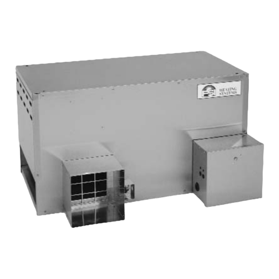
PSI 1450 Series Owner's Manual And Instructions
Agricultural animal confinement building heaters
Hide thumbs
Also See for 1450 Series:
- Owner's manual and instructions (35 pages) ,
- Owner's manual and instructions (34 pages) ,
- Owner's manual and instructions (28 pages)
Table of Contents
Advertisement
Quick Links
Owner's Manual and Instructions
Agricultural Animal Confinement Building Heaters
IGNITION
OUTPUT
SERIES
TYPE
(kW)
FUEL
Models are
17.6
available in
either Propane
Direct Spark
1450
Vapor Withdrawal
65.9
or Natural Gas
Configurations.
Congratulations!
You have purchased the finest agricultural building heater available.
Your new PSI heater incorporates the benefits from the most experienced
manufacturer of heating products using state-of-the-art technology.
We, at PSI, thank you for your confidence in our products and welcome
any suggestions or comments you may have...call us at: USA 01-608-781-8500.
ATTENTION ALL USERS
This heater has been designed and developed specifically for use as a direct-fired
circulating heater for agricultural animal confinement buildings. The heater has
been evaluated by BG Technology and found to conform to essential health and
safety requirements as required by the Gas Appliance Directive, Low Voltage
Directive, and Electromagnetic directive. The heater is approved for indoor use or
outdoor use with the approved air handling kit. If you are considering using this
product for any application other than its intended use, then please contact your
fuel gas supplier, or PSI Heating Systems.
W6636 East Avenue North, Onalaska, WI USA
■
(608) 781-8500
■
Fax: (608) 783-6115
F150-81033-B
Advertisement
Table of Contents

Related Manuals for PSI 1450 Series


Summary of Contents for PSI 1450 Series
- Page 1 Your new PSI heater incorporates the benefits from the most experienced manufacturer of heating products using state-of-the-art technology. We, at PSI, thank you for your confidence in our products and welcome any suggestions or comments you may have...call us at: USA 01-608-781-8500.
- Page 2 Save this Owner’s Manual for future use and reference. ■ Owner’s Manuals and replacement labels are available at no charge. For assistance, contact PSI at +1-608-781-8500. WARNING ■ Proper gas supply pressure must be provided to the inlet of the heater.
-
Page 3: Table Of Contents
Contact your local PSI distributor or PSI Heating Systems for This manual will instruct you in the operation and care of assistance, or if you have any questions about the use of the your unit. -
Page 4: Heater Specifications
Heater Specifications Models S S P P E E C C I I F F I I C C A A T T I I O O N N S S Maximum Input (kW) 17.6 65.9 Ventilation Air Required 1543 to Support Combustion (m /hr) I 3P... -
Page 5: Fuel Information For Country Of Destination
FUEL INFORMATION FOR COUNTRY OF DESTINATION Propane Rate (kg/hour) Gas Category & Pressure Destination Countries (mbar) HU & NL (30) (36) BE, CH, CZ, ES, 1.26 4.73 (37) GB, IE, PT, SI & SK BE, CH, DE, ES & NL (50) (Butane) (Butane) -
Page 6: Safety Precautions
Refer to the specification section of the heater’s Owner’s ■ Symptoms of improper combustion affecting livestock Manual, heater dataplate, or contact PSI Heating can be disease, lower feed conversion, or death. FUEL GAS ODOR LP g g as a a nd n n atural g g as h h ave m m an-m m ade o o dorants a a dded s s pecifically f f or d d etection o o f f f uel g g as l l eaks. - Page 7 There is a hot lead, neutral lead, and a ground lead. The heater may or may not incorporate a plug in the 2. All installations and applications of PSI heaters must power cord on the heater and the plug may or may not meet all relevant local, state and national codes.
-
Page 8: Installation Instructions
Further tighten the gas connections as necessary to stop the leak. 1. Read all safety precautions and follow PSI After all connections are checked and any leaks are recommendations when installing this heater. -
Page 9: Air Diverter Installation Instructions
Contact your gas supplier, or activates appropriate alarms. PSI Heating Systems if you have any questions. 16. Take time to understand how to operate and maintain 14. This heater can be configured for use with either L.P. -
Page 10: Hanging Instructions
HANGING INSTRUCTIONS FIG. 3 1. Assemble according to the illustration and tighten all eyebolts securely. FIG. 2 EYEBOLT CHAIN OPTIONAL INDOOR REGULATOR FLAT WASHER MOUNTING LOCATION BLACK PIPE THROUGH WALL GAS HOSE CAGE NUT CASE TOP THERMOSTAT VENT LINE 2. Be sure heater is securely fastened and is hanging CORD level. -
Page 11: Thermostat Installation
THERMOSTAT INSTALLATION b. The thermostat cordset must use a minimum of WARNING 18 gauge wire consisting of a hot lead, neutral Electrical S S hock H H azard lead, and a ground lead. ■ Disconnect the electrical supply before connecting the c. -
Page 12: Start-Up Instructions
Start-Up Instructions Follow steps 1 - 6 on initial start-up after heater installation The ignition control will make three trials for ignition. by a qualified service person. For normal start-up, simply set If ignition is not proven after the third trial, the control the thermostat to a setting above room temperature. -
Page 13: Cleaning Instructions
Make sure all markings are legible and not cut, torn, or otherwise damaged. Any damaged markings should be replaced immediately. Markings are available at no cost by contacting PSI. -
Page 14: Service Instructions
Service Instructions MOTOR AND FAN WHEEL ASSEMBLY 1. Shut off the gas supply to the heater. NOTES: a. Fan wheel to motor mount plate spacing must be adjusted to the clearances 2. Disconnect the heater from its electrical supply. specified in the table below before tightening the fan wheel to the motor shaft. -
Page 15: Igniter And Flame Sensor
IGNITER AND FLAME SENSOR ■ 1. Close the fuel supply valves to the heater and The igniter/sensor assembly may require cleaning due disconnect the heater from its electrical supply. to accumulations of dust and dirt over a period of time, thereby affecting its ability to ignite fuel gas and sense 2. -
Page 16: Gas Pressure Checks
GAS PRESSURE CHECKS C. Reading P P ressures WARNING 1. With the heater operating, the pressure gauges Fire a a nd E E xplosion H H azard should read the pressures specified on the dataplate. ■ Do not disassemble the gas control valve. 2. -
Page 17: Testing The Manual Reset High Limit Switch
TESTING THE MANUAL RESET HIGH LIMIT SWITCH 5. Allow the switch cool down for about a minute before WARNING firmly pressing the reset button on the switch. Fire H H azard ■ Do not operate the appliance with the high limit switch 6. -
Page 18: Troubleshooting Guide
Troubleshooting Guide READ THIS ENTIRE SECTION BEFORE Components should be replaced only after each step within BEGINNING TO TROUBLESHOOT PROBLEMS. the flow chart has been completed and replacement is suggested in the flow chart. Refer to the Servicing sections as necessary to obtain information on disassembly and WARNING replacement procedures of the component. -
Page 23: Electrical Connection And Ladder Diagram
Electrical Connection and Ladder Diagram 17.6 kW MODEL CAUTION - REFER TO THE HEATER'S ELECTRICAL CONNECTION DIAGRAM WHEN SERVICING THE HEATER'S ELECTRICAL COMPONENTS TO AVOID WIRING ERRORS & EQUIPMENT MALFUNCTION. CHECK FOR PROPER OPERATION AFTER SERVICING. WARNING: THIS HEATER MAY START AT ANY TIME HIGH VOLTAGE IGNITION LEAD IGNITER GREEN/YELLOW... -
Page 24: Kw Model
Electrical Connection and Ladder Diagram 65,9 kW MODEL CAUTION: REFER TO HEATERS ELECTRICAL CONNECTION DIAGRAM WHEN SERVICING THE HEATERS ELECTRICAL COMPONENTS TO AVOID WIRING ERRORS AND EQUIPMENT MALFUNCTION. CHECK FOR PROPER OPERATION AFTER SERVICING. WARNING: THIS HEATER MAY START AT ANY TIME HIGH VOLTAGE IGNITION LEAD IGNITER BURNER... -
Page 25: Heater Component Function
Heater Component Function Air Proving Switch High Limit Switch Safety device used to insure that the proper air flow is being Safety device wired into the control system which is used to achieved before the gas valve is opened. break an electrical circuit to the gas control valve in event of overheat situation. -
Page 26: Parts Identification
Parts Identification PARTS SCHEMATIC... -
Page 27: Parts List
PARTS LIST Item Description High limit switch at heat chamber 84144 81108 High limit switch at blower end 84144 81108 Fan Wheel 80972 80973 Air Proving Switch ------------------80324------------------ Motor 80971 81803 Motor Mount with Hardware 82118 82117 Fan Housing Assembly Stainless Steel 81804 Galvanized Steel... -
Page 28: Label Identification
Label Identification 85870 PSI LABEL 20384 DANGER 80763 CE LABEL HIGH VOLTAGE 21012 WARNING 21008 WARNING 20385 ISOLATE TECH DATA 20453 HOT SURFACE 20453 HOT SURFACE 25222 RESET SWITCH 21270 ELECTRICAL GROUNDING WIRING DIAGRAM 81890 - 65.9 KW 21304 INSTRUCTIONS 20158 INSTRUCTIONS 81922 - 17.6 KW... -
Page 29: Warranty Policy
EQUIPMENT PSI Heating Systems warrants that the component parts of A warranty card on file at PSI will automatically qualify a unit its equipment are free from defects in material and and its component parts for warranty consideration. If a...
Need help?
Do you have a question about the 1450 Series and is the answer not in the manual?
Questions and answers