
Related Manuals for rizoma BS305


Summarization of Contents
General Conditions
Safety Precautions
Essential safety instructions, warnings about danger, personal injury, and death if not followed.
Product Inspection and Maintenance
Guidelines for regular inspection, maintenance, and handling of damaged parts.
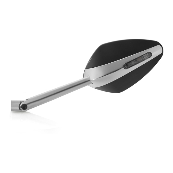
Mirror 'Veloce L' Product Details
Functionality and Indicator Replacement
Describes the mirror's function as a replacement for original mirrors with integrated indicators.
Mounting Preparation and Schematics
Kit Completeness and Safety Checks
Verify all kit components and perform safety checks before installation.
Electrical Wiring Schematics Overview
Introduction to wiring diagrams for LED and bulb indicators.
Installation Guide
Step 1: Mechanical Installation
Instructions for correct mechanical installation, including warranty and safety aspects.
Electrical Connections and Wiring
Step 2.0: General Wiring Guidelines
Check OEM power, use correct connectors, avoid cutting wires.
Step 2.1: Wiring and Resistor Installation
Connecting Rizoma wiring, managing flash rate with resistors or relays.
Mirror Mounting
Step 3: Mirror Adapter Installation
Install the correct adapter before assembling the mirror.
Mirror Adjustment
Step 4.0: Mirror Rotation Adjustment
Rotate mirror to find desired position, then tighten with torque wrench.
Step 4.1: Mirror Height Adjustment
Adjust mirror height for correct position, then tighten with torque wrench.
Step 4.2: Mirror Body Rotation
Rotate mirror body for optimal viewing angle after mounting.
Wiring Diagrams
Schema 1: LED Indicators
Assembly diagram for motorcycles with LED indicators.
Schema 2: Bulb Indicators (6W to <10W)
Assembly diagram for motorcycles with 6W to <10W bulb indicators.
Schema 3: Bulb Indicators (10W)
Assembly diagram for motorcycles with 10W bulb indicators.
Schema 4: Bulb Indicators (21W)
Assembly diagram for motorcycles with 21W bulb indicators.
Wiring Compatibility Tables
BMW Model Wiring Schematics
Table cross-referencing BMW models with appropriate wiring schemas.
Ducati Model Wiring Schematics
Table cross-referencing Ducati models with appropriate wiring schemas.
Ducati Model Wiring Schematics (Cont.)
Table cross-referencing Ducati models with appropriate wiring schemas.
Honda, Husqvarna, Kawasaki Model Wiring Schematics
Table cross-referencing Honda, Husqvarna, Kawasaki models with wiring schemas.
Kawasaki, KTM Model Wiring Schematics
Table cross-referencing Kawasaki, KTM models with wiring schemas.
Moto Guzzi, MV Agusta, Suzuki, Triumph Model Wiring Schematics
Table cross-referencing Moto Guzzi, MV Agusta, Suzuki, Triumph models with wiring schemas.
Triumph, Yamaha Model Wiring Schematics
Table cross-referencing Triumph, Yamaha models with wiring schemas.
Yamaha, Harley Davidson Model Wiring Schematics
Table cross-referencing Yamaha, Harley Davidson models with wiring schemas.
Harley Davidson Model Wiring Schematics (Cont.)
Table cross-referencing Harley Davidson models with wiring schemas.
Exceptions and Kit Purchases
Model-Specific Resistor Exceptions
Models requiring specific kits instead of included resistors for proper indicator function.
Rider Safety and Product Information
Riding Safety Recommendations
Advice on safety clinics, helmets, gear, and tire pressure for safe riding.
Rider Responsibility and Italian Law
User acknowledges riding limits and agrees Italian law applies to claims.
Stunt Riding Dangers and Risks
Warnings about the extreme dangers and risks associated with stunt riding.
Rizoma Product and Information Changes
Rizoma reserves the right to make changes to products and information without notice.
Legal and Homologation Notes
Road Homologation Disclaimer
Statement that not all products are approved for road circulation where homologation is required.
Need help?
Do you have a question about the BS305 and is the answer not in the manual?
Questions and answers