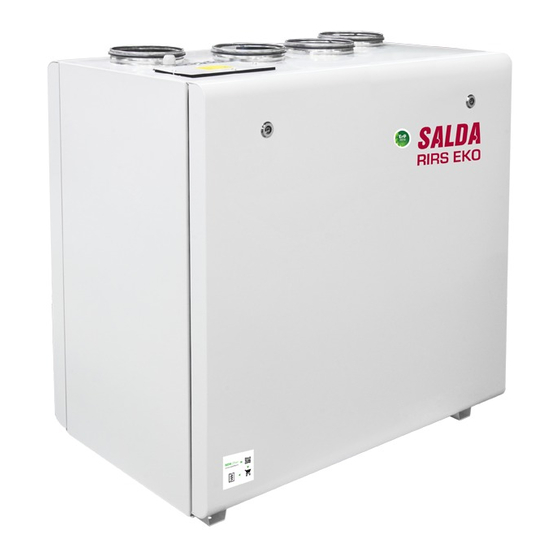
Salda RIRS 700 VEL EKO 3.0 Mounting And Installation Instructions Manual
Source: salda.lt/en, vetter-lufttechnik.de
Table of Contents
Advertisement
Advertisement
Table of Contents

Summarization of Contents
SYMBOLS AND SAFETY INFORMATION
Technical Label Identification
Describes the unit's technical label and its components for identification.
Duct Connection Indicators
Explains the symbols used for different air duct connections on the unit.
General Safety Warnings and Precautions
Provides crucial warnings, safety rules, and specific danger points for safe operation.
UNIT SPECIFICATIONS
Dimensions, Weight, and Electrical Data
Presents tables with physical dimensions, weight, and technical electrical data for unit models.
CONSTRUCTION OVERVIEW
Internal Component Identification Diagram
Illustrates the unit's internal components with numerical labels for reference.
OPERATING CONDITIONS, PACKAGING, AND TRANSPORT
Environmental Operating Parameters
Illustrates temperature and humidity limits for safe and optimal unit operation.
Package Specifications and Lifting Procedures
Details package dimensions, quantity, and forklift lifting procedures.
INSTALLATION PREPARATION AND MOUNTING
Unit Unpacking and Component Check
Guides on unpacking, checking components, and required installation space.
Mounting Guidelines and Requirements
Provides instructions and recommendations for securely mounting the unit.
AIR DUCT AND CONNECTION DIAGRAMS
Air Duct Connection and Component Labels
Shows air duct connections and explains symbols in connection diagrams.
PCB Input/Output Definitions
Lists the function of Printed Circuit Board inputs and outputs for system integration.
ELECTRICAL HOOKUP AND INITIAL START-UP
Electrical Connection Safety Guidelines
Instructs on safe and proper electrical connection to the unit.
Pre-Start-Up Checks and Troubleshooting
Lists essential checks before operation and common issues with solutions.
Filter Maintenance Procedures
Details how to maintain and replace air filters for optimal performance.
COMPONENT MAINTENANCE PROCEDURES
Fan, Heat Exchanger, and Heater Care
Outlines maintenance procedures for the fan, heat exchanger, and electrical heater.
AUTOMATIC CONTROL SYSTEM FEATURES
Temperature Regulation and Special Modes
Explains temperature control, BOOST, and START/STOP features for optimized operation.
Ventilation, Cooling, and Fan Status
Covers ventilation modes, cooling strategies, and fan status indicators.
SYSTEM PROTECTION AND BMS INTEGRATION
Heater Protection Mechanisms
Details safety mechanisms for water and electric heaters against damage.
ModBus Communication Setup for BMS
Explains BMS connection, ModBus protocol, and port configuration for integration.
MODBUS COMMUNICATION PROTOCOL
Modbus Address Map and Data Definitions
Lists Modbus addresses, functions, and data definitions for unit control.
ELECTRICAL WIRING AND SYSTEM ADJUSTMENT GUIDELINES
HVAC Unit Electrical Connection Safety
Provides guidelines for safe and compliant electrical hookups to the HVAC unit.
Control Panel Connection and Adjustment
Details control panel connection, adjustment, and relevant wiring diagrams.
CONTROL BOARD RG1 INFORMATION
LED Indicator Meanings and Status
Explains the status indicated by each LED on the RG1 control board.
CONTROLLER AND COMPONENT LABELING
Terminal Labels and Descriptions
Lists terminal contacts and their descriptions on the main controller unit.
DETAILED COMPONENT TERMINAL ASSIGNMENTS
Component Terminal Connections Table
Provides a comprehensive table of terminal assignments for various unit components.
REGULAR SYSTEM CHECKS AND INSPECTIONS
Switching Device Visual Inspection
Describes periodic visual checks for the switching device (contactor) for proper function.
ELECTRICAL CONNECTION DIAGRAMS
RIRS 400 VE EKO 3.0 Wiring Diagram
Shows the complete electrical wiring for the RIRS 400 VE EKO 3.0 model.
ELECTRICAL CONNECTION DIAGRAMS
RIRS 400 VW EKO 3.0 Wiring Diagram
Shows the complete electrical wiring for the RIRS 400 VW EKO 3.0 model.
ELECTRICAL CONNECTION DIAGRAMS
RIRS 700 VE EKO 3.0 Wiring Diagram
Shows the complete electrical wiring for the RIRS 700 VE EKO 3.0 model.
ELECTRICAL CONNECTION DIAGRAMS
RIRS 700 VW EKO 3.0 Wiring Diagram
Shows the complete electrical wiring for the RIRS 700 VW EKO 3.0 model.
ECODESIGN DATA
400 Series EcoDesign Performance Data
Presents Ecodesign performance data for the 400 series RIRS EKO 3.0 models.
ECODESIGN DATA
700 Series EcoDesign Performance Data
Presents Ecodesign performance data for the 700 series RIRS EKO 3.0 models.
DECLARATION OF CONFORMITY
Manufacturer Compliance Statement and Standards
Confirms compliance with EU directives and applied harmonized standards.
WARRANTY AND SUPPORT
Warranty Terms, Exclusions, and Coupon
Details warranty conditions, exclusions, and information about the limited warranty coupon.
PRODUCT MAINTENANCE RECORD
Maintenance Schedule and Log Table
Provides a table for recording routine maintenance activities and their dates.


Need help?
Do you have a question about the RIRS 700 VEL EKO 3.0 and is the answer not in the manual?
Questions and answers