Advertisement
Table of Contents
- 1 Specifications
- 2 Installation
- 3 Mounting Wiring Subbase
- 4 Wiring Subbase
- 5 Final Wiring Check
- 6 Static Checkout
- 7 Equipment Recommended
- 8 General Instructions
- 9 Principal Technical Features
- 10 Sequence of Operation
- 11 Settings and Adjustments
- 12 Selectable Site-Configurable Jumpers
- 13 Safety and Security
- 14 License Agreement
- Download this manual
EC7830A, RM7830A,
EC7850A, RM7850A
7800 SERIES Relay Modules
APPLICATION
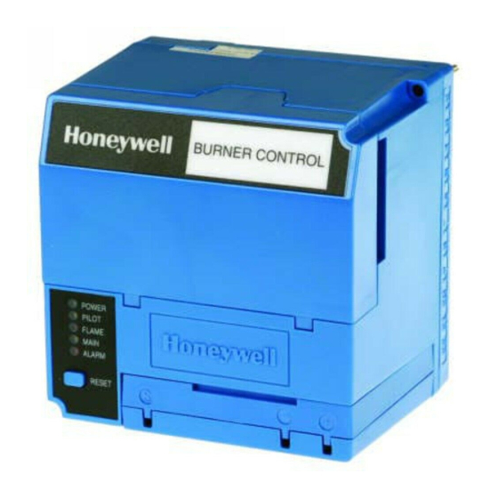
The Honeywell EC/RM7830A and EC/RM7850A are
microprocessor-based integrated burner controls for
automatically fired gas, oil, or combination fuel single
burner full modulation (EC/RM7850A) or on/off
(EC/RM7830A) applications. The EC/RM7830A;
EC/RM7850A system consists of a relay module, subbase,
amplifier, and purge card. Options include keyboard
display module (KDM), Data ControlBus™ Module and
remote display mounting.
Functions provided by the EC/RM7830A and
EC/RM7850A include automatic burner sequencing,
flame supervision, system status indication, system or
self-diagnostics and troubleshooting. Text readout on the
Keyboard Display Module is available in various
languages.
This document covers the following 7800 Series Relay
Modules:
EC7830A1033
EC7830A1066
EC7850A1072
EC7850A1080
EC7850A1122
RM7830A1003
RM7830A1029
RM7850A1001
RM7850A1019
EC7830A2033
EC7830A2066
EC7850A2072
EC7850A2080
EC7850A2122
RM7830A2003
RM7830A2029
RM7850A2001
RM7850A2019
SIL
3
Capable
0063
INSTALLATION INSTRUCTIONS
This document provides installation and static checkout
instructions. Other applicable publications are:
Form
Number
32-00110
S7800A2142 4-line LCD Keyboard Display
Module Product Data
32-00166
204729A/C KDM NEMA4 Covers for 4-line
LCD KDM
32-00235
R7824, R7847, R7848, R7849, R7861,
R7886 Flame Amplifiers for the 7800
SERIES Product Data
65-0084
Q7800A,B 22-Terminal Wiring Subbase
Product Data
65-0090
S7800A Keyboard Display Module Product
Data
65-0091
S7810A Data ControlBus™ Module
Product Data
65-0095
S7820 Remote Reset Module Product
Data
65-0097
221729C Dust Cover Packing Instructions
65-0131
221818A Extension Cable Assembly
Product Data
65-0228
S7810B Multi-Drop Switch Module
Product Data
65-0229
7800 SERIES Relay Modules Checkout
and Troubleshooting Product Data
65-0249
S7810M ModBus Module (For CE ,
Modbus module S7810M1029 only).
65-0295
50023821-001/2 KDM NEMA4 Covers for
classic 2-line VFD KDM
Description
32-00198-01
Advertisement
Table of Contents

Related Manuals for Honeywell RM7850A1019


Summarization of Contents
SPECIFICATIONS
Electrical Ratings
Details voltage, frequency, power, and fusing ratings.
Environmental Ratings
Specifies operating and storage temperatures, humidity, and vibration limits.
SIL 3 Capable
States the safety integrity level capability for systems.
Approvals
Lists certifications and approvals from various bodies.
European Directives
Lists relevant European Union directives impacting the product.
Applicable Standards
Lists industry standards the product complies with.
INSTALLATION
General Installation Precautions
Outlines crucial steps and warnings before and during installation.
Mounting Wiring Subbase
Subbase Mounting Guidelines
Provides instructions for correctly mounting the wiring subbase.
Relay Module and Subbase Compatibility
Series 1000 Relay Modules Compatibility
Details compatibility of 1000 series modules with subbases.
Series 2000 Relay Modules Compatibility
Details compatibility of 2000 series modules with subbases.
Subbase Compatibility Notes
Explains compatibility based on software revision and subbase models.
Wiring Subbase
Wiring Subbase Guidelines
Provides essential instructions for wiring the subbase.
KDM Power Supply and Module Limits
Advises on KDM power supply requirements and module combination limits.
Final Wiring Check
Wiring Check Steps
Lists steps for performing a final wiring check before installation.
Mounting EC/RM7830A; EC/RM7850A Relay Module
Relay Module Mounting Guidelines
Provides instructions for mounting the relay module vertically or horizontally.
STATIC CHECKOUT
Static Checkout Procedure
Explains how to perform checkout tests before installing the relay module.
Recommended Equipment for Checkout
Lists the tools and materials needed for static checkout.
General Instructions for Checkout
Provides overarching guidance and steps for performing static checkout.
General Instructions
Static Checkout General Instructions
Provides general guidance for performing static checkout tests.
Recommended Equipment for Static Checkout
Lists necessary tools and materials for static checkout.
Safety Precautions during Checkout
Highlights critical safety warnings and cautions for testing.
Mounting Other System Components
Component Mounting References
Refers to applicable specifications for mounting other system components.
PRINCIPAL TECHNICAL FEATURES
Relay Module Technical Features
Describes the core technical capabilities of the relay module.
Safety Shutdown (Lockout) Occurs If:
Safety Shutdown Conditions (Lockout)
Details the specific conditions that trigger a safety shutdown or lockout.
Normal Start-Up Purge
Normal Start-Up Purge Procedure
Explains the steps and timing for the initial purge sequence.
Ignition Trials
Ignition Trial Phases
Details the preignition, first safety time, and pilot stabilization phases.
Run
Run Phase Operation
Describes the burner's operation in the run phase.
Postpurge
Postpurge Sequence
Explains the post-run purge cycle.
Run/Test Switch
Run/Test Switch Functionality
Explains how the Run/Test switch alters the burner sequence.
Run/Test Switch Operation Note
Important note on using the TEST mode of the Run/Test switch.
SETTINGS AND ADJUSTMENTS
Selectable Site-Configurable Jumpers
Explains the function and configuration of site-configurable jumpers.
Jumper Clipping Warning
Jumper Clipping Warning Details
Warns about consequences of clipping jumpers after 200 hours of operation.
Flame Signal Measurement
Flame Signal Measurement Procedure
Instructs on measuring flame signal as per amplifier specs.
SAFETY AND SECURITY
Physical Device Protection
Recommends measures for physical security and access control to the device.
Modbus & DDL Interface Security
Addresses security considerations for Modbus and DDL interfaces.
License Agreement
States restrictions on copying and reverse engineering.
For More Information
Honeywell Product Information
Provides contact information and website for Honeywell products.
Need help?
Do you have a question about the RM7850A1019 and is the answer not in the manual?
Questions and answers