Table of Contents
Advertisement
Quick Links
M a n u a l
F o r
O p e r a t i o n
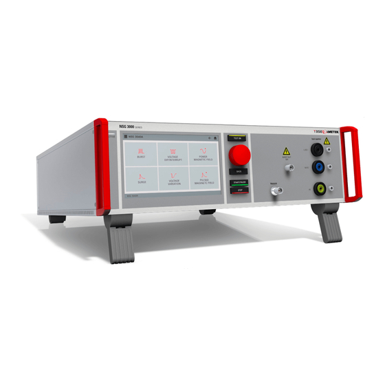
NSG 3000A series
The ultra-compact simulator
and its system modules
NSG 3040A series
NSG 3060A series
Sys App 6.0.0 or higher
The NSG 3000A series, is a versatile tester series to cover
transient and power fail requirements, according to international
standards (basic and generic standards) and product family
standards. With the intuitive touch panel, the NSG 3000A series
is the most economical solution for tests during development as
well as for full-compliant immunity tests and CE Marking for
single phase DUT with the ability to be extended for testing
three-phase DUTs by means of an automatically controlled
external coupling network up to 100 A.
AMETEK CTS supplies a large range of accessories for the
various applications such as magnetic field tests and more.
Version: 1.04 / 03.03.2020
Replaces: 1.03 / 05.09.2019
Filename: UserManual-NSG 3000A series-E-V1.04.doc
Print date: 03.03.2020
EN/IEC 61000-4-4
EN/IEC 61000-4-5
EN/IEC 61000-4-8
EN/IEC 61000-4-9
EN/IEC 61000-4-11
EN/IEC 61000-4-12
EN/IEC 61000-4-29
EN 61000-6-1
EN 61000-6-2
Advertisement
Table of Contents

Related Manuals for Teseq NSG 3040A Series


Summarization of Contents
General Information
Product Purpose and Functionality
Describes the NSG 3000A series system's purpose as a compact simulator for immunity testing.
Warranty Terms and Conditions
Outlines AMETEK CTS's warranty policy and conditions for product use and service.
Recycling and Disposal Guidelines
Provides information on product recycling, disposal, and compliance with RoHS and WEEE directives.
Safety Information
General Safety Guidelines
Restricts equipment use to authorized personnel and warns against pacemaker use near the instrument.
Electrical Connection Safety
Details safe connection to mains and PE, emphasizing protective earth and cable handling.
General Hazards and Precautions
Highlights high voltages, hazardous voltages in removed covers, and caution during servicing.
Operator Responsibilities and Precautions
Defines operator duties for correct operation and warns about potential EMI radiation effects.
Installation and System Configuration
Installation Safety Instructions
Emphasizes national regulations, use in non-explosive atmospheres, and EUT connection timing.
Grounding and Power Connection
Explains the necessity of two independent ground connections for the system and EUT.
System Configuration Procedure
Guides through configuring the NSG 30x0 generator with EUT and accessories.
Software and Firmware Updates
Details procedures for updating the generator's software and firmware via USB.
Technical Specifications
EFT Burst Specifications (IEC 61000-4-4)
Provides detailed technical data for EFT Burst tests, including voltage, pulse duration, and output.
Surge Immunity Specifications (IEC 61000-4-5)
Lists technical data for Surge Immunity, covering test levels, waveforms, and coupling networks.
Magnetic Field Test Specifications (IEC 61000-4-9)
Details specifications for Pulsed Magnetic Field tests, including levels, waveforms, and required hardware.
Voltage Dips & Interruptions Specs (IEC 61000-4-11)
Provides technical data for Power Fail Generator tests, including dips, interruptions, and variations.
Ring Wave Specifications (IEC 61000-4-12)
Lists technical data for Ring Wave Immunity, including voltage, frequency, and test routines.
Maintenance and Calibration
Device Maintenance and Cleaning
Describes general maintenance, cleaning procedures, and precautions for the generator.
Calibration and Verification Guidelines
Provides guidelines for factory calibration, in-house verification, and calibration intervals.
EFT Burst Testing Procedures
EFT Burst Operation Modes
Explains Quick Start, Standard, User, and STEP routines for EFT Burst testing.
Burst Settings and Limits Configuration
Details configuration of signal trigger, trigger out, EUT monitor, and burst impulse limits.
EFT Burst Test Setup
Illustrates test setups, including connections with capacitive coupling clamps.
Surge Immunity Testing Procedures
Surge Testing Operation Modes
Covers Quick Start, Standard, User, and STEP routines for Surge Immunity testing.
Surge Pulse Settings and Configuration
Details configuration of signal trigger, EUT monitor, and HV-COM capacitance settings.
Surge Coupling/Decoupling Networks
Explains coupling to power supply lines and I/O lines, including safety precautions.
Magnetic Field Testing Procedures
Pulsed Magnetic Field Operation
Describes operation modes like Quick Start, Standard, and User routines for magnetic field tests.
Required Device Settings for Magnetic Field Test
Details necessary setup for variable transformers, current transformers, and antennas.
Voltage Dips, Interruptions & Variations Testing
Voltage Dips and Interruption Tests
Explains test setup and operation for voltage dips and interruptions using transformers.
Power Fail Test Modes and Operation
Details operating modes for Power Fail tests, including PF1, PF2, and Delta U modes.
Variable Transformers for Voltage Tests
Describes the TVT 1-250-16 and VAR 3005A-S16 transformers for voltage variation tests.
Telecom Surge Immunity Testing
Telecom Surge Operation Modes
Covers Quick Start, Standard, Extended, and User routines for Telecom Surge testing.
Telecom Surge Pulse Settings
Details configuration parameters for Telecom Surge pulses, including signal trigger and EUT monitor.
Ring Wave Immunity Testing
Ring Wave Operation Modes
Explains Quick Start, Standard, User, and STEP routines for Ring Wave testing.
Ring Wave Pulse Settings
Details configuration parameters for Ring Wave pulses, including signal trigger and EUT monitor.
Ring Wave Coupling/Decoupling
Describes coupling to AC/DC power supply lines and I/O lines for Ring Wave testing.
Appendix and Technical Diagrams
CE Conformity Declarations
Lists CE conformity declarations for NSG 3040A, NSG 3060A, and accessories.
NSG 3040A Series General Block Diagram
Provides a general block diagram illustrating the internal components of the NSG 3040A series.
Need help?
Do you have a question about the NSG 3040A Series and is the answer not in the manual?
Questions and answers