Table of Contents
Advertisement
Quick Links
M a n u a l
F o r
O p e r a t i o n
NSG 3000A series
The ultra-compact simulator
and its system modules
NSG 3040A series
NSG 3060A series
Sys App 6.0.0 or higher
The NSG 3000A series, is a versatile tester series to cover
transient and power fail requirements, according to international
standards (basic and generic standards) and product family
standards. With the intuitive touch panel, the NSG 3000A series
is the most economical solution for tests during development as
well as for full-compliant immunity tests and CE Marking for
single phase DUT with the ability to be extended for testing
three-phase DUTs by means of an automatically controlled
external coupling network up to 100 A.
AMETEK CTS supplies a large range of accessories for the
various applications such as magnetic field tests and more.
Version: 1.04 / 03.03.2020
Replaces: 1.03 / 05.09.2019
Filename: UserManual-NSG 3000A series-E-V1.04.doc
Print date: 03.03.2020
EN/IEC 61000-4-4
EN/IEC 61000-4-5
EN/IEC 61000-4-8
EN/IEC 61000-4-9
EN/IEC 61000-4-11
EN/IEC 61000-4-12
EN/IEC 61000-4-29
EN 61000-6-1
EN 61000-6-2
Advertisement
Table of Contents

Subscribe to Our Youtube Channel
Related Manuals for Teseq NSG 3000A Series


Summary of Contents for Teseq NSG 3000A Series
- Page 1 NSG 3040A series NSG 3060A series Sys App 6.0.0 or higher The NSG 3000A series, is a versatile tester series to cover EN/IEC 61000-4-4 transient and power fail requirements, according to international EN/IEC 61000-4-5 standards (basic and generic standards) and product family EN/IEC 61000-4-8 standards.
- Page 2 The circuits shown in the figures supposed to illustrate the functional principles only and do not show every single detail of the components. Manual information Version / date: 1.04 / 03.03.2020 Replaces: 1.03 / 05.09.2019 Filename: UserManual-NSG 3000A series-E-V1.04.doc Print date: 03.03.20 Contact Information AMETEK CTS GmbH Sternenhofstrasse 15 4153 Reinach BL1 Switzerland...
-
Page 3: Table Of Contents
AMETEK CTS NSG 3040A, 3060A series Contents General ..........................7 1.1. Purpose .............................. 8 1.2. Warranty Terms ..........................9 1.3. Product return procedure ........................10 1.4. Recycling and Disposal ........................10 1.4.1. RoHS directive 2011/65/EU (RoHS 2) ..................... 10 1.4.2. WEEE directive 2012/19/EU ...................... - Page 4 AMETEK CTS NSG 3040A, 3060A series 5.4.1. Set and test window ......................... 46 Menu ..........................48 6.1. Test phenomenon Menu to start a test ..................... 48 6.2. Menu for Settings ..........................49 6.3. Manager ............................50 6.4. Information ............................50 6.5.
- Page 5 AMETEK CTS NSG 3040A, 3060A series 11.3. Burst generation ..........................90 11.4. Test voltage with Burst as per IEC 61000-4-4 .................. 90 11.5. Coupling/decoupling network ......................91 11.5.1. Coupling/decoupling network for ac/dc power lines ................. 91 11.5.2. Capacitive coupling clamp ........................ 91 11.6.
- Page 6 AMETEK CTS NSG 3040A, 3060A series 17. Ring wave Immunity as per IEC 61000-4-12 .............. 139 17.1. Operation ............................139 17.1.1. Quick Start ............................140 17.1.2. Standard test Routine ........................141 17.1.3. User Test Routines ......................... 143 17.1.4. STEP Routines ..........................144 17.2.
-
Page 7: General
AMETEK CTS NSG 3040A, 3060A series General The following manual is written for the following equipment of Generators NSG 3000A series: Available Generators NSG 3040A family 16 A models 300 V NSG 3040A-IEC NSG 3040A-EFT-CWS NSG 3040A-EFT NSG 3040A-CWS NSG 3040A-DDV... -
Page 8: Purpose
AMETEK CTS NSG 3040A, 3060A series Other equipment This document is also the Manual for the following auxiliary equipment, that are necessary to operate together with NSG 3000A series generators: Device Description Picture TVT 1-250-16 Tapped autotransformer with 40/70/80/100 % output voltage, 16 A, manual control TVT 1-250-16.1... -
Page 9: Warranty Terms
AMETEK CTS NSG 3040A, 3060A series 1.2. Warranty Terms AMETEK CTS provides this written warranty covering the product stated above, and if the buyer discovers and notifies AMETEK CTS in writing of any defect in material or workmanship within the applicable warranty period stated above, then AMETEK CTS may, at its option: repair or replace the product;... -
Page 10: Product Return Procedure
RoHS directive 2011/65/EU (RoHS 2) RoHS directive 2011/65/EU (RoHS 2) The AMETEK CTS NSG 3000A series generators complies with the directive 2011/65/EU (RoHS - Restriction of certain Hazardous Substances). From December 2005, all AMETEK CTS products either hand soldered or by machine are produced using lead- free solder. -
Page 11: Safety Information
European generic standards IEC/EN 61000-6-1 to cover equipment for household, office and light industrial use, and IEC/EN 61000-6-2 for applications in industrial environments. The “NSG 3000A series” generates these tests in accordance with IEC/EN 61000-4-4, -4-5, -4-11, -4-12, and -4-29, depending of the model configuration. -
Page 12: Responsibility Of The Operator
AMETEK CTS NSG 3040A, 3060A series 2.5. Responsibility of the operator These operating instructions form an essential part of the equipment and must always be available to the operator. The user must obey all safety instructions and warnings. The purpose of this instrument is the generation of defined interferences signals for EMI immunity testing. -
Page 13: Safety Label On The Device
AMETEK CTS NSG 3040A, 3060A series 2.7. Safety label on the device Please take note of the following explanations of the symbols used to achieve the optimum benefit from this manual and to ensure safety during operation of the equipment. This symbol warns of a potential risk of shock hazard. -
Page 14: Storage, Transport, Unpacking And Delivery Information
AMETEK CTS NSG 3040A, 3060A series Storage, transport, unpacking and delivery information 3.1. General Save all packing materials! They will be needed to safely package the equipment for calibration service or repair. Packaging materials ◼ Carton: Cardboard ◼ Padding: CFC-free polystyrene foam ◼... -
Page 15: Scope Of Delivery
AMETEK CTS NSG 3040A, 3060A series 3.2.2. Scope of delivery Using the following list, check that all the items ordered have been delivered: Item Name Remark Picture NSG 3040A NSG 3040A generator including - Single phase coupling network 300 V / 16 A Including ordered Modules - Burst Module - Surge Module... -
Page 16: Accessories
AMETEK CTS NSG 3040A, 3060A series 3.2.3. Accessories If additional equipment is ordered refer to the user manual of these devices Name Remark Picture SLC xxx Sys Link Cable with various cable length USB Optolink Converter (USB to LWL) #111311 Optical Fiber cable, 5m Remark: The USB Optolink is included in the software license... -
Page 17: Installation Put In Service
AMETEK CTS NSG 3040A, 3060A series Installation put in service This chapter includes a checklist with steps that should be taken before the NSG 3000A generator is switched on and put into operation. 4.1. Safety instructions for installation and initial installation National regulations in installation and operation of electrical equipment must be respected. -
Page 18: Installation Of The Nsg 3000A System
AMETEK CTS NSG 3040A, 3060A series 4.2. Installation of the NSG 3000A system 4.2.1. installation site Place the test system so that there is enough free space around the cooling air inlets on both sides and behind the fan outlet on the rear panel. 4.2.2. -
Page 19: Mains Switch And Fuse
AMETEK CTS NSG 3040A, 3060A series 4.2.4. Mains Switch and fuse The mains power voltage indicated on the instrument must correspond with the local supply voltage (mains voltage: 85–265 VAC, universal power unit, mains frequency: 50–60 Hz). WARNING Do not replace the supplied power cord, rated for 10 A with another power cord of insufficient size. -
Page 20: Safety Circuit, Warning Lamps
AMETEK CTS NSG 3040A, 3060A series 4.3. Safety circuit, Warning lamps Safety circuit and warning lamps are located at each end of the Sys Link. Each End of the Sys.Link is terminated with an adapter. Safety circuit Plug position: SYS.LINK IN NSG 3000A generator Connector: 2 screw contacts IN, OUT Pin Sys Link:... -
Page 21: Safety Circuit
AMETEK CTS NSG 3040A, 3060A series 4.3.1. Safety circuit The safety circuit locks the system and enables the generation of the high voltage impulses in the generators. Design Each device that has internal relevant high voltage unit, includes a safety circuit. The safety circuit works like an “open collector circuit”, where the external safety loop must be closed for switch on the high voltage. -
Page 22: Eut Power Supply And Power Switch
AMETEK CTS NSG 3040A, 3060A series 4.4. EUT Power supply and power switch The EUT input should be connected through a properly rated power switch device, which should be located close to the test setup. To ensure easy and quick access to the EUT power, the switch should be clearly and visibly labeled as “EUT power ON/OFF”. - Page 23 AMETEK CTS NSG 3040A, 3060A series 4.4.1.2. Fuses for EUT with smaller nominal currents The AMETEK CTS pulse generators have no built-in fuse for the EUT power supply. It is in the scope of responsibility of the user to protect the EUT external for the rated current. The design of the external fuse must be matching the following rules: - fuse dimension must be equal or smaller than the rated EUT current of the connected test generator...
-
Page 24: System Configuration
AMETEK CTS NSG 3040A, 3060A series 4.5. System configuration This chapter describes how to configure the NSG 30x0 generator to work with the EUT and the connected accessories. The software library includes all accessories with their parameters. Some parameters must be matched to the current device. For device, that is not existing in the library, the user must create one by modify an existing equipment. - Page 25 AMETEK CTS NSG 3040A, 3060A series 4.5.1.1. EUT configuration Setup If an external coupling network is detected, the user can select 1/3 phase at AC coupling by long press to 1 Phase / 3 Phase as: 1 Phase set to L, N, PE 3 Phase to L1, L2, L3, N, PE The output path for 1-ph EUT can be selected in...
- Page 26 AMETEK CTS NSG 3040A, 3060A series 4.5.1.2. Select the output path for impulse coupling To define at which device the generated pulse to applies, the user must configure it in the system. This happens in menu Devices and Modules Internal Pulse output at the NSG 3000A CDN - 1 phase External...
- Page 27 NOTE: See separate chapter for adjust the variable transformer parameters. External couplers External 3-phase coupling to NSG 3000A series devices are detected after power up the system automatically. If you have no magnetic field coil or external 3-phase coupling network, you can skip this paragraph.
-
Page 28: Software Number For Iec.control Software License
AMETEK CTS NSG 3040A, 3060A series 4.5.2. Software Number for iec.control software license Software Update procedure 1. Select MENU / Setup 2. Select DEVICES & MODULES 3. Make a long click to NSG 3040A or click NSG 3040A and press change The yellow field indicates the information for: Serial number Software number... -
Page 29: Software Update
AMETEK CTS NSG 3040A, 3060A series 4.6. Software Update To update the NSG 3000A generator with a new software it is necessary to copy the new software to an empty USB memory stick. The following software update, backup and restore procedures are described in this chapter. 3.6.1 Software update new version 3.6.2 SysOS update This update overwrites the settings to the factory setting. - Page 30 AMETEK CTS NSG 3040A, 3060A series 3. Press INSTALL to start the update procedure. The update process is shown on the screen. updating Press CANCEL for exit 4. After display Update successfully done, remove the USB Sticks when indicated A counter will indicate that the device will reboot after 10 seconds System reboot 6.
- Page 31 AMETEK CTS NSG 3040A, 3060A series 8. When starting a new app-sw version, the system checks the actual firmware versions and indicates the Actual firmware versions and Available updates for install 9. The available firmware updates are installed automatically on the NSG 3000A generator.
-
Page 32: Software Update Install Sysos
AMETEK CTS NSG 3040A, 3060A series 4.6.2. Software Update Install SysOS Before install a new SysOS, Save the system settings on an external USB memory stick with the Important function Export Settings. The update SysOS will set all settings to factory setting - EUT settings - All settings in SETUP GENERAL - All settings in SETUP EQUIPMENTS... - Page 33 AMETEK CTS NSG 3040A, 3060A series 4. Once the update package has been checked, click INSTALL to proceed. 5. The update is then prepared but will need a system reboot to proceed. DO NOT REMOVE the USB Stick from the device and - Switch OFF the NSG 3000A, - wait 5 seconds and...
-
Page 34: Export Actual Settings
AMETEK CTS NSG 3040A, 3060A series 4.6.3. Export actual settings The Export settings saves all device settings on an external USB Stick. It is strongly recommended to export the settings before doing a SysOS update. Export settings procedure 1. Select MENU / SETUP 2. - Page 35 AMETEK CTS NSG 3040A, 3060A series 5. Select the folder (5a) where you want save the backup setting files for export Press SELECT for export the backup data 6. A message indicates the backup writing to the USB stick. A message on the bottom of the screen confirms that the export has completed.
-
Page 36: Import The Settings
AMETEK CTS NSG 3040A, 3060A series 4.6.4. Import the settings The Import settings restores all device settings from an external USB Stick. It will reinstall all device settings after a SysOS update. 1. Select MENU / SETUP 2. Press Update Software 3. - Page 37 AMETEK CTS NSG 3040A, 3060A series 5. Press BACK 6. Select the backup file (syssettings.bkp) and click SELECT. 7. Remove all USB Sticks and Restart the NSG 3000A, the initialization process will start normally and take you to the Home Screen.
-
Page 38: Manual Firmware Update
AMETEK CTS NSG 3040A, 3060A series 4.6.5. Manual Firmware Update Firmware Update procedure 1. Select MENU SETUP / DEVICE & MODULES 2. Insert the memory Stick at the rear USB port with the update software in the root. A message for searching the memory stick appears until the memory stick is recognized. - Page 39 AMETEK CTS NSG 3040A, 3060A series 5. Press INSTALL for start the update procedure. The update process is shown on the screen and needs several minutes. Press CANCEL to exit Exclude Downgrades will not install older versions, when detected on the USB stick 6.
-
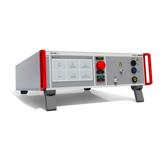
Page 40: Design And Functions
AMETEK CTS NSG 3040A, 3060A series Design and Functions 5.1. Front view NSG 3040A and NSG 3060A ACTIVE indication EUT test supply CRO Trigger output 5V Touch display Rotary wheel (Inc. / Dec /Enter) Start / Pause "Test On" 10 Stop HV pulse Burst output 50 ... - Page 41 AMETEK CTS NSG 3040A, 3060A series ACTIVE indication EUT test supply CRO Trigger output 5V Touch display Rotary wheel (Inc. / Dec /Enter) Start / Pause "Test On" 10 Stop HV pulse Burst output 50 11 Back Ground reference (calibration) BNC - CRO Trigger The generator trigger can be checked at the BNC output, e.g.
-
Page 42: Rear View
AMETEK CTS NSG 3040A, 3060A series 5.2. Rear view 1 EUT supply input 6 Fail, EUT 1 10 Ethernet interface 2 Surge output HV - COM 7 Sys Link IN 11 Opto Link Interface 3 Ventilator 8 USB A interface 12 Sys Link OUT 4 Mains Switch 9 USB B interface... - Page 43 AMETEK CTS NSG 3040A, 3060A series 1 EUT supply input 6 Fail, EUT 1 10 Ethernet interfaces 2 Surge output HV - COM 7 Sys Link IN 11 Opto Link Interface 3 Ventilator 8 USB A interface 12 Sys Link OUT 4 Mains Switch 9 USB B interface 13 Mains input device...
-
Page 44: Parameter Setting
AMETEK CTS NSG 3040A, 3060A series 5.3. Parameter setting All phenomena offer similar parameter setting procedures. The figure below explains the different actions for parameter setting. Parameter change All white colored parameters are changeable. Blue colored parameters are normally defined by the used standard and fixed. -
Page 45: Test Setting And Run Window
AMETEK CTS NSG 3040A, 3060A series 5.4. Test setting and Run Window Test setting window In the test window the user can enter the parameters of the test. Further it is possible to change in another test menu and to safe the test as Easy Link or User test. Test setting window The window shows all parameter settings for the test. -
Page 46: Set And Test Window
AMETEK CTS NSG 3040A, 3060A series 5.4.1. Set and test window The screen for each phenomenon separated in two different screens. The figure below illustrates the state machine during the testing. SET screen: Screen for setting all test parameters (yellow circle). TEST screen: Screen during a test is running. - Page 47 AMETEK CTS NSG 3040A, 3060A series 5.4.1.1. Run window menu The run Window Menu offers the following functions during Pause and when finished. The most functions are available in all phenomenon. Zoom view Enables / disables the zoom view Zoom parameter configuration Change display parameter Click the parameter you like to change.
-
Page 48: Menu
AMETEK CTS NSG 3040A, 3060A series Menu Home Returns to the Home screen EUT and supply configuration - EUT configuration (power line arrangement / data lines) - Test supply and coupling - Supply path and voltage - Limiter for EUT current and voltage Menu setting: Opens the menu for general settings Manager Test files management for test library configuration... -
Page 49: Menu For Settings
AMETEK CTS NSG 3040A, 3060A series 6.2. Menu for Settings Overview For any general setting, Press Menu and select one of the menus. Screen after touch on Manager The user configures in this menu the library Manager of all existed test files. Rename of tests Mark as visible or hide Remove test from the library... -
Page 50: Manager
AMETEK CTS NSG 3040A, 3060A series 6.3. Manager Manager The user configures in this menu the library Manager of all existed test files. - Rename of tests (Standards & User) - Mark as visible or hide (Standards & User) - Remove test from the library (User) 6.4. -
Page 51: Eut Setup
AMETEK CTS NSG 3040A, 3060A series 6.5. EUT Setup In the EUT setting the user specified his EUT. With this information the generator software will configure all settings to the EUT requirements. The user defines: Mode of supply voltage (AC/DC) Configuration of the EUT supply wiring Default channel for the power supply The mains supply voltage... -
Page 52: Eut Setup / Test
AMETEK CTS NSG 3040A, 3060A series 6.5.1. EUT Setup / TEST TEST Power configuration for the actual connected EUT Supply: For CDN with AC/DC coupling the coupling mode will automatically change between AC and DC. Coupling: Power lines & data lines Phase Filter: Select the used lines - 1-phase... - Page 53 AMETEK CTS NSG 3040A, 3060A series Path Vnom (controlled at PF2) Any voltage (example 230 V- 10%) The voltage of the XFMR is set to the following voltages: Power Fail: settled DIP voltage Power magnetic field: All other phenomenon’s: Vnom (PF2) NOTE: PF2 is used for operating a EUT with different voltage than the actual mains voltage.
-
Page 54: Setup
AMETEK CTS NSG 3040A, 3060A series 6.6. Setup The Setup menu is the place where the user configures his test equipment and device behavior. General: Setup menu for the NSG 3000A system Equipment’s: Setup menu for equipment’s connected to the NSG 3000A test generator Overview Setup General System:... -
Page 55: Setup / System Menu
AMETEK CTS NSG 3040A, 3060A series 6.6.1. Setup / System menu Language: Selection English (default), German, Espanol, Francais, Italian, Polish, Russia… Import / Export Settings: Export/ import the system settings to file syssettings.bkp FACTORY SETTING: Sets all parameters to the factory settings, even the messages. -
Page 56: Setup / Display
AMETEK CTS NSG 3040A, 3060A series 6.6.4. Setup / Display Brightness level: Move the cursor to change Timer: Dims the backlighting after the preset time if no touch is carried. Setting: 1, 2, 10, 20 minutes 1 hour never 6.6.5. Setup / Remote Individual setting for: - IP Address... -
Page 57: Setup / Application / Process & Sync
AMETEK CTS NSG 3040A, 3060A series 6.6.6. Setup / Application / Process & Sync HV – COM capacitance: HV – COM output at rear side direct or coupled with 18 µF Synchronization: Phase angle sync form EUT line or from an external sync signal. -
Page 58: Setup / Equipment / Devices & Modules
AMETEK CTS NSG 3040A, 3060A series 6.6.7. Setup / Equipment / Devices & Modules The Device & Modules screen shows all recognized modules in the present system. System equipment’s are displayed with his internal modules. A “long press” to NSG 3040A will show the serial number and software number and calibration info of the NSG 3040A generator. -
Page 59: Setup / Equipment / External Couplers
AMETEK CTS NSG 3040A, 3060A series 6.6.8. Setup / Equipment / External Couplers Define and load an external coupler CDN & Coil external CDN or automatic detection, when connected Coil Magnetic field coil CDN coupling / decoupling network: - CDN 117A C4-4-1 - CDN 117A C6-4-1 - CDN 118A C4-4-1 - CDN 118A C6-4-1... -
Page 60: Setup / Equipment / Transformers
AMETEK CTS NSG 3040A, 3060A series 6.6.9. Setup / Equipment / Transformers Define and load an external transformer Variable Motorized variac transformer Tapped Tapped transformer H-Field Magnetic field current transformer + ADD Default transformer Library that can selected by Variable Transformer: Var 3005A-S16A Tapped Transformer: TVT 1-250-16... -
Page 61: Variable Voltage Transformers Adjustment Procedure
AMETEK CTS NSG 3040A, 3060A series 6.7. Variable voltage transformers adjustment procedure The NSG 3000A can control an external voltage source with a 0-10 V analogue DC signal. The 10 V level corresponds to the max. output voltage of the connected VAR 3005A-S16. For the correct setting it is necessary to know the max. -
Page 62: Adjustment Procedure For Variable Transformers
AMETEK CTS NSG 3040A, 3060A series 6.7.1. Adjustment procedure for variable transformers For adjust a variable transformer, select first the device to adjust in: Menu / Setup / Transformers / Variable 1. Select CHANGE or make a Long click into the device for change into the software setup. - Page 63 AMETEK CTS NSG 3040A, 3060A series Check at Vnom (230 V) level. variable transformer output voltage - Settled nominal voltage: (230 V) 230 V/Max. voltage *10.00 V - Output (0-10 V) voltage: Read the value at the voltmeter and check if the value is inside the tolerance of ±...
- Page 64 AMETEK CTS NSG 3040A, 3060A series Final screen of max. voltage adjustment - Settled nominal voltage: (230 V) - Output (0-10 V) voltage: 230 V/Max. voltage *10.00 V 19. OK: Write the max. Voltage value into the parameter list and exit wizard. Previous: Jumpers to the previous page Cancel: Exit the wizard without change...
-
Page 65: Adjustment Procedure For Tapped Transformers With Analogue Dc Control Voltage
AMETEK CTS NSG 3040A, 3060A series 6.7.2. Adjustment procedure for tapped transformers with analogue DC control voltage For adjust a tapped transformer, select first the device to adjust in: Menu / Setup / Transformers / Variable The tapped transformer is programmed that the nominal voltage corresponds to 10.0V dc as 100% for set. -
Page 66: Test Equipment Nsg 3040A And Nsg 3060A Series
AMETEK CTS NSG 3040A, 3060A series Test Equipment NSG 3040A and NSG 3060A series The simulator NSG 3040A is separated in different main parts. The control unit is screened to all other parts. 7.1. NSG 3040A Control unit Power supply 1 App board controller 4 Power supply 2 Device board controllers... -
Page 67: Nsg 3060A
AMETEK CTS NSG 3040A, 3060A series 7.2. NSG 3060A Control unit Power supply 1 App board controller 4 Power supply 2 Device board controllers 5 Mains filter 3 HMI board, touch panel High voltage unit 6 High voltage power supply 13 Power Fail switch PF2 7a Energy storage capacitor, Surge 14 Power Fail switch PF1... -
Page 68: Technical Data
AMETEK CTS NSG 3040A, 3060A series Technical data 8.1. EFT Electrical Fast Transients Burst as per IEC 61000-4-4 Test Level NSG 3040A series NSG 3060A series 200 V – 4800 V ± 10% Step 1 V Open circuit voltage V* Technical data for Burst is identical 100 V –... -
Page 69: Surge Immunity Requirements As Per Iec 61000-4-5
AMETEK CTS NSG 3040A, 3060A series 8.2. SURGE Immunity requirements as per IEC 61000-4-5 8.2.1. Technical data surge module for NSG 3040A series Test Level NSG 3040A (16A) 200 V – 4800 V ± 10% Step 1 V Open circuit voltage V 100 A –... -
Page 70: Technical Data Surge Module For Nsg 3060A Series
AMETEK CTS NSG 3040A, 3060A series 8.2.2. Technical data surge module for NSG 3060A series Test Level NSG 3060A (16 A) 200 V – 6600 V ± 10% Step 1 V Open circuit voltage V 100 A – 3300 A ± 10% Short circuit current Wave shape open circuit 18 F line to line... -
Page 71: Pulsed Magnetic Field As Per Iec 61000-4-9
AMETEK CTS NSG 3040A, 3060A series 8.3. Pulsed magnetic Field as per IEC 61000-4-9 Test Level NSG 3040A series NSG 3060A series 200 V – 4800 V ± 10% Step 1 V 200 V – 6600 V ± 10% Step 1 V Generator charging voltage V approx. -
Page 72: Power Fail Generator For Dips, Interruption And Voltage Variation As Per Iec 61000-4-11
AMETEK CTS NSG 3040A, 3060A series 8.4. Power Fail Generator for DIPS, interruption and voltage variation as per IEC 61000-4-11 EUT supply Model NSG 3040A / NSG 3060A series Channel PF1 and PF2 AC voltage/current max. 300V/ 16 A Mains frequency 50/60 Hz DC voltage/current max. -
Page 73: Power Magnetic Field As Per Iec 61000-4-8
AMETEK CTS NSG 3040A, 3060A series 8.5. Power Magnetic Field as per IEC 61000-4-8 Parameter Value H-Field 1 to approx. 40 A/m using MFT 30 depend magnetic factor setting Frequency 50/ 60 Hz depend on mains frequency Coil factor settable Settings Transformer factor [V/A] 0.01 to 100 setting range... -
Page 74: Ring Wave Generator As Per Iec 61000-4-12
AMETEK CTS NSG 3040A, 3060A series 8.6. Ring wave Generator as per IEC 61000-4-12 The ring wave module is only for NSG 3060A series available. Test Level NSG 3060 series 200 V – 6600 V ± 10% Step 1 V Open circuit voltage V Voltage Wave shape (open circuit) -
Page 75: Telecom Surge Generator As Per Iec 61000-4-5 (T-Surge Module)
AMETEK CTS NSG 3040A, 3060A series 8.7. Telecom Surge Generator as per IEC 61000-4-5 (T-Surge module) The Telecom surge module is only for NSG 3060A series available. As per ITU and ETS recommendations NSG 3060A 200 V – 6’600 V 10 % Output voltage open circuit V Pulse 10/700s 10 s ... -
Page 76: Eut Supply Specifications
AMETEK CTS NSG 3040A, 3060A series 8.8. EUT Supply Specifications Standard models Model Remarks NSG 3040A series 300 VAC* / DC 16 A 1- phase NSG 3060A series 300 VAC* / DC 16 A 1- phase * AC 50/60 Hz EUT Fuse The NSG 3040A and NSG 3060S models have no internal fuse for the EUT supply. -
Page 77: Maintenance Setup And Service
When setting up the test national and international regulations regarding human safety must be guaranteed. It is recommended to connect the simulator to the ground reference plane of the test setup. The generators of the NSG 3000A series and their coupling networks, can be linked together to a fully automotive test setup. -
Page 78: Calibration And Verification
AMETEK CTS NSG 3040A, 3060A series 9.5. Calibration and verification 9.5.1. Factory calibration Every AMETEK CTS generator is entirely checked and calibrated as per international standard regulations before delivery. A calibration certificate is issued and delivered along with a list of the equipment used for the calibration proving the traceability of the measuring equipment. -
Page 79: Delivery Groups
AMETEK CTS NSG 3040A, 3060A series Delivery Groups 10.1. Basic equipment • Generator model: NSG 3000A model with recommended modules (Burst, Surge, Power Fail, Magnetic Field, Telecom Surge) • Mains cable • Mains cable for the EUT supply • Adapter for power cable •... - Page 80 AMETEK CTS NSG 3040A, 3060A series Surge Power Fail • TVT 1-250-16 tapped transformer - Transformer with taps at 40 % &, 70 %, 80 % - 230 V / 16 A • TVT 1-250-16.1 tapped transformer - Transformer with automatic controlled taps at 40 % &, 70 %, 80 % - 230 V / 16 A •...
-
Page 81: Eft Burst As Per Iec 61000-4-4
AMETEK CTS NSG 3040A, 3060A series EFT Burst as per IEC 61000-4-4 Burst Module 5/50 ns If the user reduces the test voltage in Quick Start, Standards, STEP or User Test, the storage capacitor will be discharged only by the burst pulses. The result is a higher test voltage on the EUT than indicated on the display until the storage capacitor is discharged to the preselected value. -
Page 82: Burst Menu Options From Test Setting
AMETEK CTS NSG 3040A, 3060A series 11.1.1. Burst Menu options from test setting The In every test mode, the user can select the following options. routines. Change to other test modes - Quick Start - STEPS - User Test - Standard Test Other: - Add to STEPS - Configuration... -
Page 83: Quick Start
AMETEK CTS NSG 3040A, 3060A series 11.1.2. Quick Start Easy and very fast operation of all standard functions of the equipment. The latest simulator settings are stored automatically and will be recalled when Quick Start is selected. Quick Start Menu Quick Start testing Devices: NSG 3040A Burst specification as per IEC 61000-4-4 Ed3 (2012) -
Page 84: Standard Test Routines
AMETEK CTS NSG 3040A, 3060A series 11.1.3. Standard test routines The user can select preprogrammed standard test routines. Change to Standard library Change to - Quick Start - STEPS - User Test Other: Add to STEPS Configuration Save as User Test Load Defaults Within this test routine all standard parameters can be changed online during testing. -
Page 85: User Test Routines
AMETEK CTS NSG 3040A, 3060A series 11.1.4. User Test Routines The user can program, save and recall his own specific user test routines, created by himself. The user test routines library offers various useful self-created tests for testing and development. Operating Manual V 1.04 85 / 157... -
Page 86: Step Routines
AMETEK CTS NSG 3040A, 3060A series 11.1.5. STEP Routines The user can store, his own specific test routines he need to repeat during his test session. After switch-off the generator all these routines are deleted. If more than one STEP routine is in the library, the Program will run one sequence after the other and will stop when the last STEP sequence has finished. -
Page 87: Burst Settings And Limits
AMETEK CTS NSG 3040A, 3060A series 11.2. Burst Settings and limits 11.2.1. Configuration In the configuration menu the user set the following parameters: - Signal trigger for start the test or step is indicated by the blinking Start button. - Trigger out signal at the BNC plug on generator front side - Behavior of the EUT Monitor 1, BNC plug at the rear side Iterations The voltage Iteration tests the parameters changes after each step/cycle as shown in the figure below. - Page 88 The test will immediately stop and is finished. - Pause The test breaks and can be continued with START/PAUSE EUT Monitor input signal EUT Monitor BNC plug on rear side of the NSG 3000A series generator Input Status of BNC input of EUT monitor 1...
-
Page 89: Max Burst Impulses / S
AMETEK CTS NSG 3040A, 3060A series 11.2.2. Max Burst impulses / s Burst spike limit of the electrical burst switch: The pulse switch is a highly reproducible semiconductor switch. Spike frequencies up to 1000 kHz are by a factor of 10 higher than recommended in the actual EFT standards. This means of course that also the pulse energy would be 10 times higher. -
Page 90: Burst Generation
AMETEK CTS NSG 3040A, 3060A series 11.3. Burst generation 11.4. Test voltage with Burst as per IEC 61000-4-4 Burst generators, which the specifications in accordance with IEC 61000-4-4 are limited at the maximum output voltage. The efficiency of the burst pulses decreases with the numbers of couplings. Therefore, the maximum test voltage is limited depending on the number of tested lines. -
Page 91: Coupling/Decoupling Network
AMETEK CTS NSG 3040A, 3060A series 11.5. Coupling/decoupling network The decoupling part of the coupling network must be: - filter the interference pulses in the direction to the power supply; - protect other systems that are connected to the same power supply and - realize a high impedance of the power supply, e.g. -
Page 92: Burst Test Setup
AMETEK CTS NSG 3040A, 3060A series 11.6. Burst Test Setup - The test generator and the coupling network should be connected to the reference ground plane (acc. to high frequency requirements). - The equipment under test must be isolated from the reference ground plane. The distance should be 10 cm. Being part of the EUT, these requirements are also recommended for all connected cables. -
Page 93: Test Setup With Capacitive Coupling Clamp
AMETEK CTS NSG 3040A, 3060A series 11.6.1. Test setup with capacitive coupling clamp When using the coupling clamp, the minimum distance between the coupling plates and all other conductive surfaces (including the generator), except the ground reference plane beneath the coupling clamp and beneath the EUT, shall be at least 0.5 m. -
Page 94: Surge Immunity As Per Iec 61000-4-5
AMETEK CTS NSG 3040A, 3060A series Surge Immunity as per IEC 61000-4-5 Surge Module 1.2/50s – 8/20s The internal coupling network is designed for mains frequency 50 Hz / 60 Hz. When L – N coupling is selected an additional current of approx. 1.5 A flows, caused by the 18 F coupling capacitor and the pulse forming network. -
Page 95: Quick Start
AMETEK CTS NSG 3040A, 3060A series 12.1.1. Quick Start Easy and very fast operation of all standard functions of the equipment. The latest simulator settings are stored automatically and will be recalled when Quick Start is selected. Quick Start Menu Quick Start testing 12.1.1.1. -
Page 96: Standard Test Routine
AMETEK CTS NSG 3040A, 3060A series 12.1.2. Standard test Routine The user can select preprogrammed standard test routines. Change to Standard library Change to - Quick Start - STEPS - User Test Other: - Add to STEPS - Configuration - Save as User Test - Load Defaults Within this test routine all standard parameters can be changed online during testing. - Page 97 AMETEK CTS NSG 3040A, 3060A series 12.1.2.2. Iteration of the standard test procedure as per IEC 61000-4-5 The surges must be applied synchronized to the voltage phase at the respective angle and the peak value of the AC. voltage wave (positive and negative).
-
Page 98: User Test Routines
AMETEK CTS NSG 3040A, 3060A series 12.1.3. User Test Routines The user can program, save and recall his own specific user test routines, created by himself. The extended menu offers various useful tests for testing and development. SAVE AS USER TEST Save the actual test as user test. The user defines the name of the test Operating Manual V 1.04 98 / 157... -
Page 99: Step Routines
AMETEK CTS NSG 3040A, 3060A series 12.1.4. STEP Routines The user can store, his own specific test routines he need to repeat during his test session. After switching off the generator all these routines are deleted. If more than one STEP routine is in the library, the Program will run one sequence after the other and will stop when the last STEP sequence has finished. - Page 100 AMETEK CTS NSG 3040A, 3060A series The ANSI coupling is only implemented in NSG 3060A models with built in surge module ANSI A coupling after n pulses The coupling mode with 12 Ω und 9 µF will automatically be changed after the preselected number of pulses has been released.
-
Page 101: Surge Pulse Settings
AMETEK CTS NSG 3040A, 3060A series 12.2. Surge pulse settings 12.2.1. Configuration In the configuration menu the user can set the following parameters: - Trigger out signal at the BNC plug on generator front side - Signal trigger for the impulse or event when Start button is blinking - Behavior of the EUT Monitor 1 on BNC plug on rear side 12.2.1.1. - Page 102 AMETEK CTS NSG 3040A, 3060A series 12.2.1.2. Signal Trigger The trigger out signal is a programmable 5V edge signal located at the front side BNC Trigger plug. This signal is for trigger other devices like oscilloscopes or other devices. The generator offers the following trigger out options: - At Start - Each Pulse every surge impulse (cycle) release...
-
Page 103: Hv-Com Capacitance (18 Μf Capacitor)
AMETEK CTS NSG 3040A, 3060A series 12.2.2. HV-COM capacitance (18 µF capacitor) The HV – COM output includes a configurable output capacity with 18 µF. Using AMETEK CTS coupling- decoupling networks, the coupling capacitor is part of the CDN. For other applications e.g., pulsed surge magnetic field or a surge verification requires an 18 µF capacitor in the circuit. -
Page 104: Surge Pulse Application
AMETEK CTS NSG 3040A, 3060A series 12.3. Surge pulse application 12.3.1. Phase synchronization in 3-phase system The synchronization in a 3-phase coupler system is taken from the phase L1 and Neutral. In case of a delta supply without neutral connected, an artificial neutral point is defined by a high impedance network. -
Page 105: Surge Pulse Application
AMETEK CTS NSG 3040A, 3060A series 12.4. Surge pulse application Discharge switch: The discharge switch is a highly reproducible semiconductor switch. 12.5. Coupling/decoupling network The coupling network must couple the interference pulses to the lines of a power supply system (AC or DC). Capacitive coupling is the specified coupling mode for surge testing. -
Page 106: Coupling To I / O Lines
AMETEK CTS NSG 3040A, 3060A series 12.5.2. Coupling to I / O lines The coupling to I/O lines is generally realized with other coupling networks than for power supply lines. The loading of the I/O lines with big coupling capacitors is mostly not possible. -
Page 107: Magnetic Field Test As Per Iec 61000-4-9
AMETEK CTS NSG 3040A, 3060A series Magnetic field test as per IEC 61000-4-9 Pulse magnetic fields are generated by lightning strokes on buildings and other metal structures including aerial masts, earth conductors and earth networks and by initial fault transients in low, medium and high voltage electrical systems. - Page 108 AMETEK CTS NSG 3040A, 3060A series For magnetic field testing the antenna correction factor shall be included. The operator can enter this factor within the setup menu under the service routine. Setup pulsed magnetic test field The following coils can be used ✓...
-
Page 109: Quick Start
AMETEK CTS NSG 3040A, 3060A series 13.1.1. Quick Start Easy and very fast operation of all standard functions of the equipment. The latest simulator settings are stored automatically and will be recalled when Quick Start is next selected. Quick Start Menu Quick Start testing for 100 A/m Operating Manual V 1.04... -
Page 110: Standard Test Routine
AMETEK CTS NSG 3040A, 3060A series 13.1.2. Standard test Routine The user can select preprogrammed standard test routines. Change to Standard library Change to - Quick Start - User Test Other: - Add to STEPS - Configuration - Save as User - Load Defaults Within this test routine all standard parameters can be changed online during testing. -
Page 111: User Test Routines
AMETEK CTS NSG 3040A, 3060A series 13.1.3. User Test Routines The user can program, save and recall his own specific user test routines, created by himself. The extended menu offers various useful tests for testing and development. SAVE AS USER TEST Save the actual test as user test. The user defines the name of the test Operating Manual V 1.04 111 / 157... -
Page 112: Voltage Dips And Interruptions & Voltage Variation As Per Iec 61000-4-11
AMETEK CTS NSG 3040A, 3060A series Voltage Dips and Interruptions & voltage variation as per IEC 61000-4-11 Main Menu Power Fail for voltage dips and interrupt tests and voltage variation 14.1. Test setup for DIPS and Interruption tests Voltage DIPS For voltage DIPS a connection must be made from the NSG 3000A PF2 input to the variable transformer PF2 or tapped transformer, where the reduced voltage is... - Page 113 AMETEK CTS NSG 3040A, 3060A series Setup for dU mode The generator is connected as follow: PF1: Mains voltage from the grid PF2: Reduced voltage preset for the dip test. Mostly set to 40%, 70% or 80% of the mains voltage The internal generator switch will change the EUT supply voltage between PF1 and reduced PF2 voltage.
-
Page 114: Operation
AMETEK CTS NSG 3040A, 3060A series 14.2. Operation Dips Module for voltage Dips and short interruptions. The menu offers different test routines for pulsed magnetic field testing. Click into Voltage / DIPS menu loads the last used menu. Of the following routines below. Quick Start Easy and fast online-operation of the equipment for voltage DIPS and power interruption tests. -
Page 115: Quick Start
AMETEK CTS NSG 3040A, 3060A series 14.2.1. Quick Start Easy and very fast operation of all standard functions of the equipment. The latest simulator settings are stored automatically and will be recalled when Quick Start is next selected. Explanations Phase angle Duration of a single event Repetition rate (time between two events) Mode Channel select (PF1, PF2 or V) -
Page 116: Standard Test Routines
AMETEK CTS NSG 3040A, 3060A series 14.2.2. Standard Test Routines 14.2.2.1. IEC 61000-4-11 (AC power supply mains) If the external transformer VAR 3005A-S16 is used, controlled by an analogue 0-10V control voltage, the test is conducted automatically. If this option is not available, the manual test routine shall be used. Using a manual tapped transformer TVT 1-250-16, the user must connect the PF2 input with the correct plug at the TVT 1-250-16. -
Page 117: User Test Routines
AMETEK CTS NSG 3040A, 3060A series 14.2.3. User Test Routines The user can program, save and recall his own specific user test routines, created by himself. The user test routines library offers various useful self-created tests for testing and development. The user can program, save and recall his own specific user test routines, created by himself. -
Page 118: Voltage Variation
AMETEK CTS NSG 3040A, 3060A series 14.3. Voltage Variation Main Menu Power Fail for voltage dips and interrupt tests and voltage variation The voltage variation menu requires a motorized variable transformer VAR 3005A-S16 Attention Operating Manual V 1.04 118 / 157... -
Page 119: The Power Fail Test
AMETEK CTS NSG 3040A, 3060A series 14.4. The Power Fail Test 14.4.1. Test routines termination The test routine for power fail starts with an event with the duration (td), followed by a repetition time (tr). For operating, the NSG generator has the following handling for the test routine Single Test routine Test routine in a test link implemented ... -
Page 120: Overcurrent
AMETEK CTS NSG 3040A, 3060A series 14.5. Overcurrent Power switches The power switches are electronically protected against overload and short- circuits. The nominal current of the switches is 25 A (16 A model). Special protection requirements of the EUT must be separately assured by the user. -
Page 121: Voltage Drop Over The Pfs Switch
AMETEK CTS NSG 3040A, 3060A series 14.6. Voltage drop over the PFS switch The voltage drop, over the internal PFS switch is shown in the diagram below. current [A] voltage drop [V] 0.01 1.18 1.62 2.43 2.60 2.75 2.82 2.90 2.97 3.05 3.12... -
Page 122: The Power Fail Test
AMETEK CTS NSG 3040A, 3060A series 14.7. The Power Fail Test The generator type NSG 3000A simulates the following interference: - Voltage dips - Voltage interruptions - Voltage variations - Inverse 14.7.1. Voltage Interruptions Depending on the preselected test parameters at the front panel of the simulator the power supply for the EUT is interrupted for a certain time and at a certain phase angle (AC power supplies). -
Page 123: Voltage Dips, Voltage Variations
AMETEK CTS NSG 3040A, 3060A series 14.7.2. Voltage dips, voltage variations Depending on the preselected test parameters, the test voltage is changed to a higher or to a lower value for a certain duration and at a certain phase angle. Voltage variations are normally related to the nominal value of the supply voltage. -
Page 124: The Power Fail Verification
AMETEK CTS NSG 3040A, 3060A series 14.8. The Power Fail Verification Program setting: During the test the power change to PF2 for 5 seconds. During these 5 seconds the user must connect the CA PFS to the output of the generator. A. -
Page 125: Test Setup And Accessories
AMETEK CTS NSG 3040A, 3060A series 14.9. Test setup and accessories 14.9.1. Transformer type TVT 1-250-16 The transformer shall be used to generate under-voltages in ac power supply systems. According to the IEC 61000- 4-11 and the EN 50081-2 voltage dips shall be generated as shown in fig. below. Different test levels are recommended 14.9.1.1. - Page 126 AMETEK CTS NSG 3040A, 3060A series 14.9.1.4. Technical Data TVT 1-250-16 models Design Tapped auto-transformer with 40%, 70%, 80%, 100 % output voltage Input: Voltage Uin: max. 250 V Frequency 50/60 Hz Tap selection manually (TVT 1-250-16) banana plugs for 40%, 70%, 80% Remote control 0 to 10V dc (TVT 1-250-16.1) for 40%, 70%, 80% Output:...
-
Page 127: Variable Transformer Variable Transformer Var 3005A-S16
AMETEK CTS NSG 3040A, 3060A series 14.9.2. Variable Transformer variable transformer VAR 3005A-S16 The motor variable transformer can be used to simulate power supply failures as under-voltages, voltage interruptions and voltage variations. The basic standard IEC 61000-4-11 and the generic standard EN 61000-6-2 are specifying these phenomena. - Page 128 AMETEK CTS NSG 3040A, 3060A series 14.9.2.3. Technical data variable transformer VAR 3005A-S16 Input: Voltage Vin: max. 250 V Frequency 50/60 Hz Output Vout: 0 – 260 V for channel PF2 Voltage variable Voltage fix Vout: Vin for channel PF1 Current max: 16 A Power...
-
Page 129: Power Frequency Magnetic Field As Per Iec 61000-4-8
AMETEK CTS NSG 3040A, 3060A series Power frequency Magnetic Field as per IEC 61000-4-8 15.1. Operation The Power magnetic menu offers different test routines for magnetic field testing. Click into Power Magnetic Field menu loads the last used menu. Of the following routines below. Quick Start Easy and fast online-operation with the phenomenon Surge. -
Page 130: Required Device Setting To Perform A Power Frequency Magnetic Field Test
AMETEK CTS NSG 3040A, 3060A series 15.1.2. Required device setting to perform a power frequency magnetic field test To perform a 50/60 Hz magnetic field test, the NSG generator must be configured with the used hardware in the menu: Menu / SETUP / Equipment 1. -
Page 131: Test Setup For Power Frequency Magnetic Field Test
AMETEK CTS NSG 3040A, 3060A series 15.1.3. Test setup for power frequency magnetic field test For magnetic field testing the power mains input at PF1 must be disconnected. Warning A message appears to confirm, that the PF1 generator input is disconnected from the mains. -
Page 132: Test Setup With Mft 100 For H-Fields Up To 1.000 A/M
AMETEK CTS NSG 3040A, 3060A series 15.1.5. Test setup with MFT 100 for H-Fields up to 1.000 A/m Schematics Test setup Schematics and Test setup with NSG 3040A, VAR 3005A-S16, MFT 100 and MFC 1000.1 Options required for magnetic field tests as per IEC 61000-4-8 - External variable motor variac VAR 3005A-S16 - External magnetic field antenna MFC 1000.x - External current transformer MFT 100 to test 100 A/m (continuous) and up to 1.000 A/m (short-term) -
Page 133: Telecom Surge Immunity As Per Iec 61000-4-5
AMETEK CTS NSG 3040A, 3060A series Telecom Surge Immunity as per IEC 61000-4-5 Surge Module 10/700s – 5/320s 16.1. Operation The surge menu offers different test routines for burst testing. Click into Telecom surge menu loads the last used menu. Of the following routines below. The surge menu offers different test routines for surge testing. -
Page 134: Generator Network For Telecom Surge
AMETEK CTS NSG 3040A, 3060A series 16.1.1. Generator Network for Telecom Surge The figure below shows the elements and schematic of the Telecom surge pulse circuit T1 to T4 Ports for direct application HV, COM Port to external coupling network All telecon output are served when using telecom surge application. -
Page 135: Quick Start
AMETEK CTS NSG 3040A, 3060A series 16.1.2. Quick Start Easy and very fast operation of all standard functions of the equipment. The latest simulator settings are stored automatically and will be recalled when Quick Start is next selected. Quick Start Menu Quick Start testing Coupling setting The generator HC - COM... -
Page 136: Standard Test Routine
AMETEK CTS NSG 3040A, 3060A series 16.1.3. Standard test Routine The user can select preprogrammed standard test routines. Change to Standard library Change to - Quick Start - STEPS - User Test Other: - Add to STEPS - Configuration - Save as User Test - Load Defaults With configuration the user can “CHANGE STANDARD TO INACTIVE”... -
Page 137: Step Test Routines
AMETEK CTS NSG 3040A, 3060A series 16.1.4. STEP Test Routines The user can store, his own specific test routines he need to repeat during his test session. After switching off the generator all these routines are deleted. If more than one STEP routine is in the library, the Program will run one sequence after the other and will stop when the last STEP sequence has finished. -
Page 138: Telecom Surge Pulse Settings
AMETEK CTS NSG 3040A, 3060A series 16.2. Telecom Surge pulse settings 16.2.1. Configuration In the configuration menu the user set the following parameters: - Signal Trigger out signal at the BNC plug on generator front side - Start trigger for the impulse or event when Start button is blinking - Behavior of the EUT Monitor 1 on BNC plug on rear side 16.2.1.1. -
Page 139: Operation
AMETEK CTS NSG 3040A, 3060A series Ring wave Immunity as per IEC 61000-4-12 Ring wave Module 0.5 s – 100 kHz The internal coupling network is designed for mains frequency 50 Hz / 60 Hz. Tests with 400 Hz mains frequency destroy the coupling network. An external coupling network is recommended with inductors and capacitors matched to the 400 Hz mains frequency. -
Page 140: Quick Start
AMETEK CTS NSG 3040A, 3060A series 17.1.1. Quick Start Easy and very fast operation of all standard functions of the equipment. The latest simulator settings are stored automatically and will be recalled when Quick Start is next selected. Quick Start Menu Quick Start testing While a test runs, the user can select parameters. -
Page 141: Standard Test Routine
AMETEK CTS NSG 3040A, 3060A series 17.1.2. Standard test Routine The user can select preprogrammed standard test routines. Change to Standard library Change to - Quick Start - STEPS - User Test Other: - Add to STEPS - Configuration - Save as User Test - Load Defaults Within this test routine all standard parameters can be changed online during testing. - Page 142 AMETEK CTS NSG 3040A, 3060A series Iteration of the standard test procedure as per IEC 61000-4-12 The ring wave must be applied synchronized to the voltage phase at the respective angle and the peak value of the a.c. voltage wave (positive and negative).
-
Page 143: User Test Routines
AMETEK CTS NSG 3040A, 3060A series 17.1.3. User Test Routines The user can program, save and recall his own specific test routines. The next pages show the selection of the functions. SAVE AS USER TEST Save the actual test as user test. The user defines the name of the test Operating Manual V 1.04 143 / 157... -
Page 144: Step Routines
AMETEK CTS NSG 3040A, 3060A series 17.1.4. STEP Routines The user can store, his own specific test routines he need to repeat during his test session. After switching off the generator all these routines are deleted. If more than one STEP routine is in the library, the Program will run one sequence after the other and will stop when the last STEP sequence has finished. -
Page 145: Ring Wave Pulse Settings
AMETEK CTS NSG 3040A, 3060A series 17.2. Ring wave pulse settings 17.2.1. Configuration In the configuration menu the user set the following parameters: - Signal Trigger at the BNC plug on generator front side - Signal trigger for the impulse or event when Start button is blinking - Behavior of the EUT Monitor 1 on BNC plug on rear side 17.2.1.1. - Page 146 AMETEK CTS NSG 3040A, 3060A series 17.2.1.2. Signal Trigger The Start Trigger occurs by pressing the blinking START / PAUSE button or with an external trigger positive slope signal at the rear side BNC Ext. Trigger plug. The start trigger offers the following status: - Automatic - At Start (starts after the trigger) - Each pulse (same as trigger out)
-
Page 147: Ring Wave Pulse Application
AMETEK CTS NSG 3040A, 3060A series 17.3. Ring wave pulse application 17.3.1. Phase synchronization in 3-phase system The synchronization in a 3-phase coupler system is taken from the phase L1 and neutral. In case of a delta supply without neutral connected, an artificial neutral point is defined by a high impedance network. -
Page 148: Ring Wave Pulse Application
AMETEK CTS NSG 3040A, 3060A series 17.4. Ring wave pulse application Discharge switch: The discharge switch is a highly reproducible semiconductor switch. 17.5. Coupling/decoupling network The coupling network must couple the interference pulses to the lines of a power supply system (AC or DC). Capacitive coupling is the specified coupling mode for surge testing. -
Page 149: Coupling To I / O Lines
AMETEK CTS NSG 3040A, 3060A series 17.5.2. Coupling to I / O lines The coupling to I/O lines is generally realized with other coupling networks than for power supply lines. The loading of the I/O lines with high coupling capacitors is mostly not possible. -
Page 150: Test Setup
AMETEK CTS NSG 3040A, 3060A series 17.6. Test setup According to the specifications of IEC 61000-4-12, the Ring wave generator has a source impedance of Generator impedance 12 Ω for a.c./d.c. power ports and shielded interconnection lines 30 Ω for interconnection lines. 50 Ω... -
Page 151: Appendix
AMETEK CTS NSG 3040A, 3060A series Appendix 18.1. Declaration of CE-Conformity 18.1.1. CE-Conformity NSG 3040A series declares, that under is sole responsibility, the product’s listed below, including all their options, are conformity with the applicable CE directives listed below using the relevant section of the following EC standards and other normative documents. -
Page 152: Ce-Conformity Nsg 3060A Series
AMETEK CTS NSG 3040A, 3060A series 18.1.2. CE-Conformity NSG 3060A series Manufacturer: AMETEK CTS GmbH Address: Sternenhofstr. 15 CH 4153 Reinach BL1 Switzerland declares, that under is sole responsibility, the product’s listed below, including all their options, are conformity with the applicable CE directives listed below using the relevant section of the following EC standards and other normative documents. -
Page 153: Ce-Conformity Tapped Voltage Transformer Tvt 1-250-16
AMETEK CTS NSG 3040A, 3060A series 18.1.3. CE-Conformity Tapped Voltage Transformer TVT 1-250-16 Manufacturer: AMETEK CTS GmbH Address: Sternenhofstr. 15 CH 4153 Reinach BL1 Switzerland declares, that under is sole responsibility, the product’s listed below, including all their options, are conformity with the applicable CE directives listed below using the relevant section of the following EC standards and other normative documents. -
Page 154: Ce-Conformity Tapped Voltage Transformer Tvt 1-250-16.1
AMETEK CTS NSG 3040A, 3060A series 18.1.4. CE-Conformity Tapped Voltage Transformer TVT 1-250-16.1 Manufacturer: AMETEK CTS GmbH Address: Sternenhofstr. 15 CH 4153 Reinach BL1 Switzerland declares, that under is sole responsibility, the product’s listed below, including all their options, are conformity with the applicable CE directives listed below using the relevant section of the following EC standards and other normative documents. -
Page 155: Ce-Conformity Cci (Capacitive Coupling Clamp)
AMETEK CTS NSG 3040A, 3060A series 18.1.5. CE-Conformity CCI (capacitive coupling clamp) Manufacturer: AMETEK CTS GmbH Address: Sternenhofstr. 15 CH 4153 Reinach BL1 Switzerland declares, that under is sole responsibility, the product’s listed below, including all their options, are conformity with the applicable CE directives listed below using the relevant section of the following EC standards and other normative documents. -
Page 156: Nsg 3040A Series General Block Diagram
AMETEK CTS NSG 3040A, 3060A series 18.2. NSG 3040A series General Block Diagram Operating Manual V 1.04 156 / 157... -
Page 157: Nsg 3060A Series General Diagram
AMETEK CTS NSG 3040A, 3060A series 18.3. NSG 3060A series General Diagram Operating Manual V 1.01 157 / 157...
Need help?
Do you have a question about the NSG 3000A Series and is the answer not in the manual?
Questions and answers