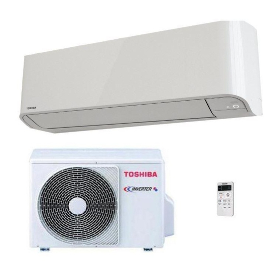
Summarization of Contents
2. SPECIFICATIONS
2-1. Unit Specifications
Detailed technical specifications for indoor and outdoor units, including capacity, power, and dimensions.
2-2. Operation Characteristic Curves
Graphical representation of unit performance under various operating conditions.
2-3. Capacity Variation by Temperature
How cooling and heating capacity changes with outdoor temperature.
3. REFRIGERANT R410A
3-1. Safety During Installation/Servicing
Precautions for safe installation and servicing when using R410A refrigerant.
3-2. Refrigerant Piping Installation
Guidelines for installing refrigerant piping, including material selection and processing.
3-3. Tools for R410A
List of specialized tools required for R410A systems and their interchangeability.
3-4. Recharging of Refrigerant
Step-by-step procedure for recharging the air conditioner with refrigerant.
3-5. Brazing of Pipes
Procedures and materials for brazing refrigerant pipes, including flux and methods.
4. CONSTRUCTION VIEWS
4-1. Indoor Unit Construction
Exploded view and dimensional details of the indoor unit components.
4-2. Outdoor Unit Construction
Exploded view and dimensional details of the outdoor unit components.
6. SPECIFICATIONS OF ELECTRICAL PARTS
6-1. Indoor Unit Electrical Parts
List of electrical components used in the indoor unit with their specifications.
6-2. Outdoor Unit Electrical Parts
List of electrical components used in the outdoor unit with their specifications.
7. REFRIGERANT CYCLE DIAGRAM
7-1. Refrigerant Cycle Diagram
Diagram illustrating the flow of refrigerant through the air conditioning system.
7-2. Operation Data
Operational data, including pressures and temperatures, under different cooling and heating conditions.
8. CONTROL BLOCK DIAGRAM
8-1. Indoor Unit Control Block Diagram
Functional block diagram for the indoor unit's control system and remote control.
8-2. Outdoor Unit Control Block Diagram
Functional block diagram for the outdoor unit's control system and inverter assembly.
9. OPERATION DESCRIPTION
9-1. Outline of Air Conditioner Control
Overview of how the air conditioner system is controlled by indoor and outdoor units.
9-3. Auto Restart Function
How to set, cancel, and manage the auto restart function after a power failure.
9-4. Remote Controller and Its Functions
Details on remote controller parts, operation, and display indications.
10. INSTALLATION PROCEDURE
10-1. Installation Diagram of Indoor and Outdoor Units
Visual guide showing the placement and dimensions for installing indoor and outdoor units.
10-2. Installation Parts and Tools
Lists optional installation parts and discusses fixing bolt arrangements for outdoor units.
10-3. Indoor Unit Installation
Procedures for selecting the installation place and mounting the indoor unit.
10-4. Outdoor Unit Installation
Guidelines for selecting installation location and precautions for outdoor unit installation.
10-5. Electrical Works
Instructions for connecting the power supply and wiring for both indoor and outdoor units.
10-6. Other Installation Procedures
Covers gas leak testing, remote control A-B selection, test operation, and auto restart setup.
11. HOW TO DIAGNOSE THE TROUBLE
11-1. First Confirmation
Initial checks for power supply, voltage, and program operations to confirm basic functionality.
11-2. Primary Judgment
Methods for initial fault diagnosis, including LED flashing and remote controller self-diagnosis.
11-3. Judgment by Flashing LED of Indoor Unit
Interpreting error codes displayed by indoor unit flashing LEDs for self-diagnosis.
11-4. Self-Diagnosis by Remote Controller
Using the remote controller in service mode to retrieve and interpret check codes for fault diagnosis.
11-5. Judgment of Trouble by Every Symptom
Troubleshooting guide based on specific symptoms like no power or unit stops.
11-6. How to Check Simple the Main Parts
Procedures for checking key components like pulse motor valves and temperature sensors.
11-7. How to Diagnose Trouble in Outdoor Unit
Diagnosing issues within the outdoor unit's inverter assembly and related components.
11-8. How to Check Simply the Main Parts
Procedures for checking PC boards, sensors, and electrical parts for faults.
11-9. Outdoor Fan Motor Diagnosis
Step-by-step guide to test the outdoor fan motor's functionality and identify potential errors.
11-10. Operation Cancel and Self-Cleaning
Instructions on how to cancel the CLEAN operation and manage the self-cleaning function.
12. HOW TO REPLACE THE MAIN PARTS
12-1. Indoor Unit Parts Replacement
Procedures for removing and replacing main parts of the indoor unit, like air filters and front panel.
12-2. Outdoor Unit Parts Replacement
Procedures for removing and replacing main parts of the outdoor unit, including cabinets and covers.
13. EXPLODED VIEWS AND PARTS LIST
13-1. Indoor Unit Exploded View and Parts List
Visual breakdown of the indoor unit with a corresponding list of all parts and their numbers.
13-2. Indoor Unit (Part-E) Parts List
List of specific parts for the indoor unit's electronic components (Part-E).
13-3. Outdoor Unit RAS-10BAV-E1 Parts List
List of parts for the RAS-10BAV-E1 outdoor unit with location and part numbers.
13-4. Outdoor Unit RAS-13BAV-E1 Parts List
List of parts for the RAS-13BAV-E1 outdoor unit with location and part numbers.
13-5. Outdoor Unit (Part-E) Parts List
List of specific electronic and sensor parts for the outdoor unit.


Need help?
Do you have a question about the RAS-13BKV-E1 and is the answer not in the manual?
Questions and answers