Table of Contents
Advertisement
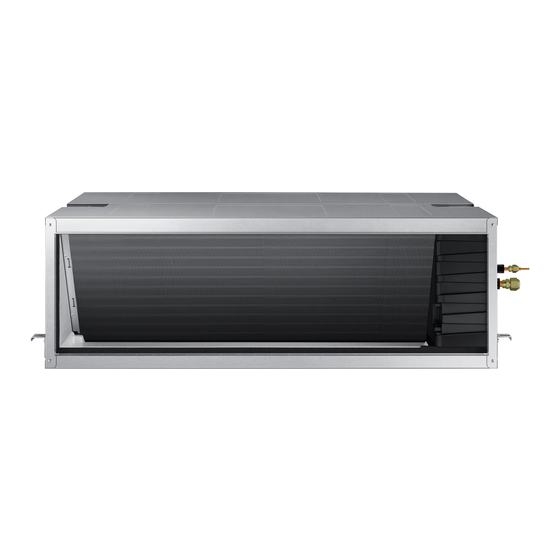
AIR CONDITIONER
AC200KNHPKH
AC250KNHPKH
AC200KXAPNH
AC250KXAPNH
SYSTEM AIR CONDITIONER
ndoor Unit
Outdoor Unit
I
Model Name :
AC200KNHPKH
AC200KXAPNH
AC250KNHPKH
AC250KXAPNH
Model Code :
AC200KNHPKH/EU
AC200KXAPNH/EU
AC250KNHPKH/EU
AC250KXAPNH/EU
CONTENTS
1. Precautions
2. Product Specifications
3. Disassembly and Reassembly
4. Troubleshooting
5. PCB Diagram
6. Wiring Diagram
7. Reference Sheet
Advertisement
Table of Contents
Troubleshooting

Related Manuals for Samsung AC200KXAPNH


Summarization of Contents
Precautions
1-1 Precautions for the Service
Guidelines for replacing electric parts, ensuring correct parts, and secure connections.
1-2 Precautions for the Static Electricity and PL
Warnings regarding static electricity sensitivity of PCB and safe distances from other electronics.
1-3 Precautions for the Safety
Safety measures for electrical hazards like shock or fire, including handling power cords and grounding.
1-4 Others
Guidelines for handling, storage, and specific procedures like pump down to prevent damage.
Product Specifications
2-1 The Feature of Product
Highlights key features of the air conditioner, including design, performance, and eco-friendliness.
2-2 Product Specifications
Detailed technical specifications for indoor and outdoor units, including dimensions, power, and noise levels.
2-3 Accessory
List of included accessories with their respective part codes and descriptions.
Disassembly and Reassembly
Necessary Tools
List of essential tools required for disassembly and reassembly procedures.
3-1 Indoor Unit
Step-by-step instructions for disassembling the indoor unit components.
3-2 Outdoor Unit
Step-by-step instructions for disassembling the outdoor unit components.
Troubleshooting
4-1 Wired remote controller
Troubleshooting errors displayed on the wired remote controller.
LED Display on the receiver & display unit
Interpreting LED indicator patterns for abnormal conditions on the receiver unit.
4-2 Outdoor Trouble shooting
Troubleshooting procedures and error codes specific to the outdoor unit.
4-3 Troubleshooting by symptoms
Guides for diagnosing and resolving issues based on observed symptoms.
4-3-1 Indoor temperature sensor (open/short)
Diagnosing and resolving indoor temperature sensor errors (open/short circuits).
4-3-2 Eva in and out sensor (open/short)
Diagnosing and resolving EVA IN/OUT sensor errors (open/short circuits).
4-3-3 Float switch(Open)
Troubleshooting procedures for float switch open circuit errors.
4-3-4 Fan error
Diagnosing and resolving errors related to the fan motor operation.
4-3-5 EEPROM error
Troubleshooting steps for EEPROM errors, often related to option settings.
4-3-6 Option error
Guidance for resolving errors related to incorrect indoor unit option settings.
4-3-7 Terminal Block's Terminal Fuse(Open)
Troubleshooting terminal block fuse open errors.
4-3-8 Communication error after finishing tracking (E202)
Resolving communication errors after tracking is completed.
4-3-9 Outdoor's service valve(Clog)
Troubleshooting clogged outdoor service valve issues.
4-3-10 No Power(completely dead) - Initial diagnosis
Initial diagnosis steps for units that show no power.
Outdoor unit is not powered on – Initial diagnosis ( 3phase)
Initial diagnosis for 3-phase outdoor units that do not power on.
4-3-11 E102 : Communication error between indoor and outdoor unit
Troubleshooting communication errors between indoor and outdoor units.
4-3-12 External Sensor Error (Error Code: E221, E231, E251, E320)
Diagnosing external sensor errors with specific error codes.
4-3-13 E403 : Freezing control causes comp. down
Troubleshooting compressor down due to freezing control.
4-3-14 E416 : Dischage temperature sensor error
Diagnosing discharge temperature sensor errors in the outdoor unit.
4-3-15 E440, E441 : Abnormal outside temperature halts operation of the compressor
Troubleshooting compressor halt due to abnormal outside temperatures.
4-3-16 Outdoor unit BLDC Fan1 or Fan2 error (E458 : Fan1 error, E475 : Fan2 error)
Diagnosing errors for outdoor unit BLDC Fan1 or Fan2.
4-3-17 E461: Compressor start error E467: Compressor wire missing error
Troubleshooting compressor start and wire missing errors.
4-3-18 E462 : Current protection control causes comp. down E484 : PFC overload error
Troubleshooting current protection and PFC overload errors.
4-3-19 E463 : OLP protection control caused comp. down
Troubleshooting compressor down due to OLP protection control.
4-3-20 E464 : O.C. (Over Current) error
Diagnosing and resolving Over Current (O.C.) errors.
4-3-21 E466: DC Link Over voltage/ Low voltage error
Troubleshooting DC Link over/low voltage errors.
4-3-22 Pipe Blocking Error (Error Code: E422)
Diagnosing and resolving pipe blocking errors.
4-3-23 The others
Troubleshooting for various other less common error codes and issues.
4-4 Setting Option Setup Method
Guide to setting indoor unit option codes using the wired remote controller.
4-5 Items to be checked first
Essential checks to perform before diagnosing unit malfunctions.
Setting an indoor unit address and installation option
Setting an indoor unit address
Procedure for setting the indoor unit's address via the remote controller.
Setting an indoor unit installation option
Procedure for setting the indoor unit's installation options via the remote controller.
Adjusting air flow
Automatic Air-Volume
Adjusting indoor unit fan speed based on installation conditions for optimal airflow.
Easy Tuning
Simple method to adjust airflow rate for cooling, heating, or silent operation.
PCB Diagram and Parts list
5-1 INDOOR UNIT
Diagrams and part list for the indoor unit's main printed circuit board.
EMI PBA
Diagram and part list for the EMI Printed Board Assembly.
BLDC PBA
Diagram and part list for the BLDC Printed Board Assembly.
5-2 OUTDOOR UNIT
Diagrams and part list for the outdoor unit's printed circuit boards.
5-2-1MAIN (cont.)
Details of the outdoor unit's main PCB, including connectors and parts.
5-2-2 Inverter
Diagram and part list for the inverter PCB.
ASS'Y PCB SUB-DRIVER (cont.)
Diagram and part list for the PCB sub-driver assembly.
5-2-3 EMI
Diagram and part list for the outdoor unit's EMI Printed Board Assembly.
5-2-4 Fan
Diagram and part list for the fan control PCB.
5-2-5 Communication
Diagram and part list for the communication module.
Wiring Diagram
6-1 Indoor Unit
Wiring diagram illustrating connections for the indoor unit.
6-2 Outdoor Unit
Wiring diagram illustrating connections for the outdoor unit.
Reference Sheet
7-1 Refrigerating Cycle Diagram
Visual representation of the refrigerant flow through the system.
7-2 Index of Model Name
Guide to understanding and decoding model names.
Need help?
Do you have a question about the AC200KXAPNH and is the answer not in the manual?
Questions and answers